
Related Manuals for Cornelius PRISM


Summary of Contents for Cornelius PRISM
- Page 1 PRISM Owner’s Manual Release Date: Publication Number: 548000096 Revision Date: November 5, 2018 Revision: C Visit the Cornelius web site at www.cornelius.com for all your Literature needs.
- Page 2 Commercial Warranty. Cornelius will not be responsible for any repair, replacement or other service required by or loss or damage resulting from any of the following occurrences, including but not limited to, (1) other than normal and proper use and normal...
-
Page 3: Table Of Contents
How to Check Prism Ratio ........ - Page 4 Prism Owner’s Manual Publication Number: 548000096 © 2018, Cornelius Inc.
-
Page 5: Safety Instructions
Prism Owner’s Manual SAFETY INSTRUCTIONS ALL S EAD AND OLLOW AFETY NSTRUCTIONS Safety Overview • Read and follow ALL SAFETY INSTRUCTIONS in this manual and any warning/caution labels on the unit (decals, labels or laminated cards). • Read and understand ALL applicable OSHA (Occupational Safety and Health Administration) safety regulations before operating this unit. -
Page 6: Qualified Service Personnel
Prism Owner’s Manual UALIFIED ERVICE ERSONNEL WARNING: Only authorized service personnel shall service the valve. ALL WIRING AND PLUMBING MUST CONFORM TO NATIONAL AND LOCAL CODES. FAILURE TO COMPLY COULD RESULT IN SERIOUS INJURY, DEATH OR EQUIPMENT DAMAGE. AFETY RECAUTIONS This unit has been specifically designed to provide protection against personal injury. -
Page 7: Operation
REAR VIEW Figure 1. The Cornelius Prism is capable of dispensing 3 CARBONATED BRANDS / SYRUP OR 3 NON CARBONATED BRANDS / SYRUP and comes with 3 variants as below, refer Table 1 on page 4. NOTE: Both carbonated and non carbonated beverages CANNOT BE DISPENCED IN THE SAME... -
Page 8: Cleaning Instruction
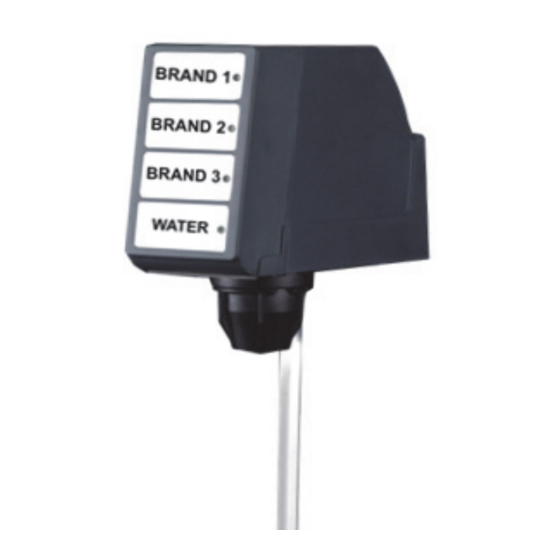
Table 1 Part No. Description Sanitary Lever Valves 620069302 Prism, Ceramic regulator, with mounting block and covers 620070464 Prism, Ceramic regulator, with covers Push Button Valves 620069304 Prism, Ceramic regulator, with mounting block and covers 620070465 Prism, Ceramic regulator, with covers... - Page 9 Prism Owner’s Manual Touch UI: 1x4 Key 1 - Brand 1 Key 2 - Brand 2 Key 3 - Brand 3 Key 4 - Water Figure 3. USH TO ANITARY EVER PTIFILL ATIO Bottom Figure 4. NOTE: The switch is located in the upper right hand corner of the back of the valve faceplate.
-
Page 10: How To Check Prism Ratio
Prism Owner’s Manual HECK RISM ATIO CAUTION: Do not expose the capacitive touch module wire to water. Table 2. 1. Remove the capacitive touch module by lifting it upward and Rear Cover Wires from valve body pulling out. Remove the rear to Capacitive touch modules valve cover. - Page 11 Prism Owner’s Manual Back Block 5. Press a brand to activate the time dispense into the proper syrup chamber. If the syrup level doesn’t fall within one bandwidth from the noted water level, turn Syrup 1 Syrup 3 the adjust screw on the appropri-...
-
Page 12: Knock Out Kit
ED300B and ED300BZ Ambient Carbonation Models: ED150BC, ED150BCZ, ED175BC, ED175BCZ, ED200BC, ED200BCZ, ED250BC, ED250BCZ, ED300BC and ED300BCZ NOTE: All IDC Units (Serial #: 62C0912JD002) since 2009 have panels that will accept the Prism Valve. Front Die Punch tool P/N 620070512 Rear Die Figure 10. - Page 13 Prism Owner’s Manual Knockout adapter plate P/N 620069489 Punch Tool Front Die Pan Head Phillips 8-32 Screws - 2 Qty Rear Die 3/18-16 Hex Head Bolt Knockout kit P/N-629097803 Figure 11. 629097803 – KNOCKOUT KIT BOM 629097803 – KNOCKOUT KIT: SERVICE PARTS...
-
Page 14: Knock Out Punch Instructions
Prism Owner’s Manual NOCK UNCH NSTRUCTIONS WARNING: Must wear required PPE and right tools before using the punch out tool. WARNING: Disconnect power to the unit before servicing following all lock out/tag out procedures established by the user. Verify all of the power is off to the unit before any work is performed. - Page 15 Prism Owner’s Manual Valve Mounting Panel 4. Align the 2 dowel pins of the “Rear Die” with Corresponding holes on the “Valve mounting panel”. Rear Die Figure 15. 5. Assemble “Front Die” loaded with “Punch Tool” to “Rear Die”, using 2 Phillip “8-32”...
-
Page 16: Installation Instructions
Prism Owner’s Manual INSTALLATION INSTRUCTIONS - P/N 620069489 NOCK DAPTER LATE Sheet Metal adapter plate for mounting prism valve Figure 19. NOCK DAPTER LATE UBING Table 4 1. Align knock out adapter plate with 4 holes of valve mounting panel from “Front Side”. -
Page 17: Installation Kit
Prism Owner’s Manual P/N 629097802 NSTALLATION 2. Prepare the tubing assemblies. Mounting screw P/N 620700602 90° Long Fittings P/N 620709073 Oetiker Clamp P/N 311908000 90° Short Fittings P/N 620709068 Flex Tube (Qty-2: 8ft Length) 620717791 Figure 21. NOTE: Check the O-rings on the 90° fittings for damage and replace if necessary. -
Page 18: Back Block Installation
Prism Owner’s Manual LOCK NSTALLATION Back Block Back Block Assembly Lock Pin Figure 22. Table 6. Route the Wire Figure 23. 1. Route the wire & connector through relief hole of rear adapter plate and back block. Figure 24. Publication Number: 548000096 - 14 - ©... - Page 19 Prism Owner’s Manual 2. Assemble all the lines with L - fittings on to the knock out adapter plate and Figure 25. 3. Align the back block inlet ports to the L- fittings and fasten back block to the valve panel using screws removed earlier (Use either existing screws or screws provided in the kit).
-
Page 20: Valve Installation
Prism Owner’s Manual ALVE NSTALLATION Table 7 Wires from valve body to Capacitive touch modules Rear Cover Valve Body 1. Slide, open the capacitive touch module. 2. Disconnect the wires from the capacitive touch mod- ule. 3. Remove the rear cover Capacitive Touch module Figure 27. - Page 21 Prism Owner’s Manual 5. Gently push the valve body against back block, until rear surface of the valve body is flush with the back block. Figure 29. 6. Lock the valve body and back block together with lock pin. Refer to Table 8 on page 18.
-
Page 22: Locking Valve With Back Block Using Lock Pin
Prism Owner’s Manual OCKING ALVE WITH LOCK SING Table 8. 1. Align the valve body with back block. Figure 31. 2. Insert the lock pin through the back block and valve body. Figure 32. Publication Number: 548000096 - 18 -... -
Page 23: Connection Diagram
Prism Owner’s Manual Closed Condition 3. Rotate both the spindles in the direc- tion shown to secure the lock pin in position and also to open the flow path of the drink. Open Condition Figure 33. ONNECTION IAGRAM DIP SWITCH... -
Page 24: Syrup And Water Maps
Prism Owner’s Manual YRUP AND ATER NOTE: For switch positions, refer figure 4 on page 5. SYRUP 1 SYRUP 3 PLAIN / CARBONATED SYRUP 2 WATER FRONT VIEW FRONT COVER FRONT VIEW REAR VIEW Figure 35. Publication Number: 548000096 - 20 -... -
Page 25: Touch Module And Cover Installation
Prism Owner’s Manual OUCH ODULE AND OVER NSTALLATION 1. Assemble rear cover. Figure 36. 2. Route the wires from valve body and con- nect with capacitive touch module, refer Figure 37. Capacitive Touch Module Figure 37. 3. Slide the touch module on the rear cover from top. -
Page 26: Schematics
Prism Owner’s Manual SCHEMATICS LUMBING IAGRAM Figure 40. Publication Number: 548000096 - 22 - © 2018, Cornelius Inc. -
Page 27: Wiring Diagram
Prism Owner’s Manual IRING IAGRAM Figure 41. © 2018, Cornelius Inc. - 23 - Publication Number: 548000096... -
Page 28: Illustrated Parts List
Prism Owner’s Manual ILLUSTRATED PARTS LIST ALVE SSEMBLY Figure 42 Publication Number: 548000096 - 24 - © 2018, Cornelius Inc. - Page 29 Prism Owner’s Manual Item No. Part No. Description Item No. Part No. Description 620069584 Micro Switch 620069122 Valve Body Assy. 183184000 O-ring 1.17 ID 103 CS 620069122A Valve Body 620069283 Diffuser Assy 620069122B Valve Body Plug 311086000 O-Ring.929 ID 070 CS...
-
Page 30: Prism Decal
Prism Owner’s Manual RISM ECAL Table 9 Part number Description 620070508 Coke Decal 620070509 Pepsi Decal 620070510 Generic Decal Decal dimensions: Per brand MATERIAL:-.010 CLEAR POLYCARBONATE WITH WHITE DIFFUSER Figure 43 Publication Number: 548000096 - 26 - © 2018, Cornelius Inc. - Page 32 Cornelius Inc. www.cornelius.com...
Need help?
Do you have a question about the PRISM and is the answer not in the manual?
Questions and answers