
Related Manuals for WAGO 750-439


Summary of Contents for WAGO 750-439
- Page 1 Manual WAGO-I/O-SYSTEM 750 750-439 8DI NAMUR Ex i 8-Channel Digital Input Module NAMUR, Ex i, Proximity Sensor acc. to EN 60947-5-6 Version 1.3.0, valid from HW Version 03, SW Version 03...
- Page 2 We wish to point out that the software and hardware terms as well as the trademarks of companies used and/or mentioned in the present manual are generally protected by trademark or patent. WAGO is a registered trademark of WAGO Verwaltungsgesellschaft mbH. Manual Version 1.3.0, valid from HW Version 03, SW Version 03...
-
Page 3: Table Of Contents
WAGO-I/O-SYSTEM 750 Table of Contents 750-439 8DI NAMUR Ex i Table of Contents Notes about this Documentation .............. 5 Validity of this Documentation ..............5 Revision History ..................5 Copyright....................6 Symbols ....................7 Number Notation ..................9 Font Conventions ..................9 Important Notes .................. - Page 4 Table of Contents WAGO-I/O-SYSTEM 750 750-439 8DI NAMUR Ex i Power Supply Concept ................39 6.2.1 Power Supply Concept for Marine Applications in Ex i ..... 41 Connection Example ................44 Commissioning ..................45 WAGO-I/O-CHECK ................45 e!COCKPIT .................... 46 Diagnostics ....................
-
Page 5: Notes About This Documentation
This documentation is only applicable to the I/O module 750-439 (8DI NAMUR Ex i). The I/O module 750-439 shall only be installed and operated according to the instructions in this manual and in the manual for the used fieldbus coupler or controller. -
Page 6: Copyright
Manual by third parties that violate pertinent copyright provisions is prohibited. Reproduction, translation, electronic and phototechnical filing/archiving (e.g., photocopying) as well as any amendments require the written consent of WAGO Kontakttechnik GmbH & Co. KG, Minden, Germany. Non-observance will involve the right to assert damage claims. Manual... -
Page 7: Symbols
WAGO-I/O-SYSTEM 750 Notes about this Documentation 750-439 8DI NAMUR Ex i Symbols Personal Injury! Indicates a high-risk, imminently hazardous situation which, if not avoided, will result in death or serious injury. Personal Injury Caused by Electric Current! Indicates a high-risk, imminently hazardous situation which, if not avoided, will result in death or serious injury. - Page 8 Notes about this Documentation WAGO-I/O-SYSTEM 750 750-439 8DI NAMUR Ex i Additional Information: Refers to additional information which is not an integral part of this documentation (e.g., the Internet). Manual Version 1.3.0, valid from HW Version 03, SW Version 03...
-
Page 9: Number Notation
WAGO-I/O-SYSTEM 750 Notes about this Documentation 750-439 8DI NAMUR Ex i Number Notation Table 2: Number Notation Number Code Example Note Decimal Normal notation Hexadecimal 0x64 C notation Binary '100' In quotation marks, nibble separated '0110.0100' with dots (.) Font Conventions... -
Page 10: Important Notes
2.1.1 Subject to Changes WAGO Kontakttechnik GmbH & Co. KG reserves the right to provide for any alterations or modifications. WAGO Kontakttechnik GmbH & Co. KG owns all rights arising from the granting of patents or from the legal protection of utility patents. -
Page 11: Technical Condition Of Specified Devices
These modules contain no parts that can be serviced or repaired by the user. The following actions will result in the exclusion of liability on the part of WAGO Kontakttechnik GmbH & Co. KG: •... -
Page 12: 2.1.4.1.2 Packaging
Important Notes WAGO-I/O-SYSTEM 750 750-439 8DI NAMUR Ex i Environmentally friendly disposal benefits health and protects the environment from harmful substances in electrical and electronic equipment. • Observe national and local regulations for the disposal of electrical and electronic equipment. -
Page 13: Safety Advice (Precautions)
WAGO-I/O-SYSTEM 750 Important Notes 750-439 8DI NAMUR Ex i Safety Advice (Precautions) For installing and operating purposes of the relevant device to your system the following safety precautions shall be observed: Do not work on devices while energized! All power sources to the device shall be switched off prior to performing any installation, repair or maintenance work. - Page 14 Important Notes WAGO-I/O-SYSTEM 750 750-439 8DI NAMUR Ex i Replace defective or damaged devices! Replace defective or damaged device/module (e.g., in the event of deformed contacts). Protect the components against materials having seeping and insulating properties! The components are not resistant to materials having seeping and insulating properties such as: aerosols, silicones and triglycerides (found in some hand creams).
-
Page 15: Device Description
750-439 8DI NAMUR Ex i Device Description The I/O Module 750-439 (8DI NAMUR Ex i) records digital control signals from sensors located in the hazardous field area of zone 0 or 1. Supported are, for example, NAMUR sensors, optocouplers, mechanical contacts or other actuating elements. -
Page 16: View
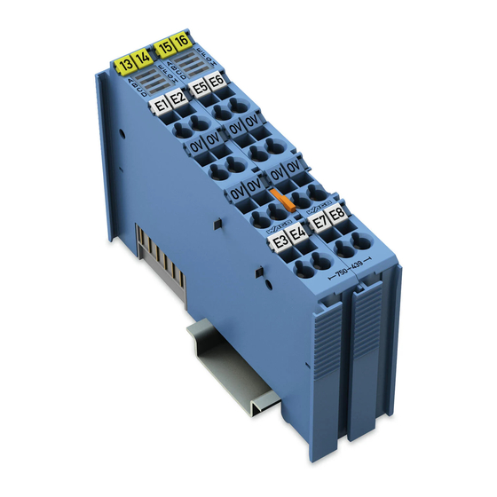
Device Description WAGO-I/O-SYSTEM 750 750-439 8DI NAMUR Ex i View Figure 1: View Table 4: Legend for Figure “View” Pos. Description Details See Section Marking possibility with Mini- Status LEDs “Device Description” > “Display Elements” Data contacts “Device Description” > “Connectors”... -
Page 17: Connectors
WAGO-I/O-SYSTEM 750 Device Description 750-439 8DI NAMUR Ex i Connectors 3.2.1 Data Contacts/Local Bus Communication between the fieldbus coupler/controller and the I/O modules as well as the system supply of the I/O modules is carried out via the local bus. The contacting for the local bus consists of 6 data contacts, which are available as self-cleaning gold spring contacts. -
Page 18: Power Jumper Contacts/Field Supply
The blade contacts are sharp-edged. Handle the I/O module carefully to prevent injury. Do not touch the blade contacts. The I/O module 750-439 has 2 self-cleaning power jumper contacts that supply and transmit power for the field side. The contacts on the left side of the I/O module are designed as blade contacts and those on the right side as spring contacts. -
Page 19: Cage Clamp
I/O module can be achieved even in the presence of interference acting on the signal cable. Shield Connection System for Electromagnetic Compatibility! The WAGO Shield Connection System offers a full range of accessories for maintaining electromagnetic compatibility (EMC)! Related information is available at www.wago.com. -
Page 20: Display Elements
Device Description WAGO-I/O-SYSTEM 750 750-439 8DI NAMUR Ex i Display Elements Figure 5: Display Elements Table 7: Legend for Figure “Display Elements” Channel Designation Function Indicator signal state Channel 1 / Status DI 1/Error DI 1 error Digital Input 1... -
Page 21: Operating Elements
WAGO-I/O-SYSTEM 750 Device Description 750-439 8DI NAMUR Ex i Operating Elements The I/O module 750-439 has no operating elements. Schematic Diagram Figure 6: Schematic Diagram Manual Version 1.3.0, valid from HW Version 03, SW Version 03... -
Page 22: Technical Data
Device Description WAGO-I/O-SYSTEM 750 750-439 8DI NAMUR Ex i Technical Data 3.6.1 Dimensions and Weight Table 8: Technical Data – Dimensions and Weight Width 24 mm Height 67.8 mm Length 100 mm Weight 95.6 g 3.6.2 Power Supply Table 9: Technical Data – Power Supply... -
Page 23: Inputs
WAGO-I/O-SYSTEM 750 Device Description 750-439 8DI NAMUR Ex i 3.6.4 Inputs Table 11: Technical Data – Inputs Number of digital inputs Signal type NAMUR Sensor connection 2-wire Input characteristic Switching amplifier per EN 60947-5-6 Signal current (0) NAMUR ≤ 1.2 mA Signal current (1) NAMUR ≥... -
Page 24: Explosion Protection
Device Description WAGO-I/O-SYSTEM 750 750-439 8DI NAMUR Ex i Table 12: Legend for Figure “Current-voltage Characteristic of the Control Input per EN 60947-5-6” Pos. Description Response range for changes in the switching state ΔI : 1.2 … 2.1 mA Response range for short circuit in the control circuit ΔR: 100 … 360 Ω... -
Page 25: Connection Type
WAGO-I/O-SYSTEM 750 Device Description 750-439 8DI NAMUR Ex i 3.6.6 Connection Type Table 14: Technical Data – Field Wiring ® Wire connection CAGE CLAMP Cross section 0.08 mm² … 2.5 mm², AWG 28 … 14 Stripped lengths 8 mm … 9 mm / 0.33 in Table 15: Technical Data –... -
Page 26: Approvals
Approvals More information about approvals. Detailed references to the approvals are listed in the document “Overview Approvals WAGO I/O SYSTEM 750”, which you can find via the internet under: www.wago.com DOWNLOADS Documentation System Description. The following approvals have been granted to 750-439 I/O modules:... - Page 27 [Temperature: B, Humidity: B, Vibration: B, EMC: B, Enclosure: A] More information about approvals. Detailed references to the approvals are listed in the document “Overview Approvals WAGO I/O SYSTEM 750”, which you can find via the internet under: www.wago.com DOWNLOADS Documentation System Description.
-
Page 28: Standards And Guidelines
Device Description WAGO-I/O-SYSTEM 750 750-439 8DI NAMUR Ex i Standards and Guidelines 750-439 I/O modules meet the following standards and guidelines: ATEX Directive 2014/34/EU Explosive atmosphere EN 60079-0 Devices – General requirements Explosive atmosphere IEC 60079-7 Equipment protection by increased safety "e"... - Page 29 WAGO-I/O-SYSTEM 750 Device Description 750-439 8DI NAMUR Ex i American National Standard – ANSI/ISA 12.12.01 for Nonincendive Electrical Equipment for Use in Class I and II, Division 2 and Class III. Division 1 and 2 Hazardous (Classified) Location EU EMC Directive...
-
Page 30: Process Image
“I/O Modules” included in the description concerning the process image of the corresponding coupler/controller. The I/O Module 750-439 provides the fieldbus coupler/controller 2 bytes in the input and output process image. The signal status of inputs DI 1 … DI 8 is transmitted to the fieldbus coupler/controller via input data byte D0, the error status via input data byte D1. -
Page 31: Table 20: Bit Combination With A Connected Sensor Functioning As A Make
WAGO-I/O-SYSTEM 750 Process Image 750-439 8DI NAMUR Ex i Fieldbus-specific evaluation of the errors (wire break, short circuit) is channel by channel via the status bits. The I/O module generates a generic code that the fieldbus coupler/controller implements. When sensor type NO (“Normally Open”, make contact) is enabled, the following... -
Page 32: Table 22: Output Byte D0 (Enable Sensor Type Nc)
Process Image WAGO-I/O-SYSTEM 750 750-439 8DI NAMUR Ex i Output byte D0 is used to determine whether a make contact or a break contact should be processed as sensor. Table 22: Output Byte D0 (Enable Sensor Type NC) Bit 7... -
Page 33: Table 23: Output Byte D1 (Diagnostic Status)
WAGO-I/O-SYSTEM 750 Process Image 750-439 8DI NAMUR Ex i Table 23: Output Byte D1 (Diagnostic Status) Bit 7 Bit 6 Bit 5 Bit 4 Bit 3 Bit 2 Bit 1 Bit 0 DIA_DIS DIA_DIS DIA_DIS DIA_DIS DIA_DIS DIA_DIS DIA_DIS DIA_DIS... -
Page 34: Mounting
Mounting WAGO-I/O-SYSTEM 750 750-439 8DI NAMUR Ex i Mounting Do not work when devices are energized! High voltage can cause electric shock or burns. Switch off all power to the device prior to performing any installation, repair or maintenance work. -
Page 35: Mounting Sequence
Always plug a bus end module (750-600) onto the end of the fieldbus node! You must always use a bus end module at all fieldbus nodes with WAGO I/O SYSTEM 750 fieldbus couplers or controllers to guarantee proper data transfer. -
Page 36: Inserting And Removing Devices
Mounting WAGO-I/O-SYSTEM 750 750-439 8DI NAMUR Ex i Inserting and Removing Devices 5.2.1 Inserting the I/O Module Position the I/O module in such a way that the groove and spring are connected to the preceding and following components. Figure 8: Inserting I/O Module (Example) Press the I/O module into the assembly until the I/O module snaps into the carrier rail. -
Page 37: Removing The I/O Module
WAGO-I/O-SYSTEM 750 Mounting 750-439 8DI NAMUR Ex i Once the I/O module has snapped into place, the electrical connections for the data contacts and power contacts (if any) to the head station or to the preceding and, if applicable, following I/O module are established. -
Page 38: Connect Devices
Only one conductor may be connected to each CAGE CLAMP Do not connect more than one conductor at one single connection! If more than one conductor must be routed to one connection, these must be connected in an up-circuit wiring assembly, for example using WAGO feed- through terminals. ®... -
Page 39: Power Supply Concept
WAGO-I/O-SYSTEM 750 Connect Devices 750-439 8DI NAMUR Ex i Power Supply Concept Ex i I/O modules shall only be supplied via Ex i 24 VDC power supply module! Ex i I/O modules shall only be operated with an Ex i 24 VDC power supply module. -
Page 40: Figure 12: Supply Principle Ex I
WAGO-I/O-SYSTEM 750 750-439 8DI NAMUR Ex i The Ex i I/O module (750-439) receives the 24 V voltage supply potential and the 0V potential for the field level from an upstream Ex i I/O module or from an Ex i power supply module via the power contacts designed as blade contacts. -
Page 41: Power Supply Concept For Marine Applications In Ex I
WAGO-I/O-SYSTEM 750 Connect Devices 750-439 8DI NAMUR Ex i Figure 13: Overvoltage Categories Table 25: Legend for Figure “Overvoltage Categories” Pos. Explanation Fieldbus coupler/controller Filter module (if required) Ex i supply module Ex i I/O modules End module Overvoltage categories and rated surge voltage see EN 61010-2-201. -
Page 42: Figure 14: Power Supply Concept For Marine Applications In Ex I - Class A (Shown With 750-624/Xxx-Xxx For Field 2)
Connect Devices WAGO-I/O-SYSTEM 750 750-439 8DI NAMUR Ex i Power Supply Concept for Marine Applications in Ex i Class A Figure 14: Power Supply Concept for Marine Applications in Ex i – Class A (shown with 750- 624/xxx-xxx for Field 2) Table 26: Legend for figure “Power Supply Concept for Marine Applications in Ex i –... -
Page 43: Figure 15: Power Supply Concept For Marine Applications In Ex I - Class B (Shown With 750-626/Xxx-Xxx For Field 2)
WAGO-I/O-SYSTEM 750 Connect Devices 750-439 8DI NAMUR Ex i Power Supply Concept for Marine Applications in Ex i Class B Figure 15: Power Supply Concept for Marine Applications in Ex i – Class B (shown with 750- 626/xxx-xxx for Field 2) Table 28: Legend for figure “Power Supply Concept for Marine Applications in Ex i –... -
Page 44: Connection Example
Connect Devices WAGO-I/O-SYSTEM 750 750-439 8DI NAMUR Ex i Connection Example Figure 16: Connection Example with 8 Sensors on Channel 1 to 8 Use shielded signal lines! Only use shielded signal lines. Only then can you ensure that the accuracy and interference immunity specified for the respective I/O module can be achieved even in the presence of interference acting on the signal cable. -
Page 45: Commissioning
750-439 8DI NAMUR Ex i Commissioning WAGO-I/O-CHECK The I/O Module 750-439 is supported by the WAGO-I/O-CHECK commissioning tool staring with version 03.21.01(01). After the node has been identified, the process values, the process values in “Monitor Mode” or “Control Mode” are first displayed using the generic inputs “750-4xx, 16DI / 16DO”. -
Page 46: E!Cockpit
The respective designations are displayed in the navigation tree of WAGO-I/O- CHECK and can be saved in the node file of WAGO-I/O-CHECK. e!COCKPIT The I/O-Modul 750-439 is supported by the e!COCKPIT commissioning tool, see the “2759-0101 e!COCKPIT” manual, Section “Operating” > … > “Performing a Systematic Input/Output Test (WAGO-I/O-CHECK)”. -
Page 47: Diagnostics
WAGO-I/O-SYSTEM 750 Diagnostics 750-439 8DI NAMUR Ex i Diagnostics Diagnostics via LED Indicators The display elements of the I/O modules provide information about possible statuses and cases of error. The table below contains the evaluation of the signaling: Table 31: Signal Evaluation for Each Channel, LED A-H... -
Page 48: Use In Hazardous Environments
WAGO-I/O-SYSTEM 750 750-439 8DI NAMUR Ex i Use in Hazardous Environments The WAGO I/O SYSTEM 750 (electrical equipment) is designed for use in Zone 2 hazardous areas and shall be used in accordance with the marking and installation regulations. The following sections include both the general identification of components (devices) and the installation regulations to be observed. -
Page 49: Marking Configuration Examples
WAGO-I/O-SYSTEM 750 Use in Hazardous Environments 750-439 8DI NAMUR Ex i Marking Configuration Examples 9.1.1 Marking for Europe According to ATEX and IECEx Figure 19: Marking Example per ATEX and IECEx Figure 20: Text Detail – Marking Example per ATEX and IECEx Manual Version 1.3.0, valid from HW Version 03, SW Version 03... -
Page 50: Table 32: Description Of The Marking Example Per Atex And Iecex
Use in Hazardous Environments WAGO-I/O-SYSTEM 750 750-439 8DI NAMUR Ex i Table 32: Description of the Marking Example per ATEX and IECEx Marking Text Description TUEV 07 ATEX 554086 X Approving authority or certificate numbers IECEx TUN 09.0001 X Dust... -
Page 51: Figure 21: Marking Example Of An Approved I/O Module Ex I Per Atex And
WAGO-I/O-SYSTEM 750 Use in Hazardous Environments 750-439 8DI NAMUR Ex i Figure 21: Marking Example of an Approved I/O Module Ex i per ATEX and IECEx Figure 22: Text Detail – Marking Example of an Approved I/O Module Ex i... -
Page 52: Table 33: Description Of The Marking Example Of An Approved I/O Module Ex I Per Atex And Iecex
Use in Hazardous Environments WAGO-I/O-SYSTEM 750 750-439 8DI NAMUR Ex i Table 33: Description of the Marking Example of an Approved I/O Module Ex i per ATEX and IECEx Marking Text Description TUEV 12 ATEX 106032 X Approving authority or... -
Page 53: Marking For The United States Of America (Nec) And Canada (Cec)
WAGO-I/O-SYSTEM 750 Use in Hazardous Environments 750-439 8DI NAMUR Ex i 9.1.2 Marking for the United States of America (NEC) and Canada (CEC) Figure 23: Marking Example According to NEC Figure 24: Text Detail – Marking Example According to NEC 500... -
Page 54: Figure 25: Text Detail - Marking Example For Approved Ex I I/O Module
Use in Hazardous Environments WAGO-I/O-SYSTEM 750 750-439 8DI NAMUR Ex i Figure 25: Text Detail – Marking Example for Approved Ex i I/O Module According to NEC 505 Table 35: Description of Marking Example for Approved Ex i I/O Module According to NEC 505... -
Page 55: Figure 27: Text Detail - Marking Example For Approved Ex I I/O Modules
WAGO-I/O-SYSTEM 750 Use in Hazardous Environments 750-439 8DI NAMUR Ex i Figure 27: Text Detail – Marking Example for Approved Ex i I/O Modules According to CEC 18 attachment J Table 37: Description of Marking Example for Approved Ex i I/O Modules According to CEC 18... -
Page 56: Installation Regulations
Use in Hazardous Environments WAGO-I/O-SYSTEM 750 750-439 8DI NAMUR Ex i Installation Regulations For the installation and operation of electrical equipment in hazardous areas, the valid national and international rules and regulations which are applicable at the installation location must be carefully followed. - Page 57 WAGO-I/O-SYSTEM 750 Use in Hazardous Environments 750-439 8DI NAMUR Ex i Explosive atmosphere occurring simultaneously with assembly, installation or repair work must be ruled out. Among other things, these include the following activities • Insertion and removal of components •...
-
Page 58: Special Notes Regarding Ul Hazardous Location
Use in Hazardous Environments WAGO-I/O-SYSTEM 750 750-439 8DI NAMUR Ex i 9.2.2 Special Notes Regarding UL Hazardous Location For UL Hazardous Location acc. to UL File E198726, the following additional requirements apply: • Use in Class I, Division 2, Group A, B, C, D or non-hazardous areas only •... -
Page 59: List Of Figures
Figure 16: Connection Example with 8 Sensors on Channel 1 to 8 ....44 Figure 17: Rename I/O Module ................45 Figure 18: Setting Options in WAGO-I/O-CHECK ..........46 Figure 19: Marking Example per ATEX and IECEx ..........49 Figure 20: Text Detail – Marking Example per ATEX and IECEx ......49 Figure 21: Marking Example of an Approved I/O Module Ex i per ATEX and IECEx ...................... -
Page 60: List Of Tables
List of Tables WAGO-I/O-SYSTEM 750 750-439 8DI NAMUR Ex i List of Tables Table 1: Revision History ..................5 Table 2: Number Notation ..................9 Table 3: Font Conventions ..................9 Table 4: Legend for Figure “View” ............... 16 Table 5: Legend for Figure “Power Jumper Contacts” ......... 18 ®... - Page 61 WAGO-I/O-SYSTEM 750 List of Tables 750-439 8DI NAMUR Ex i Table 36: Description of Marking Example for Approved Ex i I/O Modules According to NEC 506 ................54 Table 37: Description of Marking Example for Approved Ex i I/O Modules According to CEC 18 attachment J ............
- Page 62 WAGO Kontakttechnik GmbH & Co. KG Postfach 2880 • D - 32385 Minden Hansastraße 27 • D - 32423 Minden Phone: +49 571 887 – 0 Fax: +49 571 887 – 844169 E-Mail: info@wago.com Internet: www.wago.com...
Need help?
Do you have a question about the 750-439 and is the answer not in the manual?
Questions and answers