Table of Contents
Advertisement
Advertisement
Table of Contents

Subscribe to Our Youtube Channel
Related Manuals for Ametek Reichert Phoroptor VRx


Summary of Contents for Ametek Reichert Phoroptor VRx
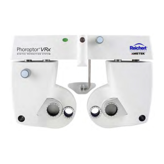
- Page 1 Phoroptor ® Digital Refraction System User’s Guide...
- Page 2 ©2017 AMETEK, Inc. Reichert, Reichert Technologies, Phoroptor, and ClearChart are registered trademarks of Reichert, Inc. AMETEK is a registered trademark of AMETEK, Inc. Bluetooth is a registered trademark of Bluetooth SIG. All other trademarks are property of their respective owners.
-
Page 3: Table Of Contents
Table of Contents Contents Warnings and Cautions ........................6 Symbol Information..........................8 Introduction ............................9 Indications for Use .........................9 Contra-Indications .........................9 Unpacking Instructions ........................10 Parts Identification ..........................12 Setup ..............................14 Connecting the Phoroptor VRx System Components ..............14 Leveling the Phoroptor Head .......................16 Face Shields ..........................17 Near Vision Rod and Card ......................18 Turn the Unit On and Off ......................18 Connect External Devices to the Phoroptor VRx................19... - Page 4 Table of Contents (continued) Programs ............................39 Creating a Program ........................39 Selecting Charts for Program Steps ....................40 Modifying a Step in the Program ....................41 Deleting a Step from your Program .....................41 Copying a Program already created ....................41 Exporting a Program ........................41 Importing a Program from an outside source (USB drive) ............42 Clearing a Program ........................42 Running a Program ........................43...
- Page 5 Table of Contents (continued) Freely Selectable Axis Adjustment ....................68 Cross Cylinder - Smart Test .......................69 Axis Adjustment ...........................69 Programmed Axis Adjustment .....................70 Freely Selectable Axis Adjustment ....................70 Programmed Cylinder Power Adjustment ..................71 Freely Selectable Cylinder Power Adjustment ................71 Cross Cylinder - Split Cyl Test ......................72 Axis Adjustment ...........................73 Cylinder Power Adjustment ......................73 Near Vision Test ..........................74...
-
Page 6: Warnings And Cautions
Warnings and Cautions Warnings and Cautions ® ® Reichert Technologies (Reichert ) is not responsible for the safety and reliability of this instrument when unauthorized dealers or persons assemble, disassemble, repair, or modify the instrument, or when a person does not use the instrument in accordance with this User’s Guide. WARNING: AN INSTRUCTION THAT DRAWS ATTENTION TO THE RISK OF INJURY OR DEATH. - Page 7 Warnings and Cautions (continued) Warnings and Cautions (continued) WARNING: PRIOR TO INSTALLING THE PHOROPTOR HEAD ONTO THE STAND ARM, VERIFY THAT THE ROD ON THE STAND ARM IS SECURE BEFORE ATTEMPTING TO INSTALL THE PHOROPTOR HEAD OR YOU MIGHT DAMAGE THE UNIT AND/OR INJURE THE PATIENT. WARNING: OTHER ELECTRICAL OR ELECTRONIC EQUIPMENT CAN INTERFERE WITH THE BLUETOOTH WIRELESS CONNECTION TRANSMITTERS OR RECEIVERS, EVEN IF THAT EQUIPMENT ALSO COMPLIES WITH CISPR EMISSIONS REQUIREMENTS.
-
Page 8: Symbol Information
Symbol Information Symbol Information The following symbols appear on the instrument. Consult Instructions for Use symbol indicating important operating and maintenance instructions included in this User’s Guide Caution symbol indicating important information and maintenance instructions included in this User’s Guide Type B Product Classification Protective Earth Alternating Current Power... -
Page 9: Introduction
Phoroptor VRx, contact your local authorized Reichert dealer, or contact our Customer Service department directly: Tel: 716-686-4500 Fax: 716-686-4555 Email: reichert.information@ametek.com Indications for Use The digital refractor Phoroptor VRx is designed for: • Subjective measurement of the refractive error of the eye. -
Page 10: Unpacking Instructions
Instrument Setup Unpacking Instructions Great care is taken to deliver your Phoroptor VRx to you intact. Please read this User’s Guide before operating the unit. We package the instrument in shipping containers to protect the instrument from damage during shipping. Please carefully remove the Phoroptor Head, Controller, Central Unit, and Accessories Box from the packaging material. - Page 11 Instrument Setup (continued) Unpacking Instructions (continued) 8. Remove the white cardboard Accessories Box. (Please refer to Figure IS-03.) Accessories Controller Figure IS-03, Packaging - Accessories Box Note: The Accessories Box includes a power cord, cable for the Phoroptor Head, Bluetooth antenna for the Central Unit, near vision card and illuminator, face shields, dust covers for the Phoroptor Head and Controller, and User’s Guide.
-
Page 12: Parts Identification
Instrument Setup (continued) Parts Identification One of the following Phoroptor VRx Systems is in the shipping container, depending on the system specifications you ordered: Description – System Catalog Number Phoroptor VRx, Middle Mount 16241 Includes • Phoroptor VRx Head Assembly 16212 •... - Page 13 Instrument Setup (continued) Parts Identification (continued) Controller Central Unit 13 14 22 21 Phoroptor Head 16 15 Figure IS-06, Parts Identification 1. Illuminated Bubble Level 14. Wireless Antenna 2. Convergence Lever 15. Transfer Port 3. Threaded Pin for Near Vision Rod 16.
-
Page 14: Setup
Instrument Setup (continued) Setup Connecting the Phoroptor VRx System Components WARNING: APPLY RATED INPUT VOLTAGE TO THE UNIT AS INDICATED ON THE DATA PLATE TO PREVENT DAMAGE TO THE INSTRUMENT AND/OR INJURY TO THE OPERATOR OR PATIENT. WARNING: CAREFULLY ARRANGE THE CABLES FOR THE UNIT AND ACCESSORIES, SO THE CABLES DO NOT PRESENT A TRIPPING HAZARD TO THE EXAMINER OR A DANGER TO THE PATIENT. - Page 15 Instrument Setup (continued) Setup (continued) Please refer to the Connection Diagram in Figure IS-07 for plug and cable layout. Phoroptor Head Projector or Digital Acuity System Power Central Unit Controller Figure IS-07, Connection Diagram 16241-101 Rev. D...
-
Page 16: Leveling The Phoroptor Head
Instrument Setup (continued) Setup (continued) Leveling the Phoroptor Head After you install the Phoroptor Head onto the stand and connect all the wires, check to see if the Phoroptor Head requires leveling. If the Phoroptor Head is not level, adjust it by rotating the Thumb Screw on the top of the Phoroptor Head. -
Page 17: Face Shields
Instrument Setup (continued) Setup (continued) Face Shields Face shields are provided for the patient side of the Phoroptor VRx Head to help keep the equipment clean. Magnets hold the face shields in place, enabling the user to easily remove, clean, and replace the shields. -
Page 18: Near Vision Rod And Card
Instrument Setup (continued) Setup (continued) Near Vision Rod and Card The near vision testing accessories include a rod, reading card, and a card illuminator. The reading card is attached to the card illuminator. Place three AAA batteries provided in the card illuminator. Slide the card illuminator onto the near vision rod and position it at the desired reading distance. -
Page 19: Connect External Devices To The Phoroptor Vrx
Instrument Setup (continued) Connect External Devices to the Phoroptor VRx The basic system setup contains three items programmed to interact with each other: the Phoroptor Head, the Central Unit, and the Controller. The Central Unit directs communication between the Phoroptor Head, Controller, and other external devices, while the Controller acts as the user interface and controls the Phoroptor Head and the Input/Output of data. -
Page 20: Connect External Devices With Reichert Wireless Serial Adapters
Instrument Setup (continued) Connect External Devices with Reichert Wireless Serial Adapters Bluetooth Dongle Reichert designed a proprietary Bluetooth serial adapter to connect external devices to the Phoroptor VRx. In order to establish wireless communications between the Phoroptor VRx and an external device, you must first configure the Reichert Bluetooth dongle for a specific Central Unit port (e.g., Projector, EMR, Instrument #1) and program the adapter with the serial communications parameters (baud rate, data bits, parity, stop bits) required by the external device. - Page 21 Instrument Setup (continued) Connect External Devices with Reichert Wireless Serial Adapters (continued) 11. On the Port Settings panel tap the Pair button. 12. The LED indicator on the Bluetooth dongle will first blink about once every second. Once the connection has been established, the LED indicator will remain on constantly. Note If the connection was successfully paired, the word “Connected”...
- Page 22 Instrument Setup (continued) Connect External Devices with Reichert Wireless .. (Continued) ClearChart 4 Bluetooth USB Reichert has a Bluetooth USB option to connect a ClearChart 4, 4X or 4P to the Phoroptor VRx. In order to establish wireless communications between the Phoroptor VRx and a ClearChart, you must first pair the Projector port to the Bluetooth USB adapter: 1.
- Page 23 Instrument Setup (continued) ClearChart 4 Bluetooth USB ( Continued 7. Install the Bluetooth USB into the ClearChart. Then power ON the ClearChart. Note: The Bluetooth USB must be installed in the Clearchart before the ClearChart is powered ON or the Bluetooth USB will not be paired properly. Figure IS-14C, Bluetooth Installed 8.
-
Page 24: Connect Acuity Systems To The Phoroptor Vrx
Instrument Setup (continued) ® ® Connect ClearChart 2 or ClearChart 3 Series to the Phoroptor VRx Auto Projector Systems are directly connected to the Projector port on the Central Unit using a cable or a wireless Bluetooth dongle, according to the cables specified in Appendix A. Wired communication between the ClearChart 2 or ClearChart 3P and the Phoroptor VRx requires connection of a cable, according to the cables specified in Appendix A. -
Page 25: Connecting Multiple Phoroptor Vrx Units
Instrument Setup (continued) Connect Multiple Phoroptor VRx External Devices 1. Connect Lensmeters and Auto Refractors to either of the Instrument ports on the Central Unit using a serial cable designated for use with a specific manufacturer’s external device. (Please refer to Appendix A for a list of different manufacturer’s external devices that communicate with the Phoroptor VRx and the specifications of serial cables used to connect these devices.) Note: Auxiliary external devices can also communicate wirelessly with the Phoroptor VRx. - Page 26 Instrument Setup (continued) Connect Multiple Phoroptor VRx External Devices (continued) 1. Setup the Auto Refractor and Lensmeter to communicate with the Phoroptor VRx closest to that location, using wired or wireless connections to the Instrument 1 and Instrument 2 ports. 2.
-
Page 27: User Guide Standards
Instrument Setup (continued) User Guide Standards The Phoroptor VRx performs all refraction methods. The user selects the order of the examination steps. Windows CE is the operating system of the Phoroptor VRx. Activate the functions using the Phoroptor VRx Controller Keypad buttons, the Control Knob, or the Controller Touchscreen. Control Knob Use Turn the Control Knob clockwise or counterclockwise to change the numeric values and the selection of fields as follows:... -
Page 28: Controller Keypad
Instrument Setup (continued) Controller Keypad 10 11 26 25 23 22 Figure IS-21, Controller Keypad 1. C—Clear data 17. Enter Key for Cross Cylinder Tests 2. AR—Auto Refractor 18. Green button for Split Prism Test 3. LM—Lensmeter 19. L—Left eye aperture 4. -
Page 29: Icon Description
Instrument Setup (continued) Icon Description 1. Date and Time 2. Exam Time Figure IS-22, Display Screen 3. Active Lenses/Filters 4. Pupillary Distance 5. Options/Setup Menu 6. Display Illumination adjustment 7. Auto Refractor Data (Entered manually or electronically.) 8. Lensmeter Data (Entered manually or electronically.) 9. -
Page 30: Auxiliary Lenses Or Filters
Instrument Setup (continued) Icon Description (continued) Auxiliary Lenses or Filters Figure IS-23, Auxiliary Lenses Screen 1. Touch RED/GREEN/POLARIZED Lens Filters, located on the right side of the screen, just below the illumination adjustment icons, to access the auxiliary lenses and filters. (Please refer to Figure IS-22, #10.) Note: The lenses and filters appear in the selection bar at the bottom of the screen. -
Page 31: Controller Button Descriptions And Effects
Instrument Setup (continued) Icon Description (continued) Controller Button Descriptions and Effects The following explains Controller icon operation and effects on the Phoroptor Head: Open Occluder Aperture - Touch to open the aperture of the occluded eye. If both eyes are occluded, touch it once to open one eye, and again to open both apertures. -
Page 32: Options/Setup Menu
Instrument Setup (continued) Options/Setup Menu The Options/Setup Menu is only accessible from the Main screen. The following is a summary of the Options Menu and all of the corresponding drop-down lists that coincide with each category in the Options Menu. Touch OPTIONS in the top right corner of the screen to access the Options screen. ↓... -
Page 33: Settings
Instrument Setup (continued) Options/Setup Menu (continued) Settings 1. Open the OPTIONS/SETUP MENU to display the Settings screen. 2. Touch the box for each setting to customize settings. (Please refer to Figure IS-24.) 3. Touch the preferred option in the drop-down list to select it. Note: The Options categories are described in the following pages. -
Page 34: Cylinder
Instrument Setup (continued) Options/Setup Menu (continued) Cylinder +/- Use this option to change the default cylinder power to one of the following: • Plus Cylinder only (“+”) • Minus Cylinder only (“-”) • Plus and Minus Cylinder (“+/-”) Axis 0/180 This option selects 0º... -
Page 35: Xcyl Auto
Instrument Setup (continued) Options/Setup Menu (continued) Binocular Only This option allows you to leaves both eye apertures open during all far vision tests when selected to ON. Figure IS-24A, Settings Menu - CC Button CC Button Option to choose either the final refraction data or the imported REF data on the display. Refer to Figure IS-24A. -
Page 36: Date Format
Instrument Setup (continued) Options/Setup Menu (continued) Date Format The options are: • YMD (Year-Month-Day) • MDY (Month-Day-Year) • DMY (Day-Month-Year) • MDY TEXT (Month-Day-Year, displayed in the format “<name of the month>, <day as number>, <year as 4-digit number>”.) Time format The options are: •... - Page 37 Instrument Setup (continued) Options/Setup Menu (continued) Reset Exam The Reset Exam drop down list sets the option to reset the exam data to the default setting after an exam is exported. Refer to Figure IS-24B. Figure IS-24B, Settings Menu - CC Button EMR Section The following are the options of which data to send to an Electronic Medical Records (EMR) system: •...
- Page 38 Instrument Setup (continued) Options/Setup Menu (continued) Autoload The following are the options to perform an autoload function of imported data. Refer to Figure IS-24C. • AR - Autoloads the autorefractor data • LM - Autoloads the lensmeter data • REF - Autoloads the imported refraction data Figure IS-24C, Settings Menu - CC Button Printer Section From the Format drop-down list, choose which data to print:...
-
Page 39: Programs
Instrument Setup (continued) Programs You can record refraction step sequences in a program file that is selected and run from the main screen. (Please refer to Figure IS-25.) Figure IS-25, Program Screen Creating a Program 1. Touch the NUMBER in the Program Selection panel to designate the program you want to setup. 2. -
Page 40: Selecting Charts For Program Steps
Instrument Setup (continued) Programs (continued) Figure IS-26, Sphere Adjustment Chart Selection Selecting Charts for Program Steps The Sphere Adjust, Cyl Adjust, and Axis Adjust steps allow you to associate a specific chart with that step. (Please refer to Figure IS-26.) 1. -
Page 41: Modifying A Step In The Program
Instrument Setup (continued) Programs (continued) Modifying a Step in the Program 1. Touch the step you want to modify in the Program Listing panel. 2. Touch MODIFY in the menu bar at the bottom of the screen. 3. Make any desired changes to the selected Mode, Eye, or Chart. Deleting a Step from your Program 1. -
Page 42: Importing A Program From An Outside Source (Usb Drive)
Instrument Setup (continued) Programs (continued) Figure IS-27, USB Drive Importing a Program from an outside source (USB drive) 1. Insert the outside source (USB drive) from which you want to import the program. (Please refer to Figure IS-27.) 2. Touch the Number of the program into which you want to import the program steps. Note: The imported program number must match the program number where it is placed (e.g., Program 1 from one VRx must be imported into Program 1 of another VRx unit). -
Page 43: Running A Program
Instrument Setup (continued) Programs (continued) Running a Program In the main screen, the programs you created display in the Run Program panel in the lower right corner of the screen. (Please refer to Figure IS-28.) To run a program: 1. Touch the program number you want to run at the bottom right corner of the screen. Note: The first step of the program automatically begins. -
Page 44: Charts
Instrument Setup (continued) Charts Touch CHARTS in the menu bar at the bottom of the Settings Menu screen (Please refer to Figure IS-24 on page 32). Available Charts Default Preferred Charts Charts Figure IS-29, Charts Screen The top of the Charts screen contains all available charts from which to choose. The lower left section of the screen contains your preferred charts, which are selectable from the Main screen. -
Page 45: Chart For Optotypes
Instrument Setup (continued) Charts (continued) Chart for Optotypes If you select an optotype chart, the Chart Options dialog box appears. Figure IS-31, Chart Options Note: The Chart Options dialog box allows you to select the optotype size (using the + and - icons) and change the direction and number of lines displayed. -
Page 46: Xcyl Default Charts
Instrument Setup (continued) Charts (continued) XCyl Default Charts The XCYL Default Charts selections allow the user to select specific charts that display when checking for Astigmatism correction, and adjusting Axis and Cylinder power in any of the Cross Cylinder tests. Note: Please follow the instructions in the Selecting a Default Chart section of this guide to select the default charts for the Astigmatism (Astig), Axis, and Cylinder Power adjustments. -
Page 47: Ports
Instrument Setup (continued) Ports Touch PORTS in the menu bar at the bottom of the Settings Menu screen. (Refer to Figure IS-24 in the Options/Setup Menu section of this manual.) Figure IS-32, Ports Screen The Ports screen allows you to connect external devices the Phoroptor VRx. The ports available on the Ports screen match the ports at the back of the Central Unit. -
Page 48: Service Menu
Instrument Setup (continued) Service Menu Touch SERVICE in the menu bar at the bottom of the Settings Menu screen to display the Service (System Information) screen. (Please refer to Figure IS-24 on page 32.) Figure IS-33, Service Menu System Information The Service Information section lists the following information: (Please refer to Figure IS-33.) •... -
Page 49: Set Date/Time
Instrument Setup (continued) Service Menu (continued) Set Date/Time 1. Touch + or - in the Set Date/Time box to change the date and time. (Please refer to Figure IS- 33.) 2. Touch SET to set the date and time. Phoroptor Test Figure IS-34, Phoroptor Test Screen 1. -
Page 50: Keyboard Test
Instrument Setup (continued) Service Menu (continued) Keyboard Test Figure IS-35, Keyboard Test Screen Button Section 1. Touch KEYBOARD TEST to begin the test, which ensures that all of the Keypad buttons function properly. (Please refer to Figure IS-35.) 2. Press each Keypad button to ensure all buttons function properly. 3. -
Page 51: Import Settings And Export Settings
Instrument Setup (continued) Service Menu (continued) Keyboard Test (continued) Sound Control Test The Sound Control section of the Keyboard Test window allows you to test the functioning of the sounds emitted by the Controller when performing various functions. The following list explains the sounds: •... -
Page 52: Instructions For Use
Instructions for Use Instructions for Use Introduction Align the Phoroptor Head with the patient to ensure you are taking reliable measurements. Once the Phoroptor Head is powered on and completes an initialization process, you can then align it and take measurements. - Page 53 Instructions for Use (continued) Aligning the Phoroptor Head (continued) Pupillary Distance The next adjustment is the Pupillary Distance (PD). Using the Controller, adjust the pupillary distance between the right and left apertures on the Phoroptor Head. You can adjust the PD either monocularly or binocularly.
- Page 54 Instructions for Use (continued) Aligning the Phoroptor Head (continued) Height Level of Eyes Adjust the Refractor so that the height of each side is level with the respective patient’s eye. 1. Center the left aperture in front of the patient’s left eye.
-
Page 55: Data Input
Instructions for Use (continued) Data Input Now that you have aligned the Phoroptor Head, you can begin to take measurements. You can import previous measurements as a starting point for a refraction. To do so, you need a basic understanding of the storing and importing of data. -
Page 56: Entering Data Manually
Instructions for Use (continued) Data Input (continued) Drop-Down Entering Data Manually List Figure IU-09, Data Input Drop-Down List Perform the following steps to enter data manually: (Please refer to Figure IU-09.) 1. Touch the drop-down list in the main display area to open a drop-down list of different data sets. 2. -
Page 57: Inputting Data Electronically
Instructions for Use (continued) Data Input (continued) Entering Data Manually (continued) 4. Turn the CONTROL KNOB to enter the values for the data fields (Sphere, Cylinder, Axis, Add etc.). 5. Press the CONTROL KNOB to move to the next data field. 6. - Page 58 Instructions for Use (continued) Data Input (continued) Inputting Data Electronically (continued) Direct Connection The measurement data from the Lensmeter and Auto Refractor directly populates the LM and AR data fields in the Controller display. The data transfer takes place when the user presses the data output buttons on each external device.
-
Page 59: Adjust Values
Instructions for Use (continued) Adjust Values Now that you aligned the Phoroptor Head and imported data, start the refraction. Adjusting a Refraction From Previously Saved, Transferred, or Input Data 1. Touch the drop-down list in the main display area or press the AR or LM button on the keypad to select the data you want to use to start the refraction (e.g., LM, AR). -
Page 60: Sphere
Instructions for Use (continued) Adjust Values (continued) Sphere 1. Activate the Sphere value field using one of the following two methods: Using the Touch Screen Touch the S box in the main display area of the screen to activate the Sphere value field for •... -
Page 61: Cylinder
Instructions for Use (continued) Adjust Values (continued) Cylinder 1. Activate the Cylinder value field using one of the following two methods: Using the Screen Touch the C box in the main display area of the screen to activate the Cylinder value field for •... -
Page 62: Sphere And Cylinder - Maintaining Spherical Equivalent
Instructions for Use (continued) Adjust Values (continued) Sphere and Cylinder - Maintaining Spherical Equivalent You can adjust both the Sphere and Cylinder values simultaneously to maintain the spherical equivalent. This adjustment is done monocularly and binocularly. 1. Press the C button, or touch C or the data field next to the C on the screen when Cylinder is already selected. -
Page 63: Axis
Instructions for Use (continued) Adjust Values (continued) Axis 1. Use one of the following two methods to activate the desired Axis value field: Using the Screen Touch the A box in the main display area of the screen to activate the Axis value field for •... -
Page 64: Near Vision Addition
Instructions for Use (continued) Adjust Values (continued) Near Vision Addition 1. Lower the Near Vision Rod and Card to activate the Near Vision Addition (ADD) value field using one of the following two methods: Lowering the Near Vision Rod and Card automatically converges the Phoroptor, highlights the ADD data fields in the screen, and darkens the Acuity Chart screen. -
Page 65: Cross Cylinder
Instructions for Use (continued) Cross Cylinder The Cross Cylinder function enables: • Examination for Astigmatism. • Axis adjustment. • Cylinder power adjustment. 1. Touch XCyl in the menu bar at the bottom of the main screen to activate the Cross Cylinder function. -
Page 66: Cross Cylinder - Smart/Manual/Split Cyl Test
Instructions for Use (continued) Cross Cylinder - Smart/Manual/Split Cyl Test If the XCyl Mode setting is “User Select,” three test options display. MANUAL - Refine Axis in 1°, 5°, or 10° increments, and adjust Cylinder in ±0.25 D, ±0.50 D, •... -
Page 67: Cross Cylinder - Manual Test
Instructions for Use (continued) Cross Cylinder - Manual Test Figure IU-19, Cross Cylinder - Manual Test Screen The Manual Cross Cylinder test allows the user to refine Axis in 1°, 5°, or 10° increments, and adjust Cylinder in ±0.25 D, ±0.50 D, or ±1.00 D increments. (Please refer to Figure IU-19.) •... -
Page 68: Freely Selectable Axis Adjustment
Instructions for Use (continued) Cross Cylinder - Manual Test (continued) 4. Turn the CONTROL KNOB to present position 1 and position 2 to the patient. The direction of the Axis change is indicated in the lens aperture at the top of the screen. 5. -
Page 69: Cross Cylinder - Smart Test
Instructions for Use (continued) Cross Cylinder - Smart Test Figure IU-20, Cross Cylinder - Smart Test Screen Axis Adjustment 1. Touch XCyl on the menu bar at the bottom of the main screen. 2. Touch SMART to begin the Smart Cylinder test. •... -
Page 70: Programmed Axis Adjustment
Instructions for Use (continued) Cross Cylinder - Smart Test (continued) Programmed Axis Adjustment 1. Turn the CONTROL KNOB to change the Axis value in pre-programmed steps. Note: The degree of the first change depends on the Cylinder power. The higher the cylinder power, the smaller the change: Cylinder Power First Alteration... -
Page 71: Programmed Cylinder Power Adjustment
Instructions for Use (continued) Cross Cylinder - Smart Test (continued) Programmed Cylinder Power Adjustment 1. Turn the CONTROL KNOB to adjust the Cylinder power. 2. Present the patient with positions 1 and 2. • The Cylinder power adjustment is performed in pre-programmed steps. •... -
Page 72: Cross Cylinder - Split Cyl Test
Instructions for Use (continued) Cross Cylinder - Split Cyl Test Figure IU-21, Cross Cylinder - Split Cyl Test Screen The Split Cyl Cross Cylinder test allows the patient to see two test charts at the same time when adjusting Axis and Cylinder, making it easier for the patient to compare different Axis positions and Cylinder power values. -
Page 73: Axis Adjustment
Instructions for Use (continued) Cross Cylinder - Split Cyl Test (continued) Axis Adjustment 4. Touch the screen icon at the bottom left of the screen that indicates the degree of Axis change. • The degree of Axis change increments are 1°, 5°, or 10°. •... -
Page 74: Near Vision Test
Instructions for Use (continued) Near Vision Test If required, perform a Near Vision test with a test chart on a Near Vision rod. 1. Insert the Near Vision rod and test chart into the Convergence Lever on the bridge of the Phoroptor Head if it not already in place. -
Page 75: Fused Cross Cylinder Test
Instructions for Use (continued) Near Vision Test (continued) The Near Vision screen provides you with three modes of operation, detailed in the following sections: (Please refer to Figure IU-22.) Figure IU-22, Cross Cylinder - Near Vision Test Screen Fused Cross Cylinder Test 1. - Page 76 Instructions for Use (continued) Near Vision Test (continued) Fused Cross Cylinder Test (continued) 6. Touch SET ADD to set the patient’s Add value to that determined by the Fused Cross Cylinder test. Figure IU-23, Fused XCyl Test 16241-101 Rev. D...
-
Page 77: Nra/Pra Test
Instructions for Use (continued) Near Vision Test (continued) NRA/PRA Test You can also determine Near Vision Addition by measuring Negative Relative Accommodation (NRA) and Positive Relative Accommodation (PRA). The order of the test depends on the settings you selected in the Options/Setup Menu, either NRA/PRA or PRA/NRA. 1. -
Page 78: Amplitude Of Accommodation Test
Instructions for Use (continued) Near Vision Test (continued) Amplitude of Accommodation Test 1. Touch the ACCOMMODATION screen icon to measure the Amplitude of Accommodation or Accommodative Response. Note: Amplitude of Accommodation is measured monocularly. 2. Turn the CONTROL KNOB to add minus (-) power to the right eye (using the patient’s Near Vision addition as the starting point), until the patient states that the target blurs. -
Page 79: Prism Testing
Instructions for Use (continued) Prism Testing Prism lenses are built separately into the Phoroptor VRx and move in automatically when the prism test is engaged. Note: Not all models of the Phoroptor VRx come with prism compensators. 1. Press the PRISM button, or touch PRISM, to begin the Prism test. Note: The prism compensators automatically slide into place. -
Page 80: Horizontal Prism - Right Eye
Instructions for Use (continued) Prism Testing (continued) Horizontal Prism - Right Eye • Turn the CONTROL KNOB left to add BO prism in 0.25 D increments. • Turn the CONTROL KNOB right to add BI prism in 0.25 D increments. Horizontal Prism - Left Eye •... -
Page 81: Automated Prism Test - Phorias, Vergences
Instructions for Use (continued) Prism Testing (continued) Automated Prism Test - Phorias, Vergences When you activate the Prism function, two different automated test options appear at the bottom of the screen: Phoria and Vergence. • Touch PHORIA to sequence through a series of automated steps for measuring Phorias at distance or near. - Page 82 Instructions for Use (continued) Prism Testing (continued) Horizontal Phorias Test 1. Select an appropriate test chart of a single vertical line of optotypes or a single optotype. (Please refer to Figure IU-27.) 2. Verify that the patient can see two images, one up and one down. 3.
-
Page 83: Phoria Testing - Near
Instructions for Use (continued) Prism Testing (continued) Phoria Testing - Near 1. Lower the reading rod to converge the Phoroptor to measure Near vision horizontal phorias. 2. Press the PRISM button, or touch PRISM. 3. Touch PHORIA to begin the test. 4. - Page 84 Instructions for Use (continued) Prism Testing (continued) Figure IU-30, Power of Divergence - Blur Break Figure IU-31, Power of Divergence - Recover Power of Divergence The Vergence test automatically advances to measuring Power of Divergence after determining Power of Convergence. If you do not want to perform this test, touch SKIP to advance. (Please refer to Figures IU-30 &...
- Page 85 Instructions for Use (continued) Prism Testing (continued) Figure IU-32, Power of Convergence - Blur Break Figure IU-33, Power of Convergence - Recover Power of Convergence 1. Set the acuity chart to a single vertical line of optotypes at or near the patient’s visual acuity. (Please refer to Figures IU-32 &...
- Page 86 Instructions for Use (continued) Prism Testing (continued) Infravergence and Supravergence can now be measured in each eye. Figure IU-34, Infravergence - Break Figure IU-35, Infravergence - Recover Infravergence 1. Enter BD prism slowly, until the patient sees two images. (Please refer to Figures IU-34 & IU-35.) 2.
- Page 87 Instructions for Use (continued) Prism Testing (continued) Figure IU-36, Supravergence - Break Figure IU-37, Supravergence - Recover Supravergence 1. Enter BU prism slowly, until the patient sees two images. (Please refer to Figures IU-36 & IU-37.) 2. Press the CONTROL KNOB, or touch BREAK. 3.
-
Page 88: Vergence Testing Or Fusion Range Measurement - Near
Instructions for Use (continued) Prism Testing (continued) Vergence Testing or Fusion Range Measurement - Near Measure vergence for near vision using the following steps: 1. Lower the reading rod to converge the Phoroptor. 2. Press the PRISM button, or touch PRISM. 3. -
Page 89: Binocular Balance With Prisms
Instructions for Use (continued) Prism Testing (continued) Binocular Balance with Prisms Use binocular balance with prism to determine if the monocular VAs are the same. (Please refer to Figures IU-38 & IU-39.) 1. Press the BB button, or touch BB on the main screen, to begin the Binocular Balance prism test. 2. -
Page 90: Vertex Distance Calculator
Instructions for Use (continued) Vertex Distance Calculator The Vertex Distance Calculator converts the Subjective refraction data to different values for each vertex distance. (Please refer to Figure IU-40.) Figure IU-40, Vertex Distance Calculator You can: • Access the Vertex Distance Calculator by touching VD on the menu bar, which is located at the bottom of the screen. -
Page 91: Saving Visual Acuity - Distance
Instructions for Use (continued) Saving Visual Acuity - Distance You can save visual acuity for monocular and binocular vision for both unaided and aided visual acuity. (Please refer to Figures IU-41 & IU-42.) Figure IU-41, Unaided Visual Acuity Figure IU-42, Aided Visual Acuity Right Eye 1. -
Page 92: Saving Refraction Data
Instructions for Use (continued) Saving Refraction Data Store the measurements temporarily as Final, Mem 1, Mem 2, or Mem 3, or leave the data as Subjective, once the values for a refraction are completed. Storing different data in Mem 1, Mem 2, or Mem 3 allows the option of comparing different refraction data you are considering for your patient’s prescription. -
Page 93: Comparing Refraction Data
Instructions for Use (continued) Comparing Refraction Data One of the advantages of a digital refractor is the ability to quickly and easily compare different refractions with the push of a button, enabling patients to see the difference between their old and new prescriptions, or the difference between two possible prescriptions. -
Page 94: Data Output - Emr
Instructions for Use (continued) Data Output - EMR It is essential to either send the Final refraction data to an EMR system or the printer before clearing data and preparing for the next patient. The Final refraction data is not stored in the Phoroptor VRx, so it cannot be recalled for reference at a later time. -
Page 95: Emr Output Options
Instructions for Use (continued) Data Output - EMR (continued) After the exam is completed and the Data Output options are set, press the OUT button, or touch the OUT icon to transfer the data to an EMR system. Refer to Figure IU-43 and the illustration below. Note: The default data that is sent to the EMR system or the printer is Final refraction data. -
Page 96: Data Output - Printing
Instructions for Use (continued) Data Output - Printing 1. Connect an MCP1000 printer to the system. Refer to Figure IS-06 for the connection port. 2. Select the Device driver in the Ports Settings panel and touch APPLY. Note: If using a wireless connection, configure the port for a wireless setup and pair a Bluetooth adapter. -
Page 97: Printer Data Output
Instructions for Use (continued) Data Output - Printing (continued) Printer Output Options The options for Printer Output are the following: • Phoroptor VRx - Sends Phoroptor VRx final refraction data and, optionally, subjective refraction data and binocular test results • Phoroptor VRx Exp - Sends Phoroptor VRx final refraction data and, optionally, subjective refraction data and binocular test results plus auto-refractor and lensometer data, if available •... -
Page 98: Clearing Data
Instructions for Use (continued) Clearing Data Press the C Keypad button, or touch CLEAR, to view the options for clearing data. Figure IU-47, Clearing Data Clearing All Data 1. Press the C button, or touch CLEAR. (Please refer to Figure IU-47.) 2. - Page 99 Instructions for Use (continued) Clearing Data (continued) Initiate the action to clear data by pressing the C button or touching CLEAR on the menu bar at the bottom of the screen. Then touch the data you want to delete as described below. Clearing Individual Data Groups 1.
-
Page 100: Cleaning And Maintenance
Cleaning and Maintenance Cleaning and Maintenance WARNING: ANY REPAIR OR SERVICE TO THIS INSTRUMENT MUST BE PERFORMED BY EXPERIENCED PERSONNEL OR DEALERS THAT ARE TRAINED BY REICHERT SO THAT CORRECT OPERATION OF THIS INSTRUMENT IS MAINTAINED. WARNING: ALWAYS UNPLUG THE POWER CORD BEFORE CLEANING ANY SURFACE ON THE INSTRUMENT. CAUTION: INGRESS PROTECTION CLASSIFICATION FOR THE AUTO PHOROPTOR HEAD IS IP2X, WHILE THE CENTRAL UNIT AND CONTROLLER ARE IP3X. - Page 101 Cleaning and Maintenance (continued) Cleaning and Maintenance (continued) Forehead Rest Cleaning and Disinfection For hygienic reasons, you can clean the Forehead Rest with a clean cloth moistened with a mild detergent solution (1 cc of liquid dish soap to one liter of clean, filtered water (filtered below 5 microns)). Note: If the Forehead Rest must be sanitized, you can use a 70% isopropyl alcohol wipe.
-
Page 102: Troubleshooting
Troubleshooting Troubleshooting Only those errors indicated on the display are directly important to the user and are listed below. In case of support requests, please refer to the Error Log File (OPTIONS - Service - Show Error Log File) where you will find a detailed listing of all errors, warnings, and status messages. - Page 103 Troubleshooting (continued) Troubleshooting (continued) Error Source Probable Cause Solution No image in the display • Failure of fuses on the cable plug of • Exchange the fuses on the cable plug the central unit. of the central unit. despite switched-on unit. •...
-
Page 104: Specifications
Specifications Specifications REF 16241 / 16242 Physical Dimensions Phoroptor Head Spherical Effects ....................+17.75 to -22.25 D Steps ........................... 0.25 and 1.0 D Cylinder Power ......................-8.0 to +8.0 D Steps ........................... 0.25 and 1.0 D Axis Adjustment ........................0° to 180° Steps .......................... - Page 105 Specifications (continued) Environmental: The environmental conditions are as follows: Operating: 55° C Temperature: 10° to 35° C (50° to 95° F) -10° C Relative Air Humidity: 30 to 90% Air Pressure: 80 kPa to 106 kPa Transportation and Storage: Temperature: -10° to 55° C (14° to 131° F) 106 kPa Relative Air Humidity: 10 to 95% Air Pressure: 70 kPa to 106 kPa...
-
Page 106: Guidance Tables
Guidance Tables Guidance Tables Table 201 – Guidance and Manufacturer’s Declaration Electromagnetic Emissions All Equipment and Systems Guidance and Manufacturer’s Declaration – Electromagnetic Emissions The Phoroptor VRx is intended for use in the electromagnetic environment specified below. The customer or user of the Phoroptor VRx should ensure that it is used in such an environment. - Page 107 Guidance Tables (continued) Table 202 – Guidance and Manufacturer’s Declaration Electromagnetic Immunity All Equipment and Systems Guidance and Manufacturer’s Declaration – Electromagnetic Immunity The Phoroptor VRx is suitable for use in electromagnetic environment specified below. The customer or user of the Phoroptor VRx should ensure that it is used in such an environment. Immunity IEC 60601 Compliance...
- Page 108 Guidance Tables (continued) Table 204 – Guidance and Manufacturer’s Declaration Electromagnetic Immunity Equipment and Systems that are NOT Life-supporting Guidance and Manufacturer’s Declaration – Electromagnetic Immunity The Phoroptor VRx is intended for use in the electromagnetic environment specified below. The customer or user of the Phoroptor VRx should ensure that it is used in such an environment.
- Page 109 Guidance Tables (continued) Table 206 – Recommended Separation Distances between Portable and Mobile RF Communications Equipment and the Phoroptor VRx for ME Equipment and ME Systems that are NOT Life-supporting. Guidance and Manufacturer’s Declaration - Electromagnetic Immunity Recommended Separation Distances for between Portable and Mobile RF Communications Equipment and the Phoroptor VRx The Phoroptor VRx is intended for use in the electromagnetic environment in which radiated RF disturbances are controlled.
-
Page 110: Appendix A - Instrument Cables And Bluetooth Kits
Appendices Appendix A - Instrument Cables and Bluetooth Kits WARNING: ANY NON-MEDICAL ELECTRICAL EQUIPMENT USED WITH THE PHOROPTOR VRx MUST BE COMPLIANT WITH APPLICABLE IEC OR ISO SAFETY STANDARDS. LENSMETERS CABLE REF LENGTH DESCRIPTION HUMPHREY LA-350 559-473 8M / 26 FT. DB9-M/DB9-F (NULL MODEM) HUVITZ CLM-3100 559-473... - Page 111 Appendices ( Continued Appendix A - Instrument Cables and Bluetooth Kits ( Continued WARNING: ANY NON-MEDICAL ELECTRICAL EQUIPMENT USED WITH THE PHOROPTOR VRx MUST BE COMPLIANT WITH APPLICABLE IEC OR ISO SAFETY STANDARDS. TOPCON KR 8X00 559-470 8M / 26 FT. CIRCULAR 8 PIN/ DB9-F RIGHT ANGLE (UP TO KR 8900) TOPCON KR-1...
-
Page 112: Appendix B - Compatibility Chart
Appendices (continued) Appendix B - Compatibility Chart WARNING: ANY NON-MEDICAL ELECTRICAL EQUIPMENT USED WITH THE PHOROPTOR VRx MUST BE COMPLIANT WITH APPLICABLE IEC OR ISO SAFETY STANDARDS. Auto Refractors Lensmeters REICHERT RK600/700 REICHERT AL 200 CANON RF 10/RK F1/RKF2 REICHERT AL 500 HUMPHREY HARK 599 REICHERT AL 700 NIDEK AR 2... -
Page 113: Appendix C - Phoroptor Vrx, Lensmeter, And Auto Refractor Data
Appendices (continued) Appendix C - Phoroptor VRx, Lensmeter, and Auto Refractor Data Data output from the printer will now always include final subjective refraction data from the Phoroptor VRx and Auto Refractor and Lensmeter data if they were sent to the Phoroptor VRx. This is a sample of the printer data output. -
Page 114: Appendix D - Phoroptor Vrx Data Only
Appendices (continued) Appendix D - Phoroptor VRx Data Only 16241-101 Rev. D... -
Page 115: Warranty And Limitation Of Liability
Warranty Warranty and Limitation of Liability This product is warranted by Reichert Technologies (“Reichert”) against defective material and workmanship under normal use for a period of two years from the date of invoice to the original purchaser. (An authorized dealer shall not be considered an original purchaser.) Under this warranty, Reichert’s sole obligation is to repair or replace the defective part or product at Reichert’s discretion. - Page 116 16241-101 Rev. D 2017-03-01...
Need help?
Do you have a question about the Reichert Phoroptor VRx and is the answer not in the manual?
Questions and answers