Table of Contents
Advertisement
Quick Links
Advertisement
Table of Contents

Subscribe to Our Youtube Channel
Related Manuals for Ametek Reichert Endurance Tilt Chair and Stand


Summary of Contents for Ametek Reichert Endurance Tilt Chair and Stand
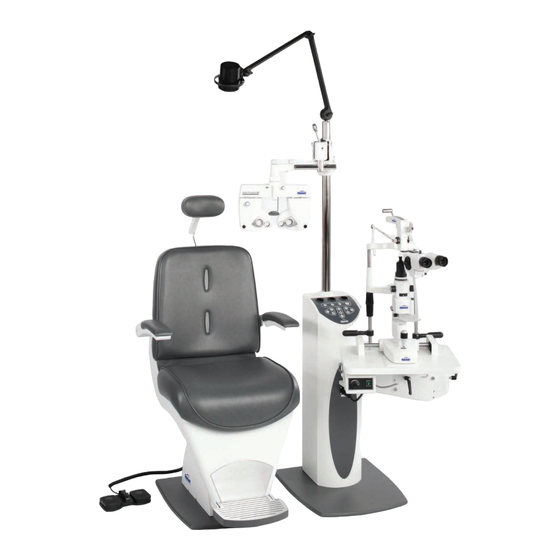
- Page 1 Endurance ™ Tilt Chair and Stand User’s Guide...
- Page 2 © 2012 Reichert, Inc. Reichert is a registered trademark of Reichert, Inc. All other trademarks are property of their respective owners. The information contained in this document was accurate at time of publication. Specifications are subject to change without notice. Reichert, Inc.
-
Page 3: Table Of Contents
Table of Contents Table of Contents ......................... 3 Warnings and Cautions ........................ 4 Symbols............................4 Introduction........................... 5 Unpacking ..........................5-10 Contents of Packaging ....................... 12 Features and Functions ......................11-13 Installation and Assembly ...................... 14-19 Lower Instrument Arm Assembly ..................14 Vertical Post Assembly ...................... -
Page 4: Warnings And Cautions
Warnings and Cautions WARNING: AN INSTRUCTION THAT DRAWS ATTENTION TO RISK OF INJURY OR DEATH. WARNING: DO NOT REMOVE OR DEFEAT THE EARTH GROUND CONNECTION ON THE ENDURANCE TILT CHAIR AND STAND POWER INPUT CONNECTOR OR THE UNIT’S POWER CORD. DAMAGE TO THE ENDURANCE TILT CHAIR AND STAND AND OR INJURY TO THE OPERATOR MAY OCCUR. -
Page 5: Introduction
Introduction Congratulations on the purchase of your new Endurance Tilt Chair and Stand. This User’s Guide is designed as a training and reference manual for operation, maintenance, and troubleshooting. We recommend that you read it carefully prior to use and follow the instructions in the guide to ensure optimum performance of your new products. - Page 6 Unpacking Unpacking the Endurance Tilt Chair 2. Remove the six screws (three each on opposite sides of the box) that secure the carton to the pallet. 3. Lift the carton off the chair. 4. Using a 14 mm wrench, remove the large screws on the board at the front of the chair.
- Page 7 Unpacking (continued) 5. Remove the remaining packing materials from the chair. Retain the box with additional parts for set-up. Carefully slide the chair off the pallet. Unpacking the Endurance Stand 1. Remove the plastic banding straps from the shipping carton. Endurance Tilt Chair and Stand User’s Guide 15250-101 REV-A...
- Page 8 Unpacking (continued) 2. Remove the six screws (three each on opposite sides of the box) that secure the carton to the pallet. 3. Lift the carton off the stand. 5. Cut the wire ties that secure the pole for the stand inside the box and remove it.
- Page 9 Unpacking (continued) 6. The plastic covering on the stand is secured with staples.Carefully pull away the plastic wrap. 7. The stand is packed with the lower arm mounted and two boxes of parts. 8. Remove the boards that secure the base of the stand to the pallet.
- Page 10 Unpacking (continued) 9. Using a 14 mm wrench remove the large screws that secure the board at the front of the pallet. 10. Remove the plastic wrap from the stand and boxes. 11. Remove the boxes from the stand and carefully slide the stand off the pallet.
-
Page 11: Features And Functions
Features and Functions Contents The items listed below should be included in the Endurance Tilt Chair and Stand packaging containers. If any of these items are missing, please contact Reichert Customer Service. • Advantage Plus Chair (P/N 15250) • Foot Switch Assembly (P/N 15250-002-001) •... -
Page 12: Contents Of Packaging
Features and Functions Contents of Stand Accessory Boxes Box 1 A. Overhead Lamp Assembly B. Power Cord for Stand C. Lamp Cord D. Slit Lamp Arm Wrench E. Collar for Base of Pole F. Armlock Screw Handle G. Phoropter Safety Collar H. - Page 13 Features and Functions (continued) Control Panel Chart Projector Hand Instrument ON/OFF Switch & LED Charging Wells Lower Arm (Slit Lamp) ON/OFF Switch & LED Charge Indicators ON/OFF Button for Power to Membrane Panel Voltage Selector Switches & Scale: Accessory ON/OFF switch Controls voltage to corded instrument binding posts on...
-
Page 14: Installation And Assembly
Installation And Assembly WARNING: TO REDUCE THE RISK OF ELECTRICAL SHOCK, DO NOT CONNECT THE UNIT TO A POWER SOURCE UNTIL THE ASSEMBLY PROCESS IS COMPLETED. Before you begin the assembly process: 1. Be sure the floor is level. 2. Be sure your stand is correctly positioned in the desired location. Lower Instrument Arm 1. -
Page 15: Vertical Post Assembly
Installation And Assembly (continued) 3. Place the needle bearing assembly on top of the arm port before installing the slit lamp. G. Slit lamp leveling set screws H. Ø ¾ needle bearing assembly 4. Using the 5/32 allen key, adjust the instrument leveling set screws as needed to level the table when installing the slit lamp. -
Page 16: Optional Third Arm Installation
Installation And Assembly (continued) 3. Slide the white rod collar down to the base of the pole and tighten the allen key to hold it in place. C. Rod collar and key Optional Third Arm Installation 1. Slide the safety collar down the pole to the desired position for the Third Arm and tighten the allen key to secure it in place. -
Page 17: Overhead Lamp Assembly
Installation And Assembly (continued) Overhead Lamp Assembly 1. Feed the lamp cord through the mounting pole. Fit the rod cap with lamp wire extended into the top of the pole. 2. Connect the lamp cord to the keyed plug in the stand A. -
Page 18: Lower Instrument Arm
Installation And Assembly (continued) Counterbalancing of Lower Instrument Arm WARNING: THE LOWER INSTRUMENT ARM CAN RISE ABRUPTLY IF THE LOCK RELEASE LEVER IS PRESSED WHEN THE ARM IS IN THE DOWN POSITION AND IS NOT BALANCED. DO NOT LEAVE THE ARM IN THE DOWN POSITION WITHOUT AN INSTRUMENT INSTALLED ON THE ARM OR ACCIDENTAL MOVEMENT OF THE ARM MAY OCCUR, POTENTIALLY CAUSING INJURY. -
Page 19: Chair And Stand Set-Up
Installation And Assembly (continued) Chair Set-Up 1. Connect the power cords to the stand and the chair and plug them into outlets. 2. Connect the Chair Power/Control Cord to the stand and the chair. 3. Connector the Foot Switch to the connector on the chair base. Operation Lower Instrument Arm There are three locking handles on the lower instrument arm: one that controls the position of the lower section... -
Page 20: Control Panel
Operation (continued) Control Panel The Control Panel (See page 15 for Control Panel diagram) contains all of the electrical controls except (1) the Main Power ON/OFF Switch, (2) a secondary Chair UP/DOWN Switch and (3) the Lower Arm Vertical Motion Switch. Main ON/OFF Switch Located on the bottom left corner of the back of the stand the Main ON/OFF Switch controls the electric power for the entire stand. -
Page 21: Overhead Lamp On/Off Intensity Controls
Operation (continued) Overhead Lamp ON/OFF Brightness Controls The area labeled “LAMP” has 3 separate buttons and a minimum to maximum LED scale. Pressing the Up or Down Arrow one position at a time will increase or decrease lamp intensity. Pressing the POWER Switch will apply power to the Overhead Lamp. - Page 22 Operation (continued) Chair Operation (continued) Main ON/OFF Switch Located on the bottom right corner of the back of the chair the Main ON/OFF Switch controls the electric power for the chair. This switch is a rocker type. Press the side with the straight line “I”...
-
Page 23: Maintenance
Maintenance There is no periodic or routine maintenance required. Cleaning WARNING: BEFORE CLEANING WITH A DAMP CLOTH, DISCONNECT OR UNPLUG THE STAND FROM ANY POWER SOURCE. CAUTION: DO NOT USE SOLVENTS OR STRONG CLEANING SOLUTIONS ON ANY PART OF THE ADVANTAGE PLUS CHAIR &... -
Page 24: Specifications
Specifications Chair Stand Shipping Weight: 305 lbs 275 lbs (includes slit lamp & phoropter arm) Gross Weight: 270 lbs 240 lbs (includes slit lamp & phoropter arm) Baseplate: 20” wide by 22” deep 20” wide by 22” deep Input Voltage: 120 VAC, 60Hz 120 VAC, 60Hz Fuses:... -
Page 25: Warranty
Warranty This product is warranted by Reichert, Inc. against defective material and workmanship under normal use for a period of two years from the date of invoice to the original purchaser. The linear actuator lift mechanism is warranted for five years against defective material and workmanship under normal use. (An authorized dealer shall not be considered an original purchaser.) Under this warranty, Reichert’s sole obligation is to repair or replace the defective part or product at Reichert’s discretion.
Need help?
Do you have a question about the Reichert Endurance Tilt Chair and Stand and is the answer not in the manual?
Questions and answers