Table of Contents
Advertisement
Quick Links
Advertisement
Table of Contents

Related Manuals for Saluki S2106 Series


Summary of Contents for Saluki S2106 Series
- Page 2 PREFACE Thank you very much for buying and using Saluki S2106X series of Optical Time Domain Reflectometers (OTDR). This manual mainly contains the commonly used operating safety instructions, basic operation and specifications, as well as common troubleshooting guidelines and other information. In order to facilitate your use, before operating this instrument, please read the contents of this manual carefully and follow the instructions in the book correctly.
-
Page 3: Table Of Contents
CATALOG 1. Summary................................1 1.1 Unpacking inspection..........................1 1.2 Product Overview...........................1 1.3 Safety tips..............................2 1.4 Instrument Maintenance........................4 2. Basic Knowledge of OTDR..........................5 3. Basic operation and usage of OTDR series....................10 3.1 Front panel, top panel and bottom panel..................10 3.2 ON/OFF.............................. - Page 4 3.8 Visual Fault Location(VFL)........................ 29 3.9 Event Map.............................30 3.10 End Face Detector(FED)........................32 3.11 Loss Test (LT)............................33 3.12 System Information..........................34 3.13 Analysis Software..........................38 4. Common problems and Solutions.........................40 4.1 How to observe the optical pulse waveform?..................40 4.2 How to clean the optical output interface of OTDR?...............46 4.3 How to copy the internal documents of the instrument to the U disk or computer?....47 4.4 How to print test trace in batch?......................
-
Page 5: Summary
1. Summary 1.1 Unpacking inspection This instrument is packaged and transported strictly in accordance with GB/T 9174-2008 <General Technical Conditions for Freight Transport Packaging>. When you receive this instrument, please carefully check the product according to the packing list and check the appearance quality of the product, and timely find out the possible damage caused by the product in the process of freight transportation. -
Page 6: Safety Tips
or follow-up rapid and efficient maintenance and troubleshooting testing, this product can provide you with the highest performance solutions. 1.3 Safety tips External power supply The power adapter input meets the following requirements:100V~240V,50/60Hz;@0.5A。 The power adapter output meets the following requirements:12V~19V,1.5A,Polarity:center positive. Please use AC adapter attached to this instrument and use external power supply strictly in accordance with the specifications;... - Page 7 not used for a long time, please charge the battery regularly. It is recommended that the battery be charged every 2 to 3 months to ensure the best performance of the battery. Do not let the battery close to the source of fire or strong heat; do not open or damage the battery; take out the battery when the instrument is stored for a long time.
-
Page 8: Instrument Maintenance
can be cleaned by wiping with soft fabric. Tip: Do not press the LCD screen with sharp objects or wipe the LCD screen with organic solvents, otherwise the LCD screen may be damaged. In the process of using the instrument, without permission, users are strictly forbidden to dismantle the machine without permission, otherwise they will lose the warranty qualification! Except for 1625nm/1650nm wave, other waves can not be tested with light (on-line test). -
Page 9: Basic Knowledge Of Otdr
2. Basic Knowledge of OTDR OTDR is a precise optical fiber measuring instrument based on the principle of Rayleigh scattering and backscattering generated by Fresnel reflection when laser propagates in optical fibers. By measuring the transmission time of optical pulses from one to the other, the distance L is calculated using the formula L=c×t/(2n), L unit is m, C is the propagation speed of light in vacuum 2.99792 ×10 m/s, t is the time of light pulse from emission to return (unit is s), n is the group refractive index, designated by the optical fiber... - Page 10 refractive index difference and the smoothness of the boundary surface. The event of OTDR test refers to the abnormal point that causes abrupt change of loss or reflection power. Including all kinds of connection points, fusion points and bending, cracks or breaks in optical fiber links, which lead to the loss of transmission signals.
- Page 11 (2) Non-reflective event When OTDR pulses propagate along the measured optical fibers, such as where there is a partial loss of energy due to fusion or bending, there is no abrupt change in refractive index, so the reflection phenomenon will not occur or can be ignored.
- Page 12 distance that OTDR can test under the condition of the maximum test pulse width provided by the instrument. Therefore, under the same link condition, the larger the dynamic range, the longer the distance of the optical fiber link that the instrument can test. The maximum test distance of OTDR is different, because the loss of the link under test is different.
- Page 13 (5) Splice Loss This series of OTDR mainly use four-point marking method: Measurements are performed at four points: starting point A, starting point B, ending point C and ending point D. The weld loss is calculated by the level difference of the mark B of the approximate line between B-A and C-D.
-
Page 14: Basic Operation And Usage Of Otdr Series
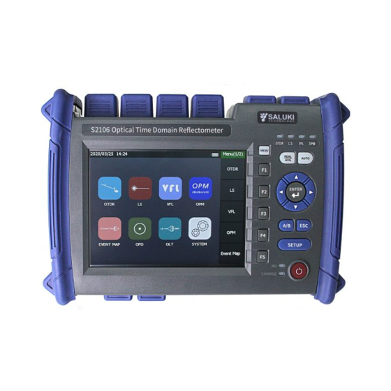
3. Basic operation and usage of OTDR series 3.1 Front panel, top panel and bottom panel... -
Page 15: On/Off
3.2 ON/OFF Press the power switch for more than 3 seconds. If the instrument starts normally, ON indicator lights up and displays the main screen. If an external adapter is connected and the battery is charged, the CHARGE LED is red. When the battery is full, the CHARGE LED is green. -
Page 16: Main Menu
Attention: Before connecting the cable connector, make sure that the type of connector is matched. The wrong type of joint or contaminated joint will not only lead to inaccurate measurement, but also may damage the optical interface of the instrument. The correct way: clean the end face with absolute alcohol before inserting the optical fiber connector (jumper), and then connect with the instrument after the alcohol evaporates. -
Page 17: Otdr Operation
3.5 OTDR Operation OTDR interface, after the test , the event list is displayed, shows distance, slope, event loss, reflection and total loss of cable starting point, cable section, intermediate event point and end. - Page 18 3.5.1 Introduction and Setting Method of Parameters necessary accurate measurement to set parameters instrument correctly. Therefore, before using the instrument, the parameters must be set according to the requirements. Press [SET] or "Advance" menu to enter the parameter setting interface, press the corresponding menu, you can check the corresponding functions.
- Page 19 Wave:Set the test wavelength of OTDR。 Setting method: Under the parameter setting interface, the corresponding wave can be selected by pressing [Wave], [1310nm], [1550nm] or [1310/1550nm]. Measurement mode:The method used to select OTDR scanning events includes "auto test", "real test" , "average test"...
- Page 20 Test Range:Setting scanning track range. Range setting is based on the actual length of the optical fiber to select the corresponding predefined range, must be greater than the length of the measured optical fiber, usually required to be set to about twice the length of the measured optical fiber.
- Page 21 Index of refractive (Ior): The refractive index of the fiber affects the transmission speed of the laser in the optical fiber, so whether its value is set accurately or not directly affects the distance accuracy of the measurement. It is provided by optical fiber manufacturers, which range from 1.0 to 2.0, and the default value is 1.468.
- Page 22 Receiving fiber length: used to set the length of OTDR terminal access guide fiber, ranging from 0 to 100. The unit is consistent according to the set unit, which is usually 0 by default. Setting method: press [receive fiber length] to pop up the input interface, and then [OK] to exit.
- Page 23 Return loss threshold: Used to set the loss threshold of link reflection events that OTDR can test, ranging from 10 to 60, usually defaulting to 40. Setting method: Under the parameter setting interface, press the [Return Loss], pop up input interface, input the threshold value, press [OK] to exit.
- Page 24 Note: Refractive index, cable correction, event loss threshold, reflection loss threshold and end loss threshold need not be changed. If the default value needs to be restored after the change, in the parameter setting interface, press [Restore]. 3.5.2 Start test Automatic test: set up [Wave], after confirmation, press [Auto Test] and directly press the "Auto"...
- Page 25 Event type: the event type of the current event point; : Starting point, which indicates the starting position of the fiber link. (1) : Falling event, indicates that this event point is a non-reflective event point in the middle of the (2)...
- Page 26 The parameters in the event list are explained in detail: Distance(km):Distance for the current event point; Slope(dB/km):Average loss of distance in linear zone; Loss(dB): Current event point loss in optical fiber links; Return Loss(dB):Return Loss at current event point; Total Loss(dB):The total loss of the link between the starting point and the current event point in the link. 3.5.4 Trace Operation 3.5.4.1 Moving and Switching cursors Press...
- Page 27 the current active cursor position as the center; press to realize the horizontal enlargement and 、 reduction function of the test curve with the current active cursor position as the center; press to restore the original scale display of the trace. 3.5.5 File Operation 3.5.5.1 File Save The OTDR test track storage format of this series is based on the SR-4731 standard clause of Bell...
- Page 28 Cable ID and Cable Code set at the initial laying of line. Data Flag: BC - Create a test for newly laid optical fiber lines; RC - Maintenance is the completion of line laying and later maintenance testing; OT - Others are tested according to the actual situation. O.Location: Link Starting...
- Page 29 seconds on September 9, 2019, whose name is 201909080859.SOR. Fast Save - By Name: Name the trace by the last name + 1. For example, the name of the previous track storage is "Qingdao-Jinan 1", and the name of this storage is "Qingdao-Jinan 2", followed by + 1. Auto Save - By Auto Test: Name the automatic test trace according to the end time of the test or the last name + 1.
- Page 30 3.5.5.4 File Copy Under the main interface of OTDR, press [File] - [File Copy] to enter the file copy interface. From memory to U disk: Double-click the file name in the memory file or press [Select] to select the file you want to copy, press the copy menu or copy the file in memory to the U disk.
-
Page 31: Optical Power Peter(Opm
3.6 Optical Power Peter(OPM) main menu interface, press the icon to enter the OPM function. measured light signal connected optical interface through optical fiber jumper, test wavelength is selected to start power measurement. Absolute power, relative power and linear power are converted as follows: =10lgP /1mW,... -
Page 32: Laser Source (Ls)
3.7 Laser Source (LS) main menu interface, press the icon to enter LS function. output light interface and wavelength of the light source function are consistent with OTDR. Press the "OFF" below the corresponding wavelength in the right wavelength menu or status information to open the source of the corresponding wavelength, and then press the "ON"... -
Page 33: Visual Fault Location(Vfl)
3.8 Visual Fault Location(VFL) In the main menu interface, press the icon to enter the VFL function. Press [Normal] to turn on the red light and output the continuous light; press [1Hz] or [2Hz], the red light outputs the modulated light at 1Hz or 2Hz frequencies. -
Page 34: Event Map
3.9 Event Map In the main menu interface, press icon to enter the event map interface. Press the upper left corner to select the wave and select [Auto test] to start the test. Press [File] to open existing curve interface, and press [save] to save the curve of current test link. - Page 35 Press the [Threshold] to enter the setting interface: Splice Loss: Click on "+" and "-" can increase or decrease the threshold, each step changes 0.02dB, or click the corresponding position of the threshold. Connection Loss: Clicking on "+" and "-" can increase or decrease the threshold, changing 0.25dB per step, or clicking on the corresponding position of the threshold.
-
Page 36: End Face Detector(Fed)
Press the "Switch Trace Display" menu in the lower right corner of the screen, and the whole measured optical fiber link is displayed graphically. The event type of each event point, the distance from the instrument test port, the result of "Pass/Fail" judgment and the distance between two adjacent events are displayed in the event map. -
Page 37: Loss Test (Lt)
3.11 Loss Test (LT) In the main menu interface, press the icon to enter the optical loss test interface. The steps are as follows: 1) Connect LS and with standard jumper, press [Start], after power is stable, press[OPM Reference]; 2) The standard jumper is used to connect the DUT to LS and OPM, and the insertion loss of... -
Page 38: System Information
3.12 System Information In the main menu , press the icon to enter the system information interface. Device information: contains host number and module . Use wave: the wave that the host can output. Version Information: the version information of the whole instrument software system software. - Page 39 3.12.1 System Settings system information interface, press the [Sys-Set] menu to enter the system settings. Date Time: Click the arrow icons on both sides of year, month, day, hour, minute and second, to adjustment, and then confirm. Language: Chinese or English display is optional.
- Page 40 3.12.2 System Help system information interface, press the [Help File]. Help information includes OTDR test process, test notes, optical power meter, detection other functions. Click on the corresponding entry view relevant content. Click the left and right arrows to switch items.
- Page 41 3.12.3 Touch Calibration system information interface, press [T-Adjust] calibrate the touch screen. 3.12.4 Software Update Insert the U disk with the update software (create a folder named "OTDR" in the U disk root directory, and put the upgrade file FTX-1000.exe in the "OTDR" folder) into the instrument.
-
Page 42: Analysis Software
3.13 Analysis Software analyse_Otdr software is equipped in the U disk of the instrument. Copy it to computer. Double-click Open, click [File] - [Open] select Trace Storage Directory to view all files in the directory. - Page 43 3.13.1 Trace Analysis Open the selected file, analyze and operate the trace through the trace operation menu, and the event information is displayed in the event list. 3.13.2 Report Print Click on File - [BatPrint] to select Trace Storage Directory to view all the files in the directory.
-
Page 44: Common Problems And Solutions
4. Common problems and Solutions 4.1 How to observe the optical pulse waveform? Pulsed light emitted by OTDR injects into different locations of the measured optical fiber links, which can cause loss, such as connection points, bends and end of the optical fiber. - Page 45 Near-end reflection: Reflection occurring at the junction between OTDR and the connector of the optical cable. This also includes the internal reflection of the instrument, and the loss and reflection between the connecting points cannot be detected in the near-end reflective area. Splice loss: Due to the uneven density of the welded parts or the change of material quality, the increase of Rayleigh scattering loss results in the welding loss.
- Page 46 4.1.1 Normal Curve As shown, how to judge whether the curve is normal or not? (1) The main slope of the curve is basically the same, and the slope is smaller, which indicates that the attenuation constant of the line is higher than that of the line.
- Page 47 4.1.3 High Slope of Curve As in the upper right figure, the slope of this section is obviously larger, which indicates that the quality of this section of optical fiber is not good and the loss is large. 4.1.4 No reflection peak at the far end of the curve As shown in the lower right figure, there is no reflection peak at the tail of the curve, which indicates that the quality of the distal end of the optical fiber is not good or that the distal end of the optical fiber is...
- Page 48 4.1.5 Positive Gain Phenomenon Processing Positive gain may occur on the OTDR curve, as shown in the right figure. Positive gain is due to more backward astigmatism produced by the fibers after the fusion point than those before the fusion point. In fact, the optical fibers have a loss at this fusion point.
- Page 49 4.1.6 Recognition and Processing of Mirage Peak (Ghost) Recognition of phantom peaks (ghosts): The ghosts on the curve do not cause obvious loss (such as the upper right figure); the distance between the ghosts and the beginning of the curve is a multiple of the distance between the strong reflection event and the beginning, which is symmetrical (such as the lower right figure).
-
Page 50: How To Clean The Optical Output Interface Of Otdr
4.2 How to clean the optical output interface of OTDR? The optical output interface of OTDR is a replaceable interface, which must be kept clean. When the instrument is unable to test the normal curve or the test results are inaccurate, the first consideration is to clean the optical interface of the instrument. -
Page 51: How To Copy The Internal Documents Of The Instrument To The U Disk Or Computer
4.3 How to copy the internal documents of the instrument to the U disk or computer? Copy to the U disk: insert the U disk into the top USB port of the instrument, enter the main interface of OTDR, press [File]- [Copy], enter the copy interface. Double-click on the file that needs to be copied in the selected memory file, press the Copy menu or copy the file to the U disk. -
Page 52: Other Common Faults And Treatment Methods
4.6 Other common faults and treatment methods Fault Description Causes Solution Charge the battery and observe the switch key Cannot be started normally. The battery has run down. lamp. If the red light is displayed, continue charging. Otherwise, contact the supplier. The use environment does not meet the Charging environment is 0℃~50℃. - Page 53 phenomenon at the front of Clean the instrument with clean cotton chips Fiber coupling is not good. test curve. and the measured optical fiber end face. The output surface of fiber is polluted. Replacement of output connector. The reflection peak at the beginning decreases slowly The output connector is damaged.
-
Page 54: Technical Specifications
5. Technical Specifications S2106X OTDR Model Type SM/MM 1310nm 850nm 1310nm 1310nm /1490nm 850nm/ /1300nm Wavelength 1310/1550nm /1490nm /1550nm /1550nm 1300nm /1310nm /1550nm /1625nm /1625nm /1550nm 35/33dB 38/36dB 42/40dB 45/43dB 37/35/35dB 37/35/35dB 37/35/35/35dB 28/26dB 28/26/35/33dB Dynamic Range ① Event Blind Zone 0.8m 0.8m 0.8m... - Page 55 Ranging accuracy ±(0.75m+ Sample interval +0.005%×Test distance) Loss accuracy ±0.05dB/dB Sample Points 16k~256k Sample Resolution 0.05m~16m Reflection ±3dB Accuracy File Format SOR Standard File Format Loss Analysis 4-point method /5-point method Laser Safety Level Class Ⅱ Refresh Rate 3Hz (Typ.) Data Storage Internal storage:8G,External storage:4G Output Interface...
- Page 56 S2106P PON OTDR Model 1310nm±20nm 1625nm±20nm 1650nm±15nm 1310nm/1550nm±20nm 1310nm/1550nm±20nm Wavelength 1550nm±20nm (Filtered) (Filtered) 1625nm±15nm(Filtered) 1650nm±15nm(Filtered) Band pass Band pass High Pass>1595nm, High Pass>1595nm, 1650nm±7nm, 1650nm±7nm, Filter Isolation>50dB Isolation>50dB Isolation>50dB Isolation>50dB (1270nm~1585nm) (1270nm~1585nm) (1650nm±10nm) (1650nm±10nm) Fiber type G.652 37/35dB 38dB 38dB 38/35/35dB 38/35/35dB Dynamic Range...
- Page 57 Loss Resolution ±0.001dB Loss Accuracy ±0.05dB/dB Sample Points 16k~256k Sample Resolution 0.05m~16m Reflection ±3dB Accuracy File Format SOR Standard File Format Loss Measurement 4-point method /5-point method Mode Laser Safety Level Class Ⅱ Refresh Rate 3Hz (Typ.) Data Storage Internal storage:100M(≤3000 curves) ;External storage:4G bit Connector FC/UPC(Interchangeable SC、ST)...
- Page 58 Wavelength range 800nm~1700nm Connector Universal FC/SC/ST Test scope -50dBm~+26dBm Uncertainty ±5% 850nm/980nm/1300nm/1310nm/1490nm/1550nm/1625nm/1650nm Calibration wavelength Wavelength Consistent with OTDR output wavelength Laser Type FP-LD Connector FC/UPC(Interchangeable SC、ST) Output power ≥-5dBm Stability CW,±0.5dB/15min(Test after 15 minutes of boot-up preheating) Wavelength 650nm±20nm Output power ≥5mW (Customized ≥10mW)
- Page 59 Mode CW/1Hz/2Hz Connector FC/UPC(Interchangeable SC、ST) The Optical Loss Test index refers to the above light source and optical power meter index. Others Display 7 inch color LCD + touch screen AC/DC adapter:Input:100V~240V,50/60Hz,0.6A;Output:12V~19V,1.5A Power supply Lithium battery:7.4V,5200mAh Working temperature -10℃~+50℃ Storage temperature -40℃~+70℃...
- Page 60 Configuration List Name Quantity Host AC/DC adapter Note: OTDR interface type U-disk (including analysis software, instructions) designated FC/UPC, and FC/APC type Touch pen is optional. Data line Note: Due to the need of design OTDR SC adapter improvement, the above contents are OPM SC adapter subject to change without notice.