Table of Contents
Advertisement
Quick Links
Thank you very much for purchasing and using this series of optical time domain reflectometers.
This manual mainly contains the common operation and maintenance information of the instru-
ment, as well as the common troubleshooting guide and other information. In order to facilitate
your use, please read the contents of this manual carefully before operating the instrument, and
follow the instructions of this manual correctly.
This manual is only used with this instrument. Any company or person is allowed to tamper, copy
and disseminate the contents of this manual for commercial purposes without the authorization
of the company.
The contents of this manual are subject to change without notice. If you have any questions,
please call the supplier, we will provide you with the best service!
Due to the need of design improvement, the contents are subject to change without notice.
Summary
This series of OTDR is a multi-functional optical measuring instrument, which integrates auto OTDR,
expert OTDR, event map, optical power meter, visual fault location, power adjustable stable light
source, end face detection, optical loss test, cable line length / sequence test, cable tracking and
other functions. It has touch screen and heys. It is the right assistant for optical cable construction,
installa-tion and maintenance, project acceptance and on-site repair.
Warning
When using the instrument, do not look directly at the laser output port or the end of the optical fiber
with your eyes, avoid eye damage! Except for 1625nm/1650nm, all the others are off-line test wave-
lengths, which will cause damage to internal components of the instrument if forced to use! Any
change or modification not explicitly permitted in this manual will deprive you of the right to operate
the equipment. To reduce the risk of fire or electric shock, do not expose the equipment to thunder-
storm or humid environment. In order to prevent electric shock, please do not open the shell. It must
be repaired by qualified personnel designated by the manufacturer
Attentions
Battery: the battery is a special polymer lithium battery, the charging voltage is 5V/2A, and the
charging temperature range is 0 ℃~ 50 ℃. When the ambient temperature is too high, the charging
will automatically terminate. The battery should be charged every one month to avoid long storage
time and failure of battery due to self discharge. The temperature range of battery during long-term
storage is: - 40 ℃ ~ 50 ℃.
Please use the special adapter attached with the instrument box and use the external power supply
in strict accordance with the specifications, otherwise the equipment may be damaged.
End Face Cleaning: Before testing, clean the end face of the tested fiber joint with alcohol cotton.
LCD screen: the display of this series of instruments is 4.3 inch color LCD. In order to maintain good
viewing effect, please keep the LCD screen clean. When cleaning, wipe the LCD screen with soft fabric.
OTDR&LS
OPM
VFL
Enter the main menu after power on, there are 12
function modules. Press the direction key to select the
module, and then press the "OK" key or directly press
the function icon to enter the corresponding function
interface.
Date &Time
2020-10-20 09:25
Press the "Shortcut menu" icon to enter the quick
operation menu, and press different function icons to
enter the corresponding function interface or realize the
corresponding operation function.
Print Screen: Capture the current interface, the picture
is automatically saved in the instrument, and the file
name is the time when the screenshot is generated.
OTDR is an optoelectronic integrated instrument made
of Rayleigh scattering and Fresnel reflection when
optical signal is transmitted in optical fiber. It is widely
used in the maintenance, construction and monitoring
of optical cable lines. It can measure the length of
optical fiber, transmission attenuation of optical fiber,
attenuation of connector and fault location.
Auto OTDR: it only needs to set the wavelength and
measurement time, and other parameters are automat-
ically selected by the instrument to complete the test.
For the specific meaning and explanation of each
parameter, please refer to "expert OTDR".
Attention
Please do not make online test except online wavelengths!
Expert OTDR: parameters such as wavelength, test
range and pulse width shall be set.
The test results are more accurate by selecting the
appropriate measurement parameters in the expert
mode. You can zoom in on the curve to see the details of
each event.
The curve and event list are displayed
Curve
at once.
Link results are summarized to a list.
List
Switch to event icon display mode.
Event Map
Save current curve file quickly.
FastSave
Enter parameter setting interface.
FastSet
Wave: the emit wavelength, which can be measured at
1310nm or 1550nm.
Test range:range setting is based on the actual length
of the optical fiber to select the corresponding
predefined range, must be greater than the length of the
measured optical fiber, usually required to be set to
about twice the length of the measured optical fiber.
Auto test: OTDR automatically matches the most
suitable parameters for the current test, and the select-
ed values of test range and pulse width cannot be
modified.
Manual mode: set the value of measurement range and
pulse width manually.
Pulse width: refers to the time width of the optical
pulse signal emitted during test. The larger the pulse
width, the stronger the optical power injected into the
optical fiber, the stronger the backscattering signal of
the optical fiber is, and the farther the effective detec-
tion distance of the OTDR can be. However, the large
pulse width will cause saturation of the initial reflection
signal and a large blind area. The choice of pulse width
is related to the length of the optical fiber. The longer
the length, the larger the pulse width, which can only be
modified in real-time/average measurement mode.
Threshold settings
Event loss threshold: set the loss threshold of connec-
tion point, fusion point or macro bend in the link that
can be tested, between 0.2~30dB, and the default value
is 0.2dB. Events larger than the set threshold will be
listed in the event table, or those will be ignored.
Reflection threshold: set the return loss threshold of
the link reflection events that can be tested, ranging
from 10dB to 60dB, and 40dB by default.
End threshold: set end loss at the end of the link that
can be tested, ranging from 1~30dB, 10dB by default.
Eligibility criteria
Set the judgment value for the average loss of connec-
tion/fusion/bending/link. If it is less than the value, it is
judged as "PASS", otherwise it is "FAIL".
Connection loss: reflection event, refers to flange, SC,
LC and other joints;
Welding loss: non reflective event, refers to fusion;
Bending loss: non reflective events caused by fiber
bending, need to be tested at two wavelengths at once;
Average loss: the loss value per kilometer of the link
under test.
Select correct parameter, the test results such as curve
and event list will be displayed after test completed.
Curve zoom
Press the [zoom] menu to enter the zoom in and zoom
out mode.
/
Zoom in or out in X direction
/
Zoom in or out in Y direction
Press [1:1] to return to the original scale display
Event list
List: the tested results are displayed in the form of a list.
Total length: the total length of the link under test.
Total loss: the total loss of the link under test.
Slope: the loss per kilometer of the link under test.
Total events: the total number of events, the number of
passed events and the number of failed events of the
link under test.
In the event list:
NO.: the order of the current event.
Type: the type of the current event.
Distance: the location of the current event.
After the measurement, press [save] to save the file,
enter the file name, and press [enter] to save the file.
You can also press [Fastsave] to save the file. The file is
saved in a folder named the same day' s date.
Auto save: open the auto save function, the file name
will be automatically generated according to the rules;
File naming method (only valid for "auto save" and
"one click save"):
①+④: file name + fiber number naming, fiber number
increasing in order;
①+②+④: file name + wavelength + fiber number
naming, fiber number increasing in order;
①+②+③+④: file name + wavelength + pulse width +
fiber number, and the fiber number increases in order.
File name: enter the file name manually;
Optical fiber code ID: the optical fiber number and
code set when the line is initially laid;
File operation
All the test curves are saved in the standard SD
card of the instrument. Press [File] to enter the
file operation interface. You can open, delete and
rename files.
PREFACE
⑤
⑥
⑦
⑧
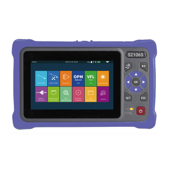
S2106S
SET
ESC
ON
CHARGE
⑤
ON
CHARGE
Function keys
Main interface
Flashlight
Battery
TF card
Shortcut menu
Expert OTDR
Parameter setting
Threshold/Criterion
OTDR-File save
File Operation
Host
Top
OTDR/LS port
OPM port
VFL port
Flashlight
RJ45 Cable Tracker port
⑤
Rj45 Sequence/Length port
⑥
TF card
⑦
Type C USB
⑧
S2106S
SET
ESC
ON
CHARGE
Power ON/OFF key
press less than 2s to turn on the machine, pr.ess more than
2s to pop up the shutdown confirmation pop-up window;
When power on, short press to turn on or off the flashlight.
Home
Auto OTDR
Expert OTDR
Optical
RJ45 Sequence
Loss Test
RJ45 Length
AUTO
Auto test
File
Auto OTDR
/dB
Auto test 1550nm 100km 10000ns
32.0
28.0
24.0
20.0
16.0
12.0
8.0
4.0
0.0
10
20
1310nm
Curve
List
/dB
Auto test 1550nm 100km 10000ns
32.0
28.0
24.0
20.0
16.0
12.0
8.0
4.0
0.0
10
20
1550nm
100km
Curve
List
Attention
Please do not make online test except online wavelengths!
Test settings
Wave
Range
Pluse Width
Avg. Time
Refractive Index
Unit
Transmitting cable
End cable
IOR: provided by optical cable or fiber manufacturer.It is
the key parameter for calculating the distance, and can
not be set arbitrarily.
Test time: it is used in the average test mode. The longer
the test time is, the better the signal-to-noise ratio of the
signal is improved, and the more accurate the test result is.
The user should choose the test time reasonably. It is
proportional to the dynamic.
Unit: select the required unit, there are three options for
km/kfeet/miles.
Test Settings
Loss Threshold
Reflectance Threshold
End of Fiber Threshold
Backscatter Coefficient
Test Settings
Pass Criterion
OTDR-Curve
/dB
/dB
平均 1550nm 100km 10000ns
Auto test 1550nm 100km 10000ns
32.0
32.0
28.0
28.0
24.0
24.0
20.0
20.0
16.0
16.0
12.0
12.0
8.0
8.0
4.0
4.0
Section(km)
0.0
0.0
10
10
20
20
NO. Type Distance km
Section km
1
37.56813
2
71.25212
Curve
List
Segment: the distance between the previous event and
the current event.
Loss: the loss of the current event.
Total loss: the loss from the starting point to the current
event.
Slope: the loss per kilometer from the starting point to
the current event.
Reflection: the return loss of the current event.
Save
Naming Type
File name
Autosave
Fiber ID
Location A
Location B
Direction
Operator
Location A: Link start point location
Location B: Link termination point location
Direction: Optical fiber test direction, from A to B,
from B to A;
Operator: enter the name of the tester.
File Operation
Device Catalog
Storage Card
20200421
20200521
20200702
20200929
Main view
Dust cover
4.3 inch color LCD
Function keys
Charging indicator
Power on status indicator
⑤
Bottom
RJ45 Sequence test remote
Zoom control / AB cursor switch key
According to the OTDR waveform, combine
with the direction key operation; In the
switch curve scaling, A/B cursor movement
function.
Test / Stop key
OTDR: press to start or stop test
Direction key up, down, left and right
ESC key exit current function
SET key enter the OTDR parameter
setting interface
2020-10-20 09:25
dB/dBm/mW
Event Map
OPM
RJ45
End Face
Digital Tracker
Inspector
Management
Menu
VFL
Home
Print Screen
Power Off
30
40
50
60
70
80
5s
Event Map
FastSave
37.56813m 19.256dB
A
71.25212m 10.251dB
B
30
40
50
60
70
Real Test
10000ns
Avg. Test
5s
Event Map
FastSave
2020-10-20 09:25
1310nm
Wave
1310nm
64km
1550nm
10000ns
5s
km
0km
0km
2020-10-20 09:25
Auto
Event Loss Thre.
Auto
Auto
Customize
Auto
2020-10-20 09:25
Pass Criterion
Connection Loss
Splicing Loss
Bending Loss
Link Loss
Average Loss
1550nm
1310nm
37.56813m 19.256dB
37.56813m 19.256dB
A
A
71.25212m 10.251dB
71.25212m 10.251dB
B
B
30
30
40
40
50
50
60
60
70
70
Loss dB
Total-L dB
Avg.L dB/km Return dB
0.00000
8.176
0.195
0.85
33.68399
15.418
0.215
--
Event Map
FastSave
2020-10-20 09:25
File naming
① + ④
otdr
① + ② + ④
Yes
① + ② + ③ + ④
① File name
② Wavelength
③ Pulse Width
④ Fiber ID
2020-10-20 09:25
File List
No.
File name
1
20200421-1318OTDR.bmp
2020-04-21 13:18
OTDR-1550-500ns-001.sor
2020-04-21 13:25
2
3
OTDR-1550-500ns-002.sor
2020-04-21 13:27
OTDR-1550-500ns-003.sor
2020-04-21 13:32
4
5
OTDR-1550-2000ns-001.sor
2020-04-21 14:42
6
OTDR-1550-2000ns-002.sor
2020-04-21 14:58
OTDR-1550-2000ns-003.sor
2020-04-21 15:26
7
8
OTDR-1550-5000ns-001.sor
2020-04-23 16:32
9
OTDR-1550-5000ns-002.sor
2020-04-23 16:45
OTDR-1550-5000ns-003.sor
2020-04-23 16:56
10
Page 1 / of 8
1.
1.
2.
3.
650nm
VFL
Laser Source
File
System
Flashlight
Exit
4.
Test
Settings
Zoom
Files
90
/km
Save
AutoTest
Exit
Settings
5.
1:1
Settings
Cursor A
Zoom
Files
80
90
/km
Save
AutoTest
Exit
FastSet
6.
Test
Settings
Pass
Criterion
Analysis
Threshold
Default
Exit
7.
Test
Settings
0.20dB
Pass
Criterion
Analysis
Threshold
Default
Exit
Test
0.20 dB
Settings
0.20dB
3.00
dB
Pass
Criterion
32.00
dB
Analysis
Threshold
0.25dB
Default
0.40dB
Exit
8.
1:1
1:1
Settings
CursorA
Zoom
Files
/km
80
80
90
90
/km
Save
40.22
43.26
Exit
FastSet
9.
Back
10.
76 Files
Select all
Date
Delete
Rename
Back
Advertisement
Table of Contents

Related Manuals for Saluki S2106S Series


Summary of Contents for Saluki S2106S Series
- Page 1 PREFACE Thank you very much for purchasing and using this series of optical time domain reflectometers. This manual mainly contains the common operation and maintenance information of the instru- ment, as well as the common troubleshooting guide and other information. In order to facilitate your use, please read the contents of this manual carefully before operating the instrument, and follow the instructions of this manual correctly.
- Page 2 Event Map The function is fully one key automatic test, and the Total events: 4 Total length Total-L Avg.L information such as the length of the optical fiber link to 0.197dB/km Pass: 3 Fail: 1 95.05625km 18.726dB Test be measured, the type of the joint and the position of 95.05625km the breakpoint are displayed graphically, and the 0 km...
Need help?
Do you have a question about the S2106S Series and is the answer not in the manual?
Questions and answers