Advertisement
Quick Links
Advertisement

Related Manuals for Saluki S3302E


Summary of Contents for Saluki S3302E
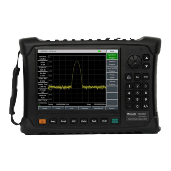
- Page 1 S3302 Series Spectrum Analyzer Maintenance Manual Saluki Technology Inc.
- Page 2 S3302B handheld spectrum analyzer (9kHz-26.5GHz). S3302C handheld spectrum analyzer (9kHz-32GHz). S3302D handheld spectrum analyzer (9kHz-44GHz). S3302E handheld spectrum analyzer (9kHz-50GHz). S3302F handheld spectrum analyzer (9kHz-67GHz). Standard pack and accessories: Item Main Machine Power cord...
- Page 3 Tel: 886.909 602 109 Email: sales@salukitec.com www.salukitec.com Model No. Description Note To Realize Modulation Characteristics Analysis of S3302-17 AM/FM/PM analyzer option AM/FM/PM Signals. To Realize Signal Power Measurement of Multiple S3302-18 Channel scanner option Channels and Frequency. To Realize Continuous Sweep Measurement of S3302-19 List sweep option Various Frequency Bands .
- Page 4 Tel: 886.909 602 109 Email: sales@salukitec.com www.salukitec.com Model No. Description Note 6GHz omnidirectional antenna (680MHz S3302-51 Portable omnidirectional antenna - 6GHz) 8GHz omnidirectional antenna (300MHz S3302-52 Portable omnidirectional antenna - 8GHz) S3302-53 VHF/UHF portable antenna Frequency range :140MHz/430MHz Passive directional antenna S3302-54 Passive log-periodic antenna (700MHz - 4GHz)
- Page 5 Manual rests with Saluki. Saluki Tech owns the copyright of this document which should not be modified or tampered by any organization or individual, or reproduced or transmitted for the purpose of making profit without its prior permission, otherwise Saluki will reserve the right to investigate and affix legal liability of infringement.
-
Page 6: Table Of Contents
Tel: 886.909 602 109 Email: sales@salukitec.com www.salukitec.com CONTENTS Chapter 1 Product Overview..........................6 Chapter 2 Working Principle..........................7 Chapter 3 Analysis on Common Faults......................9 Chapter 4 Repair of Parts..........................12 Chapter 5 Calibration of the Main Unit......................17... -
Page 7: Chapter 1 Product Overview
Tel: 886.909 602 109 Email: sales@salukitec.com www.salukitec.com Chapter 1 Product Overview The S3302 series spectrum analyzer embraces such advantages as wide working frequency band, high performance indexes, high sweep speed, multiple test functions and easy operation. The integration of 8.4 inch LCD and capacitive touch screen improves the display definition and operation convenience. -
Page 8: Chapter 2 Working Principle
Tel: 886.909 602 109 Email: sales@salukitec.com www.salukitec.com Chapter 2 Working Principle The S3302 series spectrum analyzer consists of 4 mutually independent function modules with standard interfaces, namely microwave/millimeter-wave frequency conversion module, frequency synthesis module, IF signal processing module, and data processing, display and control module. Such a design facilitates maintenance of the main unit and replacement of the parts, and also significantly reduces the re-debugging workload of the main unit after the module replacement. - Page 9 Tel: 886.909 602 109 Email: sales@salukitec.com www.salukitec.com and the frequency conversion scheme is the same as the 5 GHz - 16.5 GHz. The microwave/millimeter-wave frequency conversion module directly affects the frequency conversion loss, noise factor, image frequency and off-band signal suppression and gain compression of the main unit, which consists of the broadband microwave/millimeter-wave switch, low-noise broadband preamplifier, high performance broadband microwave/millimeter-wave mixer, microwave/ millimeter-wave switch filter module, low power consumption LO amplifier and multiplying circuit and microwave switch filter module.
-
Page 10: Chapter 3 Analysis On Common Faults
Tel: 886.909 602 109 Email: sales@salukitec.com www.salukitec.com Chapter 3 Analysis on Common Faults 3.1 Lighting failure of power indicator lamp Fault cause: The keyboard has fault or the CPU board has communication fault. Instrument to be repaired: Digital display megawatt multimeter FLUKE 1508. Repair method: 1. - Page 11 Tel: 886.909 602 109 Email: sales@salukitec.com www.salukitec.com reference input respectively. If the frequency accuracy significantly changes, it shall be determined that 100 MHz reference ring has fault, and the IF channel plate shall be replaced. 3. Please replace the frequency synthesis board if the fault still exists. 3.5 No signal detected when the pan smaller than 5MHz, but normal when the span is larger than 10MHz Fault cause: The frequency synthesis board has output fault.
- Page 12 Tel: 886.909 602 109 Email: sales@salukitec.com www.salukitec.com oscillator phase noise index deviation, and the frequency synthesis board shall be replaced. 3.9 Abnormal attenuation control Fault cause: The attenuator has communication fault. Instrument to be repaired: Synthetic signal generator S1465H. Repair method: 1.
-
Page 13: Chapter 4 Repair Of Parts
Tel: 886.909 602 109 Email: sales@salukitec.com www.salukitec.com Chapter 4 Repair of Parts When the S3302 series spectrum analyzer has any fault and the casing shall be opened to check the fault cause or the spare parts and complete parts shall be replaced, please refer to the schematic diagram of S3302 structure decomposition, and remove and install it according to the instruction. - Page 14 Tel: 886.909 602 109 Email: sales@salukitec.com www.salukitec.com Fig.4 Removal of 6 fixing screws 3. Separate S3302 front casing from its rear casing (Attention: In this case, two parts of the casing are connected by multiple cables, do not separate the casing forcibly). Firstly, remove one end of the interconnecting cable between the front and rear casings, and then place them on the table.
- Page 15 Tel: 886.909 602 109 Email: sales@salukitec.com www.salukitec.com 4. Remove the rear casing assembly: Firstly, remove and replace the frequency synthesis board (12): Firstly, remove 6 fixing screws of the frequency synthesis board (12) in the rear cover assembly (19). Loosen semi-rigid cables between...
- Page 16 Tel: 886.909 602 109 Email: sales@salukitec.com www.salukitec.com Fig.7 Removal of the microwave/millimeter-wave frequency conversion module 5. Remove the front casing assembly: Firstly, remove and replace the IF channel plate (7): a) Remove 4 fixing screws of the IF channel plate (7). b) Remove the interconnecting 50-core flat cables between the CPU board (9) and the IF channel plate (7).
- Page 17 Tel: 886.909 602 109 Email: sales@salukitec.com www.salukitec.com Fig.9 Removal of the CPU board...
-
Page 18: Chapter 5 Calibration Of The Main Unit
Tel: 886.909 602 109 Email: sales@salukitec.com www.salukitec.com Chapter 5 Calibration of the Main Unit 5.1 Temperature Compensation 1. Software environment Name of the software Version Description The compensation software operating environment needs GPIB driver Windows system Win7/XP and Visa library TempComp.exe 1.1.0 Temperature compensation software... - Page 19 Tel: 886.909 602 109 Email: sales@salukitec.com www.salukitec.com GPIB card GPIB cable Signal source Adapter 2.4 mm cable Power meter Power Adapter sensor Fig.10 Schematic diagram of connection Open the temperature compensation software TempComp.exe, and the software interface is as follows: Fig.11 TempComp interface Click the Set Address button, and the communication address setting dialog will pop up.
- Page 20 Tel: 886.909 602 109 Email: sales@salukitec.com www.salukitec.com Fig.12 Set address interface Attention: In case of the initial compensation, the following steps 3) and 4) shall be carried out. If steps 3) and 4) have been carried out and “PowerMeter.powdoc” and “cal.txt” files have been generated under the current directory, start from step 2 directly in case of re-compensation of other spectrometers.
- Page 21 Tel: 886.909 602 109 Email: sales@salukitec.com www.salukitec.com Fig.14 Finish of calibration signal source Set the path, click “Set Path”, and select the path of the DAC and temperature compensation file, and then the follow-up measurement DAC file, S3302 test file as well as the compensation file will be placed into a folder with the name of the spectrometer serial number.
- Page 22 Tel: 886.909 602 109 Email: sales@salukitec.com www.salukitec.com connect the cable connected with the power meter sensor in steps 3) and 4) with the RF input port of the spectrometer, as shown in the above figure. Click Calibration Spectrum, and when the calibration is completed, it will prompt that the “IFGainAtten.dc”...
- Page 23 Tel: 886.909 602 109 Email: sales@salukitec.com www.salukitec.com Adapter 2.4 mm (m) - 3.5 mm (f) Adapter 2.4 mm (f) - N (m) Adapter 2.4 mm (m) - N (m) Cable BNC (m) - BNC (m), 2 m Low loss cable 2.4 mm cable (m-m), 1.5 m USB-GPIB control card USB-GPIB control card...
- Page 24 Tel: 886.909 602 109 Email: sales@salukitec.com www.salukitec.com Fig.17 Interface of the automatic test of indexes Fill in the communication parameters in the communication parameter setting column, including the IP address of the spectrometer, signal source address (S1465H), and power meter address. The address of the signal source and power meter can be inquired through System menu.
- Page 25 Tel: 886.909 602 109 Email: sales@salukitec.com www.salukitec.com...
Need help?
Do you have a question about the S3302E and is the answer not in the manual?
Questions and answers