Table of Contents
Advertisement
Quick Links
Advertisement
Table of Contents

Related Manuals for Saluki S3101


Summary of Contents for Saluki S3101
- Page 1 S3101 Cable & Antenna Analyzer User Manual Saluki Technology Inc.
- Page 2 The manual applies to the cable & antenna analyzer of the following models: S3101A Cable & Antenna Analyzer (1MHz - 4GHz) S3101B Cable & Antenna Analyzer (1MHz - 8GHz) Standard Accessories of S3101 cable & antenna analyzer: Name Qty. Handheld Cable & Antenna Analyzer 1 Set...
- Page 3 Tel: 886.909 602 109 Email: sales@salukitec.com www.salukitec.com Option No. Item S3101-15 Low Loss Test Cable N-JJ (80cm) S3101-16 Functional Soft Case S3101-18 Hard Case (Carrying Case)
- Page 4 Manual rests with Saluki. Saluki Tech owns the copyright of this User Manual which should not be modified or tampered by any organization or individual, or reproduced or transmitted for the purpose of making profit without its prior permission, otherwise Saluki will reserve the right to investigate and affix legal liability of infringement.
- Page 5 Tel: 886.909 602 109 Email: sales@salukitec.com www.salukitec.com Contacts Service Tel: 886.909 602 109 Website: www.salukitec.com Email: sales@salukitec.com Address: No. 367 Fuxing N Road, Taipei 105, Taiwan (R.O.C.)
-
Page 6: Table Of Contents
3.3.4. Menu Bar............................... 20 3.4. Battery..................................20 3.4.1. Battery Installation & Replacement......................20 3.4.2. Viewing Battery Status..........................21 3.4.3. Charging a Battery............................21 3.5. Turn On/Off S3101..............................22 4. Calibration.................................... 23 4.1. Mechanical calibration............................23 4.2. Embedded calibration kit............................25 4.2.1. Introduction..............................25 4.2.2. - Page 7 Tel: 886.909 602 109 Email: sales@salukitec.com www.salukitec.com 5.4.1. Set trigger mode:............................29 5.4.2. Set sweep mode:............................29 5.4.3. Set sweep time:............................30 5.4.4. Set sweep points:............................30 5.5. Set [Avg/BW]................................31 5.5.1. Reduce IF bandwidth...........................31 5.5.2. Sweep average.............................31 5.5.3. Trace Smoothing............................32 5.6. Limit....................................33 5.6.1.
- Page 8 Tel: 886.909 602 109 Email: sales@salukitec.com www.salukitec.com 7.2.2. Menu Bar............................... 45 7.3. Measurement Parameters Setting........................46 7.3.1. Frequency..............................46 7.3.2. Sweep................................46 7.3.3. Amplitude............................... 46 7.4. Calibration................................. 47 8. Document operation................................49 8.1. Introduction................................49 8.2. Set Save Location..............................49 8.3. Save State................................49 8.4.
- Page 9 Tel: 886.909 602 109 Email: sales@salukitec.com www.salukitec.com 10.2.6. File Transfer..............................74 10.2.7. Check the Software Version........................75 10.2.8. Drawing Printing............................75 10.2.9. Generate the Test Report......................... 76...
-
Page 10: Brief Introduction
It delivers 8 hours of continuous battery operation, the most ever offered in a handheld cable and antenna analyzer. With its large outdoor viewable 7” LCD touch screen display, new intuitive GUI, and classic mode, the S3101 is not only easy to use, but also significantly increases a user’s efficiency in the field. -
Page 11: Safety Instructions
Tel: 886.909 602 109 Email: sales@salukitec.com www.salukitec.com 2. Safety Instructions Please read safety instruction carefully and Strictly follow! We will spare no efforts to ensure that production process comply with latest safety standards so as to safeguard the safety of our users. The design and tests of our products and accessory equipment comply with relevant safety standards. -
Page 12: Precautions On Personal Safety
Tel: 886.909 602 109 Email: sales@salukitec.com www.salukitec.com 2.2.Precautions on personal safety When moving the device, use proper tools and move the device softly so as to avoid personal injuries caused by the falling of the device. Device should be proper grounded so as to prevent personal injuries caused by poor or false grounding When cleaning the device, please unplug the device to avoid electric shock. -
Page 13: Overview
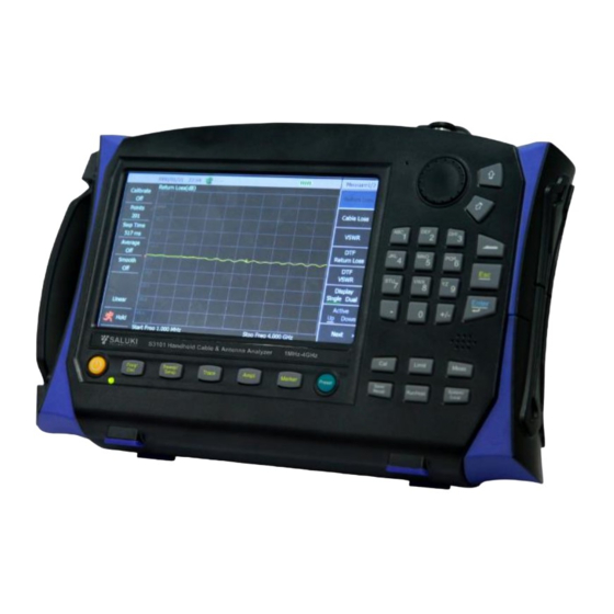
3.1. Front Panel Overview This Section will give a detailed introduction to the front panel of S3101. You can get generally familiar with the basic application of the panel keyboard of the instrument by reading it. The front panel of S3101 Cable & Antenna Analyzer is as shown below: Figure 3-1 Front Panel of S3101 Cable &... -
Page 14: Function Key Area
Tel: 886.909 602 109 Email: sales@salukitec.com www.salukitec.com : Used to start up or shut down the instrument. 【Preset】: Used to reset and restore the system to default initial state. 3.1.2. Function Key Area Figure 3-3 Schematic Diagram of Function Key Area 【Freq/Dist】: Used to set the measurement parameters, including frequency parameter, signal standard, distance parameter and ... -
Page 15: Other Keys
Tel: 886.909 602 109 Email: sales@salukitec.com www.salukitec.com Figure 3-4 Numeric Key Area Numeric (character) keys are used to input the values while setting frequency, marker, distance, amplitude and other parameters, and then press the corresponding unit key or Enter key to complete the input. There are 2 or 3 characters printed on the upper left corner of each numerical key and when the user intends to input characters, press them in quick succession to switch between numbers and characters. -
Page 16: Knob
Recommended Figure 3-6 Knob Operation 3.2.Top Panel Overview The top panel of S3101 Cable & Antenna Analyzer is as shown in Figure 3-7, including power interface, digital interface and test port. Figure 3-7 Top Panels 3.2.1. Power Interface Used for external DC power input. DC output from AC-DC adapter is used to power the Analyzer. The conductor inside external power interface is positive, with external conductor grounded. -
Page 17: Digital Interface
3.3.Screen Area Overview S3101 is provided with a 7-inch HB TFT true color LED with the function of touch screen and supports soft-key operations of applications through touch screen. The touch screen display area is as shown in Figure 3-11. Additionally, it provides different settings with different... -
Page 18: System Status Bar
Tel: 886.909 602 109 Email: sales@salukitec.com www.salukitec.com color contrast corresponding to different testing environment such as outdoor, nighttime, and normal testing environment. Figure 3-11 Touch Screen Display Area 3.3.1. System Status Bar Figure 3-12 System Status Bar Analyzer system date and time: Operators can set or change through 【System/Local】→[SET]→[Date/Time]. GPS display area: Operators can connect the GPS antenna and then turn on GPS through 【System/Local】→[GPS]→[GPS On Off]. -
Page 19: Trace Display Area
Tel: 886.909 602 109 Email: sales@salukitec.com www.salukitec.com Figure 3-14 Information Display Area Information display area mainly includes calibration On/Off, sweep point, sweep time and run/hold, etc. The area is mainly to provide operators with setting information about the sweep traces in the current drawing area; and operators can click the appropriate area to reset those information. -
Page 20: Menu Bar
3.4.Battery S3101 Cable & Antenna Analyzer is equipped with a rechargeable lithium-ion battery with a large capacity with operating time of up to more than 8 hours (Typ.). In order to assure the service life, the battery shall be taken out of the battery compartment in transport and long-term storage. -
Page 21: Viewing Battery Status
If only 1 bar left, please timely charge the battery. 3.4.3. Charging a Battery User can recharge the battery in the S3101 Cable & Antenna Analyzer while the analyzer is operating or when it is turned off. The charging procedures are as follows: Install the battery in the Analyzer. -
Page 22: Turn On/Off S3101
Analyzer displays startup screen. S3101 will take about 20 seconds to boot the start system and perform a series of self-test program, then the instrument enters the main program initialization interface and displays “Initializing, please wait……” After the main program starts, it will show an internal self-test report, and the user can observe whether the instrument is working properly. -
Page 23: Calibration
Tel: 886.909 602 109 Email: sales@salukitec.com www.salukitec.com 4. Calibration S3101 Cable & Antenna Analyzer shall be calibrated before measurement. Calibration can minimize the measurement error and improve the measurement accuracy of the tester. S3101 provides 2 calibration method Mechanical Calibration ... - Page 24 Tel: 886.909 602 109 Email: sales@salukitec.com www.salukitec.com Figure 4-2 Calibration Short Standard Disconnect the open standard with the calibration port, connect the short standard, and press [Short] button, then the screen will prompt “[SHORT] Measuring...”. After completing short standard measurement, the [Short] button on the right side of the menu bar is underlined as [Short], and the prompt massage saying ““Please connect [LOAD], and start calibrating by pressing corresponding soft key”.
-
Page 25: Embedded Calibration Kit
Tel: 886.909 602 109 Email: sales@salukitec.com www.salukitec.com Figure 4-4 Calibration Switch is on 4.2.Embedded calibration kit 4.2.1. Introduction Operators can quickly perform “one-click” single-port calibration by embedded electronic calibration, which is not only of simple operation and high precision calibration, but also able to adapt to the environment temperature of 0℃ to +50℃, significantly improving the test efficiency. - Page 26 Tel: 886.909 602 109 Email: sales@salukitec.com www.salukitec.com Figure 4-5 Start to Perform Embedded Calibration After completing calibration, the display interface shows the prompt saying “Finish embedded calibration ! ” and the calibration status automatically displays from “OFF” to “ON” as shown in Figure 4-6. Figure 4-6 Complete Embedded Calibration...
-
Page 27: General Operations
Tel: 886.909 602 109 Email: sales@salukitec.com www.salukitec.com 5. General Operations This Section gives a description of how to set the frequency, marker and limit, etc. parameters of S3101 Cable & Antenna Analyzer, to facilitate operators to understand the basic operation of the Analyzer. 5.1.Frequency When the measurement format of the Analyzer is return loss, cable loss and phase, Smith chart, press 【Freq/Dist】... -
Page 28: Amplitude
Tel: 886.909 602 109 Email: sales@salukitec.com www.salukitec.com Click the touch screen [Start Dist] menu to input start distance by turning the knob, 【↑】 or 【↓】 or numeric keys. When numeric keys are used to input the frequency value, the menu area displays the unit menu [M], and then click menu [M] or press 【Enter】 key to complete inputting the start distance;... -
Page 29: Sweep
5.4.2. Set sweep mode: S3101 Cable & Antenna Analyzer provides two sweeping modes including linear sweep and list sweep, and operators can realize the switching of sweep modes by [Sweep Mode Linear List] menu. Before realizing the list sweep, first edit the list to build a list of information to be swept, and then use [Sweep Mode Linear List] to do switching. -
Page 30: Set Sweep Time
5.4.3. Set sweep time: The sweep time of S3101 Cable & Antenna Analyzer provides two modes, automatic and manual modes. In automatic mode, the Analyzer calculates the minimum time required for sweeping one screen based on the current state of the instrument. Operators can click [Sweep Time Auto Man] menu to switch to manual mode, and in this case complete sweep settings as needed. -
Page 31: Set [Avg/Bw]
Tel: 886.909 602 109 Email: sales@salukitec.com www.salukitec.com The default sweep point of S3101 Cable & Antenna Analyzer is 201, and operators can set the desired sweep points arbitrarily within 2 to 4001 according to the testing requirements. The specific sweep steps are as follows: Press 【Sweep/Setup】... -
Page 32: Trace Smoothing
Trace smoothing is displayed through the average of adjacent data points, and the ratio of adjacent data points to be averaged and total points is called smooth aperture. S3101 Cable & Antenna Analyzer sets the smooth aperture in a manner of percentage. Smoothing function can reduce the noise peak-peak value on the measurement data track without significantly increasing the sweep time. -
Page 33: Limit
Tel: 886.909 602 109 Email: sales@salukitec.com www.salukitec.com 5.6.Limit Limit function is available only for the measurement formats of return loss, DTF, cable loss and phase, and the sweep mode of linear sweep. Limit test function can visually show whether the measured data exceeds the amplitude range represented by limit lines. Joined by multi-segments, limit line is edited via editing the limit value. -
Page 34: Limit Line Store & Recall
Tel: 886.909 602 109 Email: sales@salukitec.com www.salukitec.com Additionally, during editing process, the limit test function has opened automatically, a single or all limit point can be deleted by clicking on [Del Point] or [Del All]; when there is no limit point, the limit test will automatically close. Figure 5-11 shows the limit line test fails. Figure 5-11 Limit Test 5.6.3. -
Page 35: Move Marker
Tel: 886.909 602 109 Email: sales@salukitec.com www.salukitec.com 5.7.2. Move marker Use the above “Turn on a Marker” method to select the marker to be moved, making it the currently activated marker; Input the marker frequency value (or distance value) directly via numeric keys, press the appropriate units menu to complete marker movement;... -
Page 36: Quick Marker Operation
Tel: 886.909 602 109 Email: sales@salukitec.com www.salukitec.com Figure 5-14 Marker Function Schematic Diagram 5.7.6. Quick marker operation Press 【Marker】 key to enter marker menu bar, it opens Marker 1 by default; Click [Marker 1 2 3 4 5 6] menu to select Marker 2, and then press [Marker Off On] to activate Marker M2; Click [Marker Options] menu to select [M5 Peak [M1, M2]], then M5 executes the peak search between M1 and M2;... -
Page 37: Display
Tel: 886.909 602 109 Email: sales@salukitec.com www.salukitec.com 5.8.Display S3101 Cable & Antenna Analyzer enables simultaneous display of two data windows, and each window can display data in different formats. 5.8.1. Open dual window Press【Meas】to enter the measurement menu bar; Click [Display Window Single Dual] menu to switch window display mode, the switch of windows numbers can be seen on the screen correspondingly. -
Page 38: Trace
Tel: 886.909 602 109 Email: sales@salukitec.com www.salukitec.com Figure 5-16 Simultaneous Display of Two Data Formats Each window can set separately the trace marker. Frequency setting of the two windows is in synchronized association DTF parameters of the two windows are in synchronized association. ... -
Page 39: Trace Display
Tel: 886.909 602 109 Email: sales@salukitec.com www.salukitec.com Obtain a reference trace with reference to 5.9.1; Click [Data - Mem] key, then the drawing area shows the corresponding traces by subtracting the stored data from the current measured data to realize the differential value calculation press [Data/Mem] key, then the drawing area displays the corresponding traces by divorcing store data from the measured data to achieve the ratio operation. -
Page 40: Cable & Antenna Test
& antenna test in detail. After power on the S3101 Cable & Antenna Analyzer, the application program enters the antenna test function by default. If the operators have entered the power meter test function, press [MEAS MODE] menu under 【System/Local】 to switch to the antenna test function. -
Page 41: Cable Loss Measurement Setting
Tel: 886.909 602 109 Email: sales@salukitec.com www.salukitec.com Figure 6-1 Return Loss Measurement 6.3.Cable Loss Measurement Setting Press 【Meas】 key, click [Cable Loss] menu to set the instrument measurement format as cable loss. Press 【Freq/Dist】 key and input the frequency range to be measured, that is start frequency and stop frequency. Press 【Cal】... -
Page 42: Distance-To-Fault (Dtf) Measurement
6.4.Distance-To-Fault (DTF) Measurement In S3101 Cable & Antenna Analyzer, DTF measurement has two different display formats: DTF Return Loss and DTF VSWR. For the two same measurement processes, follow these steps to set. Press 【Meas】 key to set the instrument measurement format as DTF Return Loss or DTF VSWR. -
Page 43: Power Measurement
Frequency range of Power Measurement is determined by measurement frequency range of power probe. 7.2.Power Meter User Interface Introduction S3101 Cable & Antenna tester uses cable&antenna test mode in default. You may switch to Power Measurement mode following the steps below: Press 【System/Local】key and enter system menu bar;... -
Page 44: Main Display Area
Tel: 886.909 602 109 Email: sales@salukitec.com www.salukitec.com average Off/On, offset Off/On, corresponding measurement Off/On, and Run /Hold. This area mainly provides configuration information of power meter measurement inside current Main display area for operators. User may reset the information by clicking corresponding areas on touch screen. -
Page 45: Menu Bar
Tel: 886.909 602 109 Email: sales@salukitec.com www.salukitec.com Figure 10-3 Main display area 7.2.2. Menu Bar Menu bar is menu area in the right side of touch screen including two parts, menu bar title and menu items. Click function keys on front panel of Analyzer then menu bar of corresponding title will be spread in the right side of touch screen. -
Page 46: Measurement Parameters Setting
Tel: 886.909 602 109 Email: sales@salukitec.com www.salukitec.com 7.3.Measurement Parameters Setting 7.3.1. Frequency To obtain more convenient observation, you may set corresponding frequency range according to testing requirements for more accurate observation over power value of frequency point tested. Specific steps are as follows: Press 【Freq/Dist】to enter menu bar of frequency software;... -
Page 47: Calibration
Tel: 886.909 602 109 Email: sales@salukitec.com www.salukitec.com displayed. As shown in Figure 10-6: Figure 10-6 Amplitude Setting There are two amplitude setting methods as shown below: Manual setting: operators set the maximum value and the minimum value on power meter dial by themselves. Detailed operation is ... - Page 48 Tel: 886.909 602 109 Email: sales@salukitec.com www.salukitec.com Click [Zero] menu, the screen will indicate “Calibration”; “Finish calibration ! ” in a few seconds to indicate zero calibration is completed. As shown in Figure 10-7: Figure 10-7 Power Meter Calibration...
-
Page 49: Document Operation
8. Document operation 8.1.Introduction This chapter mainly introduces document management function and menu structure of corresponding 【Save/Recall】】key of S3101 Cable & Antenna Analyzer. You may perform operations such as saving, recalling, copying, and deleting etc. to internal memory of Analyzer, external extension storage devices and documents between them via submenu. - Page 50 Tel: 886.909 602 109 Email: sales@salukitec.com www.salukitec.com Press 【Save/Recall】key. Click [Save State] menu on Save/Recall menu bar on touch screen to bring up a dialog box “Input State Name”. You may input an appropriate status name in dialog box and click “Confirm key on screen or press【Enter】 key and complete status storage. As shown in the following figure: Figure 8-2 Status Storage For more convenient operation, you may recall previous status stored.
-
Page 51: Recall Trace
Tel: 886.909 602 109 Email: sales@salukitec.com www.salukitec.com 8.4.Recall Trace You may complete corresponding documents storage according to your own needs after selecting document storage location. This part mainly introduces trace save and recall. Trace save steps are as below: Press 【Save/Recall】】key. Click [Save Trace] menu to bring up a dialog box “Input Trace Name”. -
Page 52: Screen Shot
Tel: 886.909 602 109 Email: sales@salukitec.com www.salukitec.com conveniently; you may also click [Del] menu to delete some trace. You may click [Del all] menu to delete all traces. You may recall previous-stored traces (Traces recalled displayed are green in color) and perform comparison with currently measured trace via menu under 【Trace】key. -
Page 53: Document Management
Tel: 886.909 602 109 Email: sales@salukitec.com www.salukitec.com 8.6.Document Management Document management function is used to transfer, delete, or archive stored testing data, documents or images. Corresponding operation steps are as follows: Press 【Save/Recall】】key and enter Save/Recall menu bar. Click [File Mgmnt] menu item to bring up a dialog box of document management, menu bar will enter “File Mgmnt” menu, as shown in Figure 5-8. -
Page 54: System Management
Figure 9-1 Equipment Remote Control TEST 9.2.Measurement Mode S3101 Cable & Antenna Analyzer supports two measurement modes, cable & antenna test and power meter test. You may select testing mode according to your needs. Measurement mode selection steps are as follows: Press 【System/Local】key and enter system menu bar;... -
Page 55: Tip
Figure 9-2 Measurement Mode Selection 9.3.TIP S3101 supports label function. You may add an appropriate tip for current measured result in order to mark pictures when taking Print Screen. Label setting steps are as follows: Press 【System/Local】and enter system menu bar;... -
Page 56: Power Saving Mode
9.4.Power Saving Mode Considering LCD screen service life and power saving principle, S3101 Cable & Antenna Analyzer provides two power-saving modes, sleep mode and shutdown mode. You may select appropriate power saving mode according to self-test outcome. So-called sleep mode refers to a status, which will be automatically set by system according to time period set by operators if long time no operation occurred. -
Page 57: Display
Figure 9-5 System Timing Shutdown Function 9.5.Display To better handle different testing scenarios for operators, S3101 Cable & Antenna Analyzer provides several kinds of display functions and backlight brightness adjustment function. You may adjust display and brightness of instrument according to testing environment. - Page 58 Tel: 886.909 602 109 Email: sales@salukitec.com www.salukitec.com Figure 9-7 Outdoor Mode Figure 9-8 Night Mode Apart from display mode selection, Analyzer also provides screen brightness adjustment function. You may adjust screen brightness using this function under the same display mode. Detailed operating steps are as follows: Press 【System/Local】key and enter system menu bar;...
-
Page 59: Gps Function
Figure 9-9 Screen Brightness Adjustment 9.6.GPS Function S3101 Cable & Antenna Analyzer adds GPS function and supports connecting external GPS antenna to check geographical position where Analyzer locates. It includes information such as latitude, latitudinal hemisphere, longitude, longitudinal hemisphere, altitude, date, and time etc. -
Page 60: Setup
9.7.Setup 9.7.1. Date & Time S3101 Cable & Antenna Analyzer provides system time setting function. System time setting steps of Analyzer are as follows: Press【System/Local】key and enter system menu bar; Click [Config] menu and enter setup menu bar; Click [Date & Time] menu to bring up a dialog box of “Set Date and Time”. You may edit it with [Prev], [Next], knobs or selecting the content to be edited by clicking directly. - Page 61 Tel: 886.909 602 109 Email: sales@salukitec.com www.salukitec.com Figure 9-12 LAN—IP Configuration Click [Subnet Mask] menu on menu bar and switch cursor to subnet mask configuration column. Set subnet mask of instrument with numeric keys; as shown in the following figure: Figure 9-13 LAN—Subnet Mask Click [Gateway] menu on menu bar and switch setting cursor to Gateway column;...
-
Page 62: Touch Screen Calibration
Tel: 886.909 602 109 Email: sales@salukitec.com www.salukitec.com Figure 9-14 LAN—Gateway After configuration is completed, click “OK” key or 【Enter】key to complete LAN setting. 9.7.3. Touch Screen Calibration Touch precision of touch screen will be calibrated before delivery. However, you may recalibrate touch screen for low precision of touch screen response caused by accident. -
Page 63: Software Update
Tel: 886.909 602 109 Email: sales@salukitec.com www.salukitec.com Figure 6-15 Combination Key You may switch the menu circled by red frame with【↑】【↓】keys and locate it to [Config] menu. Press【Enter】 key and enter setting menu bar; Circle the red frame to [Touch Screen Cal] menu according to similar operation in Step 2. Press【 Enter】 key to bring up calibration page of touch screen. -
Page 64: Frequency Reference (10Mhz)
9.9.Frequency Reference (10MHz) S3101 Cable & Antenna Analyzer provides input/output interface for 10MHz reference clock. You may use Analyzer to provide 10MHz reference clock for other Analyzers. You may also use external 10MHz clock for this instrument. Operating steps of 10MHz reference clock input/output function are as below: Press 【System/Local】key and enter system menu bar;... -
Page 65: Measurement Guide
9.10. Measurement Guide S3101 Cable & Antenna Analyzer provides measurement guide function (This function is not applicable under power meter measurement mode.) for faster and more convenient master of basic operation of several measurement format. You may get the knowledge of basic measurement setting etc. - Page 66 Tel: 886.909 602 109 Email: sales@salukitec.com www.salukitec.com Figure 9-19 Measurement Guide...
-
Page 67: Software Toolkit
10.1. Software Description The software toolkit of S3101 Cable & Antenna Feeder Tester is mainly applied to control S3101A/B through computer, and realize reading, saving and comparing of the curve. All of those are convenient for operators to analyze the remote data, and for analyzers to monitor and maintain system effectively on PC. -
Page 68: Trace Collection & Storage
10.2.2. Trace collection refers to gather the test curves of S3101 in real time, which are then displayed in window of the software toolkit. Click the 【Remote Ctrl】tab, and then select the【Start】key in the【Trace Capture】group to start to collect traces, as shown in Figure 10-4. -
Page 69: Setting Of Sweeping Parameters
Tel: 886.909 602 109 Email: sales@salukitec.com www.salukitec.com Figure 10-5 Trace Capture Window Click the【 Stop 】 key, or directly close the trace collection window to stop the collection. 【Save】can realize the storage of the collected current trace data. Click this key, and then select the destination folder and input the file name in the popped-up dialog box of “Save As…”. -
Page 70: Remote Calibration
Tel: 886.909 602 109 Email: sales@salukitec.com www.salukitec.com Figure 10-7 Measurement Format Set In the【DTF】group, click【Set】to pop up the dialog box of “DTF Setting”, as shown in Figure 10-8, and input the corresponding parameters and then press the【OK】key to finish the setting. Figure 10-8 Dialog Box of DTF Parameter Setting Remote Calibration 10.2.4. -
Page 71: Trace Analysis
Tel: 886.909 602 109 Email: sales@salukitec.com www.salukitec.com Figure 10-10 Dialog Box of Calibrate Trace Analysis 10.2.5. Trace analysis mainly realizes functions such as the reading of measured values, details observation of trace, trace operations, etc. As for trace analysis function, click the【Trace Analysis】tab, which includes【File】,【Scale】,【Enlarge Drawing】,【Trace Math】and 【Marker】, as shown in Figure 10-11. - Page 72 Tel: 886.909 602 109 Email: sales@salukitec.com www.salukitec.com Figure 10-13 Dialog Box of “Open trace file” “Dev Trace File” is used for opening the trace files stored in the file. Click this menu item to pop up the dialog box of “Open Dev Trace File”, as shown in Figure 10-14.
- Page 73 Tel: 886.909 602 109 Email: sales@salukitec.com www.salukitec.com Figure 10-15 【Enlarge Drawing】 Group Figure 10-16 Use of Drawing Magnification Function Trace Operation Trace operation needs to be carried out between two traces. When using this function, it needs to open two trace files, and then drag your mouse in a trace window to another one in order to make two traces stay within the same window, as shown in Figure 10-17.
-
Page 74: File Transfer
Tel: 886.909 602 109 Email: sales@salukitec.com www.salukitec.com be deleted by clicking the【Delete Drag Trace】key. After the trace is dragged in (or when the trace is directly deleted), it can calculate the two traces in the top window in the Figure 10-17: make the top window activated, and click the addition, subtraction, multiplication, and division keys in the【Trace Math】group to realize the corresponding operation, with calculation result displayed as blue curve, as shown in Figure 10-18. -
Page 75: Check The Software Version
Tel: 886.909 602 109 Email: sales@salukitec.com www.salukitec.com Figure 10-20 【FILE TRANS】Tab Figure 10-21 Dialog Box of Copy Document Check the Software Version 10.2.7. Click the “About” key, namely question mark key, in the upper right corner of the software to check its version and copyright information, as shown in Figure 10-22. -
Page 76: Generate The Test Report
Tel: 886.909 602 109 Email: sales@salukitec.com www.salukitec.com Figure 10-23 Key of Printing Function Generate the Test Report 10.2.9. Software toolkit can generate the test reports in “pdf” format, which include some common items besides the drawing of current trace window. Click the “Recent List” key in the upper left corner of software, to select the Report Setting and Report Generation in the drop-down list, as shown in Figure 10-24.
Need help?
Do you have a question about the S3101 and is the answer not in the manual?
Questions and answers