Table of Contents
Advertisement
Quick Links
Advertisement
Table of Contents

Related Manuals for Saluki S3602 Series


Summary of Contents for Saluki S3602 Series
- Page 1 S3602 Series Vector Network Analyzer Quick Start Guide Saluki Technology Inc...
- Page 2 S3602C vector network analyzer (10MHz-43.5GHz) S3602D vector network analyzer (10MHz-50GHz) S3602E vector network analyzer (10MHz-67GHz) Options of the S3602 Series Vector network analyzer S3602A Part No. Name Description Set two 70dB programmable step attenuators for the...
- Page 3 Tel: 886. 909 602 109 Email: sales@salukitec.com www.salukitec.com extraction methods. Support NRZ, PAM-4 eye diagram drawing function. AFR Automatic Fixture Used for automatic testing and removal of single- S3602A-S07 Removal Option ended and balanced device measurement fixtures. For time-domain test, can locate and analyze the S3602A-S10 Time Domain Measurement discontinuous positions in devices, fixtures or...
- Page 4 Word or PPT report. Support a variety of Dk/Df extraction methods. Support NRZ, PAM-4 eye diagram drawing function. Special for Saluki VNA. Suitable for extension MiliMeter Extension Port Power S3602B-S06 modules with power adjustable function such as Control 3643P S-parameter extension module.
- Page 5 Tel: 886. 909 602 109 Email: sales@salukitec.com www.salukitec.com (Option 400, S80 is needed) Embedded LO Frequency For the measurement of embedded LO frequency S3602B-S84 Converter Measurement converters (Option 400, S82 or S83, S80 are needed) Gain Compression Two- For the gain compression two-dimension sweep test S3602B-S86 Dimension Sweep Measurement of amplifier...
- Page 6 Word or PPT report. Support a variety of Dk/Df extraction methods. Support NRZ, PAM-4 eye diagram drawing function. Special for Saluki VNA. Suitable for extension MiliMeter Extension Port Power S3602C-S06 modules with power adjustable function such as Control 3643P S-parameter extension module.
- Page 7 Word or PPT report. Support a variety of Dk/Df extraction methods. Support NRZ, PAM-4 eye diagram drawing function. Special for Saluki VNA. Suitable for extension MiliMeter Extension Port Power S3602D-S06 modules with power adjustable function such as Control 3643P S-parameter extension module.
- Page 8 Tel: 886. 909 602 109 Email: sales@salukitec.com www.salukitec.com AFR Automatic Fixture Used for automatic testing and removal of single- S3602D-S07 Removal Option ended and balanced device measurement fixtures. For time-domain test, can locate and analyze the S3602D-S10 Time Domain Measurement discontinuous positions in devices, fixtures or cables.
- Page 9 Word or PPT report. Support a variety of Dk/Df extraction methods. Support NRZ, PAM-4 eye diagram drawing function. Special for Saluki VNA. Suitable for extension MiliMeter Extension Port Power S3602E-S06 modules with power adjustable function such as Control 3643P S-parameter extension module.
- Page 10 Tel: 886. 909 602 109 Email: sales@salukitec.com www.salukitec.com (1.85/1.85) to 1.85mm (female) Top Rack Easy to build the system and use on the cabinet S3602E-061 Extension Workbench S3602E-EWT1 Extend 1 year warranty For S3602E main machine S3602E-3648- Extend 1 year warranty For S3602E-3648 link expansion device EWT1...
- Page 11 Saluki. Saluki Tech owns the copyright of this document which should not be modified or tampered by any organization or individual, or reproduced or transmitted for the purpose of making profit without its prior permission, otherwise Saluki will reserve the right to investigate and affix legal liability of infringement.
-
Page 12: Table Of Contents
Tel: 886. 909 602 109 Email: sales@salukitec.com www.salukitec.com Contents 1 Manual Navigation..............................14 1.1 About Manual.............................14 1.2 Related Documents............................ 14 2 Preparation for use..............................16 2.1 Preparation before operation........................16 2.1.1 Unpacking............................16 2.1.2 Instrument placement and measurement..................17 3 Instrument Appearance............................18 3.1 Front Panel.............................. - Page 13 Tel: 886. 909 602 109 Email: sales@salukitec.com www.salukitec.com 6.1.2 User Reset State..........................41 6.1.3 ReSetup of Analyzer........................42 6.2 Selection of Measurement Parameter......................42 6.2.1 Parameter S............................42 6.2.2 Ratio..............................43 6.2.3 Non-ratio Power Measurement....................... 44 6.2.4 Measurement mode of Trace change....................45 6.3 Setup of Frequency Range.........................
-
Page 14: Manual Navigation
S3602 series vector network analyzer to help the user make preparation for proper and safe operation. Instrument Appearance ● This chapter introduces the elements and functions of the front panel, rear panel and operation interface of S3602 series vector network analyzer. ● Instrument Power-on/off This chapter introduces S3602 turn on/off operations and system recovery. - Page 15 Tel: 886. 909 602 109 Email: sales@salukitec.com www.salukitec.com ● Overview ● Introduction to Use ● Operation guide ● Menu ● Fault diagnosis and repair ● Technical indicators and test methods ● Appendix Program control document This manual introduces the remote programming basis, SCPI basis, SCPI commands, programming examples, I/O drive function library, etc.
-
Page 16: Preparation For Use
Tel: 886. 909 602 109 Email: sales@salukitec.com www.salukitec.com Preparation for use Preparation before operation This chapter introduces the precautions for initial Setup and operation of S3602 series vector network analyzer. Warning Prevent damage to the instrument. In order to avoid electric shock, fire and personal injury: Do not open the casing without permission. -
Page 17: Instrument Placement And Measurement
Handling: The instrument and packing box are heavy and should be handled by two people with care. 2.1.2 Instrument placement and measurement In order to ensure normal functions of S3602 series vector network analyzer, pay attention to the following items: The operation location should meet the requirements of the operating environment and heat dissipation. ... -
Page 18: Instrument Appearance
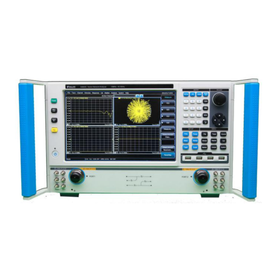
This chapter introduces the elements and functions of the front panel, rear panel and operation interface of S3602 series vector network analyzer. Front Panel This section introduces the structure and functions of the front panel of S3602 series vector network analyzer. The front panel is shown in the following figure. Fig. 3-1:Front Panel of S3602 Input Key zone The keys are used to enter measurement Setups, as shown in Fig 3-2. - Page 19 Tel: 886. 909 602 109 Email: sales@salukitec.com www.salukitec.com [OK] key Confirm the Setups and input values in the dialog box and close the dialog box, equivalent to the ―OK” button in the dialog box. [Cancel] key Ignore the Setups and input in the dialog box and close the dialog box, equivalent to the ―Cancel” button in the dialog box.
- Page 20 Tel: 886. 909 602 109 Email: sales@salukitec.com www.salukitec.com Rotate the knob to adjust the set value in the current active input box. [←] and [→] key Move left or right to select the menu. Switch the active options in the dialog box. [↑] and [↓] key Move up and down in the menu to select the menu item.
- Page 21 Tel: 886. 909 602 109 Email: sales@salukitec.com www.salukitec.com Fig.3- 5: Menu Key Zone of S3602 [File] key Open the main file menu. Following options will be displayed on screen: “Save”, “Call”, “Print”, “Minimize application program” and “Exit”. [Trace] key Open the main Trace menu. Following options will be displayed on screen: “New Trace”, “Delete Trace”, “Select Trace”, “Move Trace”, “Trace title”...
- Page 22 Tel: 886. 909 602 109 Email: sales@salukitec.com www.salukitec.com Function key zone include 4 function keys on the left side of the screen as shown in Fig. 3-6. Fig. 3-6: Function Key Zone of S3602 [Help] key Open the main help menu. Following options will be displayed on screen: “User manual”, “Programming manual”, “Technical support”, “Error information”...
-
Page 23: Rear Panel
RF source and receiver. so as to measure the tested device in bi-directions. The yellow light indicates the source output port. Fig. 3-9: Test Ports of Analyzer Rear Panel This section introduces the structure and functions of the rear panel of S3602 series vector network analyzer. The rear panel is shown in the following figure. - Page 24 Tel: 886. 909 602 109 Email: sales@salukitec.com www.salukitec.com Fig. 3-10: Rear Panel of Network Analyzer 10MHz reference connector 10MHZ reference output As shown in Fig. 3-11, the BNC (female) connector can be used for connection between the analyzer and external reference signal.
- Page 25 Tel: 886. 909 602 109 Email: sales@salukitec.com www.salukitec.com transmit and receive GPIB/SCPI commands. Fig. 3-12: General-interface Bus Connector LAN connector As shown in Fig. 3-13, this is a 10/100/1000BaseT Ethernet connector of standard 8-pin structure, and three data rates can be selected. Fig.
- Page 26 Tel: 886. 909 602 109 Email: sales@salukitec.com www.salukitec.com Fig. 3-15: VGA Connector LO and RF output connector As shown in Fig. 3-16, the 3.5mm female interface is used for LO output and RF output. The LO interface is used for internal LO signal output, and RF interface for RF source signal output.
- Page 27 Tel: 886. 909 602 109 Email: sales@salukitec.com www.salukitec.com Fig. 3-19: Automatic Test Interface Connector Extension interface connector As shown in Fig. 3-20, this interface is a 9-pin D-type female connector. Fig. 3-20: Extension Interface Connector External tester interface connector As shown in Fig. 3-21, this tester interface is a DB-25 female interface, including 13 addresses and data multiplexing lines, three control lines and one interruption control line, and is used to control the external tester (such as the external spread spectrum controller).
-
Page 28: Proper Use Of Connector
Tel: 886. 909 602 109 Email: sales@salukitec.com www.salukitec.com Fig.3-22: Trigger Input/Output Interface Connector 28V (BNC) interface connector As shown in Fig. 3-23, this BNC (female) connector can be used to drive a noise source. Fig.3-23: 28V (DC) Interface Connector Proper Use of Connector The connector is always required in various tests of the network analyzer. -
Page 29: Disconnection Method
Tel: 886. 909 602 109 Email: sales@salukitec.com www.salukitec.com Step 2 As shown in following fig below, horizontally move two connectors to make them connected smoothly. Tighten the connector nut by means of rotation (do not rotate the connector). Avoid relative rotation of connectors during connection. Step 3 As shown in following fig, complete the final connection by tightening with the torque wrench. - Page 30 Tel: 886. 909 602 109 Email: sales@salukitec.com www.salukitec.com Fig. 3-24: Use of Torque Wrench...
-
Page 31: Instrument Power-On/Off
Then the instrument can be operated. Prompt In order to meet the performance indicators of S3602 series vector network analyzer in cold start, preheat it more than 30 minutes before measurement. -
Page 32: Shutdown
Tel: 886. 909 602 109 Email: sales@salukitec.com www.salukitec.com Prompt Run the analyzer application program. The application program automatically run after the network analyzer started. If the application is closed, user can restart the program : Click [Start] in the task bar in the lower left corner of the screen. Point [Program] > Method 1 [Vector network analyzer]. - Page 33 Tel: 886. 909 602 109 Email: sales@salukitec.com www.salukitec.com Fig.4- 4 System Recovery Screen...
-
Page 34: Human Machine Interface
Tel: 886. 909 602 109 Email: sales@salukitec.com www.salukitec.com Human Machine Interface As shown in Fig. 5-1, the mouse can be used to realize the following operations. Click the menu bar to display the drop-down menu. Click the input toolbar to adjust the entered number. ... -
Page 35: Tool Bar
Tel: 886. 909 602 109 Email: sales@salukitec.com www.salukitec.com Current active channel Measurement parameter of active Trace Mathematical operation of active Trace Error correction status of active Trace If the average function is enabled, the average factor of the current active channel and the average times will ... - Page 36 Tel: 886. 909 602 109 Email: sales@salukitec.com www.salukitec.com d) Sweep control toolbar The buttons of the sweep control toolbar are respectively used to set the following modes of the active channel in sequence: Holding mode Single sweep Continuous sweep ...
- Page 37 Tel: 886. 909 602 109 Email: sales@salukitec.com www.salukitec.com 5.1.3 Table Area 1) Display the cursor, limit and segment table so that the user can observe and modify the Setups (except the cursor table). The list is displayed in the lower part of the window. Only one table can be displayed in each window.
-
Page 38: Display Contents
Tel: 886. 909 602 109 Email: sales@salukitec.com www.salukitec.com 2) Triggering of table display Menu path: [Response] > [Display]. Point to the [Tables] in the display sub-menu. Click the table to be triggered in the sub-menu. Tick this item to display the table and clear it to hide the table. Fig. -
Page 39: Title Bar
Tel: 886. 909 602 109 Email: sales@salukitec.com www.salukitec.com Scale Reference value The Trace state button can be used to set the corresponding Trace as the current active Trace so as to set the Trace. Point to the button and right-click the mouse. Delete the Trace or set the Trace scale, color and line through the right- click menu. - Page 40 Tel: 886. 909 602 109 Email: sales@salukitec.com www.salukitec.com control button. Click [Hide title bar] to hide all title bars on the screen. In this case, the display of measurement results on the screen can be maximized. Triggering of title bar display Menu path: [Response] >...
-
Page 41: Typical Application
Typical Application This chapter mainly describes the operation of S3602 series network analyzers in measurement, creation of the measurement of the known status by analyzer reSetup, selection of measurement Setup, adjustment of the analyzer display so as to better observe measurement results, specifically including: ●... -
Page 42: Resetup Of Analyzer
The [Preset] shortcut key is set in the functional key zone and shortcut menu bar. Selection of Measurement Parameter The following parameters can be set in an S3602 series vector network analyzer to measure the electrical characteristics of devices. S parameter (fixed ratio) ... -
Page 43: Ratio
Tel: 886. 909 602 109 Email: sales@salukitec.com www.salukitec.com indicates the proportion of two complex vectors, i.e. S , including the amplitude and phase information. The output/input output refers to the output signal port number of the tested device, and the input refers to the input signal port number of the tested device. -
Page 44: Non-Ratio Power Measurement
Tel: 886. 909 602 109 Email: sales@salukitec.com www.salukitec.com Fig. 6-4 Definition of Parameter 6.2.3 Non-ratio Power Measurement The absolute power of the receiver A, B, C, D, R1, R2, R3 and R4 can be measured in the non-ratio power measurement mode, however, the phase, group delay and other items under the ―average‖ function cannot be measured. -
Page 45: Measurement Mode Of Trace Change
Tel: 886. 909 602 109 Email: sales@salukitec.com www.salukitec.com g) [Automatically create window] check box If this check box is ticked and the number of Traces in the window exceeds 8, excessive Traces will be automatically created in a new window. If this check box is cleared and the number of Traces in the window exceeds 8, excessive Traces will not be created. -
Page 46: Setup Of Signal Power Level
The power level refers to the power level of the output signal of the test port. The power level indicators of the port of S3602 series vector network analyzer are as follows. Table 6-1 Power Level Indicators of Source Output Signal... - Page 47 Tel: 886. 909 602 109 Email: sales@salukitec.com www.salukitec.com Fig. 6-9 Setup of Power Level 2) Cutoff of port power Menu path: [Stimulus] > [Power] > [Power state ON/off]. Or, switch the power by changing the Setup of the [Power ON/off] check box in the [Power Setup] dialog box. 3) Manual Setup of attenuation Menu path: [Stimulus] >...
- Page 48 Tel: 886. 909 602 109 Email: sales@salukitec.com www.salukitec.com Unit of power slope: dB/GHz. Power slope Setup range: -2 to +2. 6) [Power and attenuation] dialog box a) [Power ON/off] check box If this check box is ticked, the port will normally output the power. If this check box is cleared, the port output power will be cut off.
-
Page 49: Setup Of Sweep
Tel: 886. 909 602 109 Email: sales@salukitec.com www.salukitec.com Setup of Sweep Sweep refers to the process of continuously measuring data points according to the Stimulus values in the specified sequence. 6.5.1 Overview of Sweep Types The network analyzer supports six Sweep types shown below. 1) Linear frequency This is the default Sweep type of the instrument. - Page 50 Tel: 886. 909 602 109 Email: sales@salukitec.com www.salukitec.com Fig. 6-10 Setup of Linear Frequency Sweep Type Setup of segment Sweep type Menu path: [Stimulus] > [Sweep] > [Sweep type]. Auxiliary menu bar: click [Segment Sweep] or select [Segment Sweep] in the [Setup type] dialog box. Fig.
-
Page 51: Sweep Time
Tel: 886. 909 602 109 Email: sales@salukitec.com www.salukitec.com Fig. 6-12 Segment Insertion and Deletion Editing of segment table Double-click the [State] box of the segment and select “ON” or “OFF” to open or close the segment. Double-click the [Starting Stimulus] box of the segment and enter the starting frequency of the segment. ... -
Page 52: Setup Of Sweep
Tel: 886. 909 602 109 Email: sales@salukitec.com www.salukitec.com Fig. 6-14 Setup of Sweep Time 6.5.4 Setup of Sweep 1) Sweep Setup Menu path: [Stimulus] > [Sweep] > [Sweep Setup]. The [Sweep Setup] dialog box will appear. Fig. 6-15 Sweep Setup 2) [Sweep Setup] dialog box a) [Channel] box Select the channel applicable to Sweep Setup. -
Page 53: Simple Trigger Setup
Tel: 886. 909 602 109 Email: sales@salukitec.com www.salukitec.com flexibility in trigger Setup. 6.6.1 Simple Trigger Setup Only the trigger mode of the current active channel can be set by simple trigger Setup. Menu path: [Stimulus] > [Trigger]. The trigger sub-menu will appear. Click [Continuous], [Single] or [Hold] in the sub-menu and select the trigger mode. -
Page 54: Trigger] Dialog Box
Tel: 886. 909 602 109 Email: sales@salukitec.com www.salukitec.com Fig. 6-18 Trigger Setup Dialog Box 6.6.3 [Trigger] Dialog Box 1) Trigger Setup options a) Trigger source zone The source of the channel trigger signal is determined by trigger source Setup of the trigger source zone. The effective trigger signal is generated when Sweep is not done by the vector network analyzer. - Page 55 Tel: 886. 909 602 109 Email: sales@salukitec.com www.salukitec.com trigger signal. [Channe] Next channel which is not in the holding mode will receive the trigger signal. After the current channel is measured, next channel will be selected automatically. Except the channel in the holding mode, all channels will be selected in sequence.
- Page 56 Tel: 886. 909 602 109 Email: sales@salukitec.com www.salukitec.com Set the external trigger signal input interface, including the BNC interface and automatic test interface (18-pin). [Level/edge] Set the trigger mode of the external trigger signal, including high level, low level, rising edge and falling edge. [Ready to enable trigger signal received before triggering] ...
- Page 57 Tel: 886. 909 602 109 Email: sales@salukitec.com www.salukitec.com Fig. 6-19 Auxiliary 1/2 Trigger Dialog Box 4) Pulse trigger options a) Synchronous pulse input zone Select the internal or external source to synchronize the internal pulse generator of the analyzer. [Synchronization] ...
-
Page 58: Setup Of Data Format And Scale
Tel: 886. 909 602 109 Email: sales@salukitec.com www.salukitec.com It is used to measure the broadband synchronization pulse. When this function is enabled, the pulse generator output and data collection are allowed to be synchronized. [Delay] Set the delay time before collection of AD data. Fig. - Page 59 Tel: 886. 909 602 109 Email: sales@salukitec.com www.salukitec.com Fig. 6-21 Rectangular Coordinate Format a)Logarithmic amplitude format Display the amplitude information (no phase information). Y-axis unit: dB Applicable typical measurement: return loss, insertion loss and gain. b)Phase format Display the phase information (no amplitude information).
- Page 60 Tel: 886. 909 602 109 Email: sales@salukitec.com www.salukitec.com It is similar to the linear amplitude format, but both the positive value and negative value can be displayed. Y-axis: no unit. Applicable typical measurement: time domain and auxiliary input voltage for maintenance purposes. ...
-
Page 61: Data Format Setup
Tel: 886. 909 602 109 Email: sales@salukitec.com www.salukitec.com Fig. 6-23 Smith Chart Format The horizontal axis of the center of Smith chart represents the pure resistance, and the center of the horizontal axis represents the system impedance. The leftmost resistance on the horizontal axis is zero, indicating a short circuit. -
Page 62: Observation Of Multiple Traces And Opening Of Multiple Channels
Tel: 886. 909 602 109 Email: sales@salukitec.com www.salukitec.com Fig. 6-24 Setup of Scale 2) Scale Setup dialog box a)Scale zone [Scale] box Enter the set scale value. [Automatic scale] button Click the [Automatic scale] button. The analyzer will automatically select the vertical scale to better display the active Trace in the vertical grid of the screen. - Page 63 Tel: 886. 909 602 109 Email: sales@salukitec.com www.salukitec.com Fig. 6-25 Preconfigured Window Arrangement Setup A Four Traces will be created in Window 1: S11, S21, S12 and S22, in the logarithmic format in Channel 1. Setup B Four Traces will be created in four windows, in the logarithmic format in Channel 1. S11 will be displayed in Window 1, S21 in Window 2, S12 in Window 3 and S22 in Window 4.
-
Page 64: Data Output
Menu path: [Response] > [Display]. The display sub-menu will pop up. Select the window arrangement mode in the display sub-menu. Fig. 6-26 Setup of Window Arrangement Data output 6.9.1 Saving and Calling of File S3602 series vector network analyzer supports the saving and calling of files in various formats. - Page 65 Tel: 886. 909 602 109 Email: sales@salukitec.com www.salukitec.com Save files Menu path: [File] > [Save] > [Save]/[Save as...]. Fig. 6-27 Save files Recall of file 1) Call status and calibration data: a) sta file The status data of the instrument are saved in the sta file, including the Setups, Trace data, limit line and cursor.
-
Page 66: Printing Of Measurement Contents
Tel: 886. 909 602 109 Email: sales@salukitec.com www.salukitec.com Fig. 6-28 File Calling 6.9.2 Printing of Measurement Contents The analyzer supports the output of measurement contents through the printer or printing into the specified file. The local or network printer can be used. The printer can be of parallel, serial or USB interface type. Add the printer in the WINDOWS operating system. - Page 67 Tel: 886. 909 602 109 Email: sales@salukitec.com www.salukitec.com After the printer is added and the print contents are set, measurement information can be output through the printer, as shown below: Menu path: [File] > [Print] > [Print...]. The print Setup dialog box will appear. Fig.
-
Page 68: Help
In addition, our customer support center can, at any time, assist the user to solve any problem in typical applications of S3602 series vector network analyzer. If you can provide the following information, we can find the solution more quickly and efficiently. - Page 69 Tel: 886. 909 602 109 Email: sales@salukitec.com www.salukitec.com If you cannot solve the problem of the network analyzer, contact us by phone or fax. If it is confirmed that the network analyzer needs to be returned for repair, pack the network analyzer with the original packing material and box according to the following steps: 1) Write fault details of the network analyzer and place it with the network analyzer into the packing box.
Need help?
Do you have a question about the S3602 Series and is the answer not in the manual?
Questions and answers