
Related Manuals for Saluki S5105 Series


Summary of Contents for Saluki S5105 Series
- Page 1 S5105 Series Microwave Multifunctional Analyzer User Manual Saluki Technology Inc.
- Page 2 CD (user manual, programming manual, USB driver, program-controlled function library, program-controlled example, and installation file required for program-controlled function library) Certificate of Conformity Options of the S5105 series microwave analyzer in addition to standard accessories: Part No. Name Description For testing RL, VSWR, Break point of Cable and...
- Page 3 Tel: 886.909 602 109 Email: sales@salukitec.com www.salukitec.com Part No. Name Description S5105-H11 3.5mm (F-M) Calibration Cable S5105-H12 2.4mm (F-F) Calibration Cable S5105-H13 2.4mm (F-M) Calibration Cable S5105-H14 S87230 USB Power Sensor, 9kHz-6GHz S5105-H15 S87231 USB Power Sensor, 10MHz-18GHz For High-precision Power Measurement S5105-H16 S87232 USB Power Sensor, 50MHz-26.5GHz...
- Page 4 Manual rests with Saluki. Saluki Tech owns the copyright of this User Manual which should not be modified or tampered by any organization or individual, or reproduced or transmitted for the purpose of making profit without its prior permission, otherwise Saluki will reserve the right to investigate and affix legal liability of infringement.
-
Page 5: Table Of Contents
Tel: 886.909 602 109 Email: sales@salukitec.com www.salukitec.com Contents Chapter I Overview..............................1 Section I Product Overview..........................1 Section II Safety precautions..........................2 Section III Environmental protection......................... 4 Section IV Other precautions..........................4 Part I Operation instruction............................6 Chapter II User instructions............................7 Section I Unpacking inspection.......................... - Page 6 Tel: 886.909 602 109 Email: sales@salukitec.com www.salukitec.com Section IX Menu Description..........................103 Section X Technical Specifications........................ 117 Section XI Recommended Test Method....................... 118 Chapter VI Antenna Feed Test Mode (Optional).................... 129 Section I Basic Operations..........................129 Section II Frequency Setting..........................131 Section III Amplitude/Ruler Setting....................... 131 Section IV Bandwidth Settings........................132 Section V Sweep Settings..........................
-
Page 7: Chapter I Overview
Tel: 886.909 602 109 Email: sales@salukitec.com www.salukitec.com Chapter I Overview Section 1 Product Overview With frequency range of 18GHz/26.5GHz/40GHz, S5105D/E/F series microwave multifunctional analyzer features small size, light weight, user-friendly, and high measurement accuracy and is capable of such functions as cable and antenna VSWR analysis, return loss analysis, transmission character, time domain measurement, discontinuous impedance point positioning, spectrum analyzer, power monitoring and vector voltage measurement, which is provided with two modes of power supply, namely, external power source and internal rechargeable battery, and LAN and USB ports for program... - Page 8 Tel: 886.909 602 109 Email: sales@salukitec.com www.salukitec.com Two types of USB2.0 ports available for portable storage device connection and PC communication respectively; One 10/100Mbps network port for local network establishment and remote control. Typical Applications 2.1 Multiple-field test Filter performance test ...
-
Page 9: Section Ii Safety Precautions
Tel: 886.909 602 109 Email: sales@salukitec.com www.salukitec.com Section 2 Safety precautions Please carefully read and strictly observe the following safety precautions! We will spare no effort to guarantee that all production processes meet the late safety standards and provide users with the high safety guarantee. The design and testing of our products and the auxiliary equipment used meet relevant safety standards, and a quality assurance system has been established to monitor the product quality and ensure the products to always comply with such standards. -
Page 10: Section Iii Environmental Protection
Scrap processing Components and parts replaced during maintenance and upgrading will be recycled by Saluki Technology Inc.; the scrapped instrument cannot be discarded or disposed at will, which must be recycled by Saluki Technology Inc. - Page 11 Tel: 886.909 602 109 Email: sales@salukitec.com www.salukitec.com In case of any instrument failure, do not disassemble it. Just send it back to the factory for maintenance. safety symbols shown below are used in the manual. Please get familiar with them and their meanings and read Part I of the manual at least first before operation, so as to guarantee personnel safety and instrument performance.
-
Page 12: Part I Operation Instruction
Tel: 886.909 602 109 Email: sales@salukitec.com www.salukitec.com Part I Operation instructions... -
Page 13: Chapter Ii User Instructions
Chapter II User instructions Thanks for using the S5105 series microwave multifunctional analyzer. Please read this chapter carefully to avoid any instrument damage or accident due to maloperation. In case of any problem, please contact us in time for quick solution. - Page 14 Tel: 886.909 602 109 Email: sales@salukitec.com www.salukitec.com 220V AC stabilized-voltage supply for the microwave analyzer, so as to avoid or reduce mutual interference between multiple equipment due to the shared power supply (especially any damage to the microwave analyzer due to peak pulse interference caused by high power equipment).
-
Page 15: Section Iii Battery Operation Instruction
Tel: 886.909 602 109 Email: sales@salukitec.com www.salukitec.com Electrostatic protection Electrostatic protection can always be ignored. Discharge of static electricity accumulated on the human body can damage the sensitive circuit component inside the instrument, lowering the instrument reliability dramatically. Even the undetected tiny static electricity discharge can damage the instrument permanently. -
Page 16: Section Iv Analyzer Startup And Shutdown
Tel: 886.909 602 109 Email: sales@salukitec.com www.salukitec.com after continuous operation of 12 months. The times of charging and discharging of the battery can be up to 300-500, but it will lose its utility in the end. The battery must be replaced if its operation time is obviously shorter than the normal one with full capacity. -
Page 17: Section V Routine Maintenance
Tel: 886.909 602 109 Email: sales@salukitec.com www.salukitec.com Keys marked with 【】 in the manual indicates hardkeys, namely, the keys ! on the front panel, for example, 【Freq】. Soft menus corresponding to NOTE: softkeys are marked with [], for example, [Start Freq]. analyzer startup Connect the microwave analyzer to the specified AC power supply via the specified 3-core power cord, or ensure it is provided with a battery with capacity of more than 10%. -
Page 18: Chapter Iii Basic Quick Start
Tel: 886.909 602 109 Email: sales@salukitec.com www.salukitec.com Chapter III Basic quick start The chapter introduces the basic quick start for the S5105D/E/F microwave analyzer for guiding users to quickly understand the basic operation method of the S5105D/E/F microwave analyzer. Section 1 Correct Use of Connectors Connectors are deemed to be used during various tests via the microwave analyzer, and the following precautions must be paid attention to in respect of connector operation: 1 Connector check... - Page 19 Tel: 886.909 602 109 Email: sales@salukitec.com www.salukitec.com As shown in Figure 3 -3, tighten the connectors with a torque wrench to complete the connection. Pay attention that the torque wrench should not exceed the initial folding point. Use an auxiliary wrench to prevent the connector from rotating. Hold Figure 3 -3 Finishing the connection with a torque wrench Disconnection method...
-
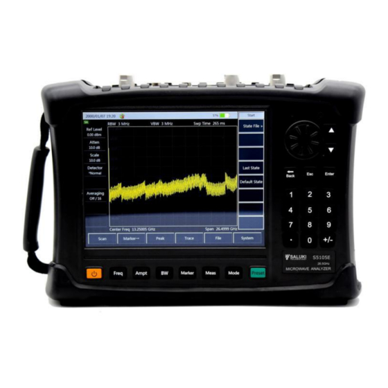
Page 20: Section Ii Front Panel
Tel: 886.909 602 109 Email: sales@salukitec.com www.salukitec.com Section 2 front panel The appearance of the front panel of the S5105D/E/F microwave analyzer is shown in Figure 3-5: Figure 3-5 Front panel of S5105D/E/F microwave analyzer Key description Function key area It is used to change the measurement parameter setting, including six keys: Freq Bandwidth... - Page 21 Tel: 886.909 602 109 Email: sales@salukitec.com www.salukitec.com Set such parameters as the reference, ratio, max. and min. values, relative measurement on/off status and offset in the power monitoring mode and USB Power Meter mode. Set the preamplifier on/off status in the power monitoring mode. 【...
- Page 22 Tel: 886.909 602 109 Email: sales@salukitec.com www.salukitec.com If the microwave analyzer is connected an external power supply, provided with a battery with capacity of less than 100%, and in the start-up status, the indicator light flashes in green, indicating the microwave analyzer is charging the battery now; after charging fully, the microwave analyzer stop charging, and the indicator light changes into green and is on constantly.
- Page 23 Tel: 886.909 602 109 Email: sales@salukitec.com www.salukitec.com It is used to enter such parameter values as the frequency, amplitude and marker, and press corresponding unit key or the OK key to complete the input. Reset key It is used for system resetting, system restart, recovery or restoration. To reset the system, just press the key and then release it.
- Page 24 Tel: 886.909 602 109 Email: sales@salukitec.com www.salukitec.com Figure 3-9 Port panel External power port It is used for external DC power input. Supply power to the microwave analyzer via the DC output of the AC-DC adapter or DC power supply. The internal conductor of the external power supply port is the positive pole, while the external conductor is grounded.
- Page 25 Tel: 886.909 602 109 Email: sales@salukitec.com www.salukitec.com Earphone port The S5105D/E/F microwave analyzer is provided with a standard 3.5mm/3-line earphone port for outputting the sound modulated via FM/AM/SSB. If the port is not connected to the earphone, the sound is output via the speaker of the microwave analyzer; when it is connected to the earphone, the sound output is switched from the speaker to the earphone automatically.
-
Page 26: Section Iii System Setting
Tel: 886.909 602 109 Email: sales@salukitec.com www.salukitec.com on top of the grid, and the start/stop frequencies displayed at the bottom. The trace is displayed in coordinate grid in the spectrum analyzer mode. Scale values and mark information are displayed in the left and upper right of the grid respectively. - Page 27 Tel: 886.909 602 109 Email: sales@salukitec.com www.salukitec.com Click [System]→[Info] to pop up the instrument serial number window, displaying such version information as the product model, serial number, application program and firmware program. Click 【OK】to close the window. Self test The S5105D/E/F microwave analyzer is provided with a self test function, which can test the working status and internal environment temperature of each component in the microwave analyzer and provide test information after the self test program is activated.
- Page 28 Tel: 886.909 602 109 Email: sales@salukitec.com www.salukitec.com Press [GPS Off/On] to switch the GPS status, and enable the GPS function. Press [GPS Info] to view detailed GPS information. System language selection Press [System]→[Language] to enter the language selection interface of the system. Press [Simplified Chinese] or [English] to set current interface operation language.
-
Page 29: Section Iv Reset Setting
Tel: 886.909 602 109 Email: sales@salukitec.com www.salukitec.com The S5105D/E/F microwave analyzer can also output the internal reference as follows: Press [Ref Output Off/On] to enable or disable the reference output function. 13 Set reference output The S5105D/E/F microwave analyzer can provide external device with a reference output of 10MHz via also the “10MHz input/output”... - Page 30 Tel: 886.909 602 109 Email: sales@salukitec.com www.salukitec.com System menu structure System Power Saver Display Sleep Version serial number Outdoor@Mode Shutdown Time Self-test Night@ModeMode > Power Saver Normal@ModeMode > Display Back Brightness > Auto/Manu LANG Off/On > LANG Back Chinese GPS Info >...
- Page 31 Tel: 886.909 602 109 Email: sales@salukitec.com www.salukitec.com System menu 【System】 Click it to switch the microwave analyzer in the remote control mode back to the local operation mode, or pop up system-related soft menus if the microwave analyzer is in the local operating mode, including [Info], [Self Test], [Power Saver], [Display], [GPS], [Language], [Set], [Freq Ref Int/Ext], [Ref Output Off/On ] and [Error Log] [Info]...
-
Page 32: Section V File Management
Tel: 886.909 602 109 Email: sales@salukitec.com www.salukitec.com To pop up the interface language selection menu for analyzer operation with two options, namely, simplified Chinese and English. [Chinese] To set the operation interface language to simplified Chinese, which is also the default language of the microwave analyzer. - Page 33 Tel: 886.909 602 109 Email: sales@salukitec.com www.salukitec.com status. To recall the state set before last shutdown, press [File]→[Recall@State>]→[Last State];to recall the default system state, press [File]→[Recall@State>]→[Default State];to recall the saved state, press [File]→[Recall@State>]→[State File>] to pop up the state list dialog box, select the state to be recalled directly via the up/down key, rotary knob or touchscreen, and then press [OK] or [Recall] to complete the state recalling.
- Page 34 Tel: 886.909 602 109 Email: sales@salukitec.com www.salukitec.com File Management Menu Structure File Recall Save State Page Up Save Trace > Trace Recall Status Page Down Data > Save Trace Recall (.csv) > Recall Trace Delete Back Print Screen Del All >...
- Page 35 Tel: 886.909 602 109 Email: sales@salukitec.com www.salukitec.com File Management Menu Description [File] [Save State] Save current sweep status parameters. [Recall Status>] Read the file saved with state parameters, and recall relevant state parameter for current sweep. [Page Up] Turn the page upward and view the saved state file. [Page Down] Turn the page downward and view the saved state file.
- Page 36 Tel: 886.909 602 109 Email: sales@salukitec.com www.salukitec.com Turn the page downward and view the saved trace file. [Delete] Delete the selected trace file. [Del All] Delete all trace files saved in the spectrum analyzer mode. [Print Screen] Get the printscreen. [Location Int] Select the saving medium, which is the memory of the system internally by default and the USB disk externally.
-
Page 37: Chapter Iv Vector Network Analysis Mode
Tel: 886.909 602 109 Email: sales@salukitec.com www.salukitec.com Chapter IV Vector network analyzer mode Section 1 Basic Operation The section introduces the measurement function and measurement method of the S5105D/E/F microwave analyzer in the vector network analyzer mode (hereinafter referred to as the “VNA”), so that users can have a brief understanding on the test operation and conduct basic measurement. - Page 38 Tel: 886.909 602 109 Email: sales@salukitec.com www.salukitec.com measurements. In case of any change in the instrument measurement setting (such as the frequency range and sweep points) or port extension cable added to the test port, recalibration is required. The full 2 ports standard adopted by the microwave analyzer can eliminate the reflection tracking error, transmission tracking error, directional error, source matching error and load matching error, ensuring measurement with high accuracy.
-
Page 39: Section Ii Frequency Setting
Tel: 886.909 602 109 Email: sales@salukitec.com www.salukitec.com Saving and recalling measurements The microwave analyzer can save the setting status and measurement data to the internal memory, external USB disk or SD card, and recall the setting status and measurement data of the instrument from the internal memory, external USB disk or SD card. -
Page 40: Section Iii Amplitude/ Scaleplate Setting
Tel: 886.909 602 109 Email: sales@salukitec.com www.salukitec.com Section 3 Amplitude/ scaleplate setting This section introduces the detailed setting method for measurement amplitude (including scale type) of the S5105D/E/F microwave 【Amplitude】analyzer in the VNA mode by pressing to open the amplitude and scale setting menu. -
Page 41: Section V Sweep Setting
Tel: 886.909 602 109 Email: sales@salukitec.com www.salukitec.com S5105D/E/F microwave analyzer in the VNA mode ranges from 1Hz to 100kHz, which changes at the 1, 3 or 10 steps. Reducing the IF bandwidth can lower the impact of the random noise on the measurements (reducing 10 times of the IF bandwidth can lower the noise base by 10dB), but it can prolong the sweep time. -
Page 42: Section Vi Trace Setting
Tel: 886.909 602 109 Email: sales@salukitec.com www.salukitec.com Section 6 Trace setting This section introduces the trace setting method of the S5105D/E/F microwave analyzer in the VNA mode, including trace opening, closing and calculation, as well as limit line usage. Trace display and calculation The trace display function can be used to control the contents and quantity of the trace displayed in the window. -
Page 43: Section Vii Marker Searching And Setting
Tel: 886.909 602 109 Email: sales@salukitec.com www.salukitec.com to complete the recalling. If the number of limit line storage files is large, press [Limit>] → [Recall >] → [Page Up], [Page Up] and find the limit line file to be recalled by page, and press [Limit>] → [Recall >] →... - Page 44 Tel: 886.909 602 109 Email: sales@salukitec.com www.salukitec.com dynamic To have a correct measurement, range the input signal power should be within the range. Figure 4-1 Dynamic range To lower the measurement uncertainty, the dynamic range of the microwave analyzer shall be larger than the response range of the DUT.
- Page 45 Tel: 886.909 602 109 Email: sales@salukitec.com www.salukitec.com extending the sweep time. Steps for setting the track smoothing: Press 【BW】 → [Smooth Off On] and input the smooth aperture with numeric keys. Reduce IF bandwidth The microwave analyzer converts the received response signal to a lower intermediate frequency signal for processing.
- Page 46 Tel: 886.909 602 109 Email: sales@salukitec.com www.salukitec.com Table 4-1 Error correction classification Correction type Corresponding Error corrected Standard piece required measurement type Freq Resp. Transmission Freq Resp. Transmission reflection measurement thorough method (with accuracy reflection via the open requirement). or short device Measure Response and isolation transmission...
- Page 47 Tel: 886.909 602 109 Email: sales@salukitec.com www.salukitec.com If the calibration is interrupted due to another menu is opened, press [Cal Cont] in the calibration menu to continue the calibration. Standard calibration kit During measurement calibration, the microwave analyzer will measure the actual and strictly-defined standard piece, and make comparison on the ideal “mode”...
- Page 48 Tel: 886.909 602 109 Email: sales@salukitec.com www.salukitec.com Cal>]→[Freq Resp.>]→[SHORT S11>] or [OPEN S22>] or [SHORT S22>], connect to the open- circuit device or short-circuit device at corresponding test port as per the prompt, and conduct the operation shown in steps f) and g). Only one standard piece can be measured at one time.
- Page 49 Tel: 886.909 602 109 Email: sales@salukitec.com www.salukitec.com connected and measured at this time. ! Do not use the standard piece of the open-circuit device or short-circuit NOTE: device for transmission response correction. Cables Microwave analyzer Figure 4-4 Standard piece connection for transmission measurement response error correction Response and isolation error correction for transmission measurement Select the measurement type as required in the VNA mode: To measure forward transmission (S21), press 【Meas】→[S21].
- Page 50 Tel: 886.909 602 109 Email: sales@salukitec.com www.salukitec.com For response For isolation Load Load Adapter Microwave analyzer Microwave analyzer Figure 4-5 Standard piece connection for transmission measurement response and isolation error correction Single port reflection error correction · Eliminate directional error during test component assembling ·...
- Page 51 Tel: 886.909 602 109 Email: sales@salukitec.com www.salukitec.com this time, underline of the menu indicates the item is tested completely, for example, [Short-circuit Device]. Disconnect the short-circuit device, and connect the load to the test port. To test the standard piece after the trace is stable, press [SHORT] to show “Calibrating standard piece measurement...”...
- Page 52 Tel: 886.909 602 109 Email: sales@salukitec.com www.salukitec.com · Eliminate load matching error during test component assembling in the forward and reverse directions. · Eliminate isolation error during test component assembling in the forward and reverse directions. Eliminate frequency response during test component assembling in the forward and reverse directions. This is the accurate error correction process.
-
Page 53: Section Ix Menu Description
Tel: 886.909 602 109 Email: sales@salukitec.com www.salukitec.com For isolation For reflection For transmission Load Load Shor Shor Load Load Adapter Microwave Analyzer Microwave Analyzer Microwave Analyzer Figure 4-7 Standard piece correction for Full 2 ports error correction Section 9 Menu Description This chapter introduces the menu structure and details the menu of S5105D/E/F microwave analyzer in vector network analyzer mode. - Page 54 Tel: 886.909 602 109 Email: sales@salukitec.com www.salukitec.com Mode Measure Format Re/Im Transform Transform Bandpass Log Amp Linear Off On Start Time Lowpass@Step Linear Amp Logarithm 0.000ns Stop Time Lowpass@Impulse phase Re/Im 7.547ns R+jX > Group Delay Mode Set Freq > >...
- Page 55 Tel: 886.909 602 109 Email: sales@salukitec.com www.salukitec.com Freq Amp/Scale Output Power BW/Avg Avgs Start Freq High Off On Avg Factor Center Freq Bottom Center Freq Auto Scale Smoothing 18.00 dBm Aperture (%) Default scale Span 10.00 Ref Level Back IFBW Ref Pos Scale/Div Output Power...
- Page 56 Tel: 886.909 602 109 Email: sales@salukitec.com www.salukitec.com Trace Math Trace Trace Num Trace Math 1 x 1 Source matching Trace 1 Data→Memory 1 x 2 Trace 2 Data 1 x 3 Back Trace 3 Memory 2 x 1 Trace 4 Data/Memory Trace Num 3 x 1...
- Page 57 Tel: 886.909 602 109 Email: sales@salukitec.com www.salukitec.com Figure 4-11 Menu structure of sweep...
- Page 58 Tel: 886.909 602 109 Email: sales@salukitec.com www.salukitec.com Calibrate M Cal One Port@Sxx Calibrate OPEN Calibrate > > One Port@S11 Open-circuitdevice OPEN S11 OPEN Off On > > One Port@S22 Short-circuitdevice SHORT S11 Done Cal Kit > > > Full 2 Ports Load SHORT S22 M Cal...
- Page 59 Tel: 886.909 602 109 Email: sales@salukitec.com www.salukitec.com Menu Description 【Frep】 Soft key menu related to frequency pops up, including [Start Freq], [Stop Freq], [Center Freq] and [Span]. [Start Freq] Activate the start frequency and set the instrument to the start frequency/stop frequency mode. Adjust the start frequency with a figure key, a step key or a rotary knob.
- Page 60 Tel: 886.909 602 109 Email: sales@salukitec.com www.salukitec.com [Man -18dBm] Set output power manually 【BW】 [Ave Off On] Set the averaging to on or off state. [Avg Factor] Set the average number of times, and the default is 16. [Smooth Off On] Set the curve smoothing function to on or off.
- Page 61 Tel: 886.909 602 109 Email: sales@salukitec.com www.salukitec.com [1×2], [1×3], [2×1], [3×1] and [4×1]. [Trace Math>] Open the math menu of the trace. [Data] Display current test data. [Save] Display test data stored in a memory. [Data&Mem] Display both current and in-memory test data. [Data-Mem] Display the difference between current and in-memory test data.
- Page 62 Tel: 886.909 602 109 Email: sales@salukitec.com www.salukitec.com Recall the limit line. [Page Up] Scroll up to view the saved limit line file. [Page Down] Scroll down to view the saved limit line file. [Recall] Recall limit line information from a file. [Delete] Delete the currently selected limit line file.
- Page 63 Tel: 886.909 602 109 Email: sales@salukitec.com www.salukitec.com [Sub Peak] Move the active marker to the next highest point that is associated with the current marker position on the trace. [Right Peak] Find the next peak to the right of the current marker position. [Left Peak] Look for the next peak to the left of the current marker position.
- Page 64 Tel: 886.909 602 109 Email: sales@salukitec.com www.salukitec.com [THRU] Select the calibration standard of THRU. [Iso] Select the calibration standard of Iso. [One Port@S11] Select calibration of one port@S11. [One Port@S22] Select calibration of one port@S22. [Full 2 Ports] Select calibration of full 2 Ports. [Reflect] Set reflection measurement for calibration of full 2 ports.
- Page 65 Tel: 886.909 602 109 Email: sales@salukitec.com www.salukitec.com [Ignore Iso] Ignore isolation item. [Pos Iso] Measure positive isolation. [Rev Iso] Measure reverse isolation. [Cal Cont>] Complete the remaining calibration steps. 【Measure】 [S11] Set the measurement parameter to S11. [S21] Set the measurement parameter to S21. [S12] Set the measurement parameter to S12.
-
Page 66: Section X Technical Specifications
Tel: 886.909 602 109 Email: sales@salukitec.com www.salukitec.com Set the start distance of transform. [Stop Time] Set the stop distance of transform. 【Mode】 Set the transform mode to bandpass, lowpass@step or lowpass@impluse. [Set Freq Lowpass] When the transform mode is lowpass, there are special requirements for frequency step. Press this button to automatically adjust the start frequency and stop frequency, so as to meet the requirements. - Page 67 Tel: 886.909 602 109 Email: sales@salukitec.com www.salukitec.com ≥32 dB 9GHz - 18GHz ≥30 dB 18GHz - 26.5GHz S5105F: ≥35 dB 50MHz - 500MHz ≥32 dB 500MHz - 18GHz ≥30 dB 18GHz - 26.5GHz ≥28 dB 26.5GHz - 40GHz Effective source matching: S5105D/E: ≥37 dB 2MHz - 500MHz...
-
Page 68: Section Xi Recommended Test Methods
Tel: 886.909 602 109 Email: sales@salukitec.com www.salukitec.com Section 11 Recommended Test Methods This section provides the recommended test methods for main technical Specifications of S5105D/E/F microwave analyzer in vector network analyzer mode. Such Specifications can comprehensively reflect the performance and status of the microwave analyzer. The microwave analyzer to be tested should be stored at the operating temperature for at least 2 hours, and then started and warmed up for 20 minutes before testing the following indicators without error. - Page 69 Testing steps Connect the power meter ML2437A with the power probe MA2445D for zero calibration, as shown in Figure 4-14, and connect Port 1 of S5105 series microwave analyzer to the power probe through the adapter; Set the S5105 Analyzer to work in network analysis mode and the test port to Port 1;...
- Page 70 Figure 4-14 Test block diagram of power level accuracy Connect the power meter ML2437A with the power probe MA2445D for zero calibration, as shown in Figure 4-14, and connect Port 1 of S5105 series microwave analyzer to the power probe through the adapter;...
- Page 71 Tel: 886.909 602 109 Email: sales@salukitec.com www.salukitec.com Open Short Load Microwave analyzer Figure 4-15 Test block diagram of effective direction, effective source matching and reflection tracking Testing equipment: Calibration kit………………………………………2.4mm, 3.5mm and N type recommended Testing steps Press 【Mode】→[Vector Network Analyzer] to set the working mode to vector network analyzer mode;...
- Page 72 Tel: 886.909 602 109 Email: sales@salukitec.com www.salukitec.com the completion of one sweep, and press [Trace]→[Trace Math]→[Data→Mem]; Change the SHORT to OPEN, and press [Page Down]→[Src Match]; Press [Swp/Setup]→[Swp Once], wait for the completion of one sweep, change the scale to make the curve readable, press [Peak]→[Advance], find the maximum test value according to the test log sheet and based on the frequency band, use the absolute value as the source matching index of Port 1, and fill in corresponding column of the test log sheet;...
- Page 73 Tel: 886.909 602 109 Email: sales@salukitec.com www.salukitec.com and based on the frequency band, use it as the transmission tracking index of Port 1, and fill in corresponding column of the test log sheet; Press 【Calibrate】→[M Cal]→[Resp. & Iso S21]→[Iso], as shown in Figure 14, connect the anode-anode or cathode-cathode test cable to Port 1 or Port 2, connect the LOAD at the end of the cable to the other port, and finally press [Iso] to complete isolation calibration;...
- Page 74 Tel: 886.909 602 109 Email: sales@salukitec.com www.salukitec.com on the frequency band, use it as the dynamic range index of Port 1, and fill in corresponding column of the test log sheet; Press 【Calibrate】→[M Cal]→[Resp. & Iso S21], as shown in Figure 4-15, use the test cable to connect Port 1 with Port 2, and finally press [THRU] to complete THRU measurement;...
-
Page 75: Chapter V Spectrum Analyzer Mode
Tel: 886.909 602 109 Email: sales@salukitec.com www.salukitec.com Chapter V Spectrum analyzer Mode Section 1 Basic Operation This section will briefly introduce the measurement functions and measurement methods of S5105D/E/F microwave analyzer in spectrum analyzer (SA) mode, so that the first-time users can have a general understanding of the test process after reading this section and make basic measurements. -
Page 76: Section Ii Frequency Setting
Tel: 886.909 602 109 Email: sales@salukitec.com www.salukitec.com and [Delta Mkr] to pop up the Mkr Pos dialog box, and enter the value to locate the marker. Press 【Mkr】→[Counter Off On] or [Noise Mkr Off On] to enable the function of counting and noise test. Saving and recalling measurements The instrument can save the setting state and measurement data to internal memory and external USB disk, from which the setting state and measurement data of the instrument can also be recalled. -
Page 77: Section Iii Amplitude/ Scaleplate Setting
Tel: 886.909 602 109 Email: sales@salukitec.com www.salukitec.com local oscillator does not sweep (the span is zero). At this time, the microwave analyzer becomes a fixed tuned receiver whose bandwidth is the resolution bandwidth. [Span Pre]: set the span to the previously set value; Under the [Span] soft menu, press the [↑] /[↓] key or the rotary knob to change the span. -
Page 78: Section Iv Bandwidth Settings
Tel: 886.909 602 109 Email: sales@salukitec.com www.salukitec.com Press 【Amplitude】→ [Pre Amp Off On] to turn the preamplifier on or off. Section 4 Bandwidth Settings This Section describes the detailed settings of the measurement bandwidth in the spectrum analyzer mode of the S5105D/E/F microwave analyzer, including settings of resolution bandwidth, selection of video bandwidth and detection mode. - Page 79 Tel: 886.909 602 109 Email: sales@salukitec.com www.salukitec.com The S5105D/E/F microwave analyzer supports variable video bandwidth settings ranging from 1 Hz to 5 MHz, which can be changed in steps of 1, 3, and 10 and digital keys, step keys and rotary knob . Steps for setting video bandwidth are as follows: Press 【BW】...
-
Page 80: Section V Sweep Settings
Tel: 886.909 602 109 Email: sales@salukitec.com www.salukitec.com signals as shown in Table 5-1: Table 5-1 Comparison of Detection Methods Detector Mode Measure This is the common method of detector. The signal and noise base can be seen (normal simultaneously without losing any signal. detection) Positive peak Make sure that no peak signals are missed, which is suitable for measuring signals... - Page 81 Tel: 886.909 602 109 Email: sales@salukitec.com www.salukitec.com Use the numeric keys to enter the sweep time value and select the time unit on the touch screen to complete the setting. If the sweep time is automatic, the sweep speed may change depending on the change of RBW and VBW.
- Page 82 Tel: 886.909 602 109 Email: sales@salukitec.com www.salukitec.com to positive or negative pole. List Sweep The S5105D/E/F microwave analyzer provides a list sweep function in the spectrum analyzer mode. In the list sweep mode, the microwave analyzer sweeps based on the frequency range and other parameters set by the edited list.
-
Page 83: Section Vi Trace Settings
Tel: 886.909 602 109 Email: sales@salukitec.com www.salukitec.com Section 6 Trace Settings This Section describes the trace settings for the spectrum analyzer mode of the S5105D/E/F microwave analyzer, including the opening, closing, and holding of traces, and how to use limit lines. Open/close the trace The S5105D/E/F microwave analyzer provides 3 traces in the spectrum analyzer mode. -
Page 84: Section Vii Peak Search And Marker Settings
Tel: 886.909 602 109 Email: sales@salukitec.com www.salukitec.com Figure 5-5 Example of limit line test Section 7 Peak Search and Marker Settings This Section describes the peak search and the related use method of the marker in the spectrum analyzer mode of the S5105D/E/F microwave analyzer. Marker functions The S5105D/E/F microwave analyzer provides up to eight independent markers for each trace for reading out measurement results. - Page 85 Tel: 886.909 602 109 Email: sales@salukitec.com www.salukitec.com Press [Mkr -> Stop Freq] and set the stop frequency equal to the marker frequency. Press 【Mkr】 → [Off] to turn off the frequency of the current active marker or difference marker. Press 【Mkr】 → [All Off] to turn off the frequency of all active or difference markers. Press 【Mkr】...
-
Page 86: Section Viii Optimization Measurement
Tel: 886.909 602 109 Email: sales@salukitec.com www.salukitec.com Figure 5-6 shows the test interface for opening all 4 markers and marker 1 opening the △ mode. Peak Search By pressing [Peak] directly in the main menu area, user can set the current active marker to the highest point of the measurement trace and display the frequency and amplitude of the marker in the upper center of the screen. - Page 87 Tel: 886.909 602 109 Email: sales@salukitec.com www.salukitec.com Apply resolution bandwidth to resolve signals with very close frequencies Description of resolution bandwidth The signal resolution is subject to the resolution bandwidth (RBW) of the microwave analyzer. When a signal passes through the IF filter, the microwave analyzer uses the signal to sweep the bandpass shape of the IF filter.
- Page 88 Tel: 886.909 602 109 Email: sales@salukitec.com www.salukitec.com Figure 5-8 Failed to Resolve Two Equal Amplitude Signals Set the resolution bandwidth to 100 kHz so that the resolution bandwidth is equal to the frequency spacing of the two signals: Press 【BW】 , [RBW Auto Man] , and enter 100 [kHz] . At this point, user can see that the signal peak on the screen has become flat, indicating that there may be two signals as shown in Figure 5-9.
- Page 89 Tel: 886.909 602 109 Email: sales@salukitec.com www.salukitec.com Figure 5-10 Resolve Two Equal Amplitude Signals The resolution bandwidth of the S5105D/E/F microwave analyzer is designed in steps of 1-3-10. If two equal-amplitude signals with a frequency spacing of 200 kHz are to be resolved, a resolution bandwidth of 100 kHz or less must be used.
- Page 90 Tel: 886.909 602 109 Email: sales@salukitec.com www.salukitec.com 【Frep】, [Span] , 500 [kHz] ; Press 【BW】, [RBW Auto Man], 30 [kHz] . Set the reference level of the microwave analyzer to the power level of large signal 0dBm: Press 【Amplitude】 and enter 0 [dBm] . The rectangular factor of resolution bandwidth filter of the S5105D/E/F microwave analyzer is about 4:1.
- Page 91 Tel: 886.909 602 109 Email: sales@salukitec.com www.salukitec.com Figure 5-13 Test at 1kHz Resolution Bandwidth setting II. Improve the Accuracy of Frequency Measurement This Section illustrates how to use the frequency counting function of the S5105D/E/F microwave analyzer to improve the frequency measurement readout accuracy by taking a measurement of a 500MHz signal as an example.
- Page 92 Tel: 886.909 602 109 Email: sales@salukitec.com www.salukitec.com Press [System], [Page Down] , [Freq Ref Int Ext] , and select the external reference. In this way, the reference time base of the microwave analyzer is changed to the reference time base of the signal generator, and the phase-locked loop inside the microwave analyzer is locked on the reference time base of the signal generator, which can improve the accuracy of the frequency counting.
- Page 93 Tel: 886.909 602 109 Email: sales@salukitec.com www.salukitec.com III. Measurement of small signals This Section illustrates operation method of accurate measurement of small signals using the S5105D/E/Fmicrowave analyzer by taking the measurement of a signal of -80dBm as an example. Reduce resolution bandwidth to measure small signal The noise generated inside the microwave analyzer determines the ability of the microwave analyzer to measure small signals.
- Page 94 Tel: 886.909 602 109 Email: sales@salukitec.com www.salukitec.com Figure 5-16 Measuring Small Signals in Automatic Mode Use the step key [↓] to reduce the resolution bandwidth: Press 【BW】, [↓] . As the noise base is reduced, it can be seen that the signal gradually becomes clear, as shown in Figure 5-17.
- Page 95 Tel: 886.909 602 109 Email: sales@salukitec.com www.salukitec.com Figure 5-17 Measure Small Signal by Reducing the Resolution Bandwidth Measure Small Signals by Using Mean Detection and Increasing Sweep Time When the noise base of the microwave analyzer covers small signals, the application of mean detection method and increasing the sweep time can smooth the noise and improve the visibility of the signal.
- Page 96 Tel: 886.909 602 109 Email: sales@salukitec.com www.salukitec.com Figure 5-18 Measuring the small signal using the mean detection and increasing the sweep time Measure Small Signals by Using Video Average The video average uses the digital processing method to average the current sweep track point and average of the previous track in the same position.
- Page 97 Tel: 886.909 602 109 Email: sales@salukitec.com www.salukitec.com Figure 5-19 Measuring Small Signals with Trace average Measure Small Signals by Preamplifier The S5105D/E/F microwave analyzer provides preamplifier with frequencies ranging from 100kHz to 40GHz. The preamplifier can provide 20dB of gain for the signal. When the microwave analyzer noise base covers small signals, turning on the preamplifier can effectively reduce the noise base and improve signal visibility.
- Page 98 Tel: 886.909 602 109 Email: sales@salukitec.com www.salukitec.com Figure 5-20 Measuring a Small Signal Using a Preamplifier Noise Signal Measurement Concept In communication system, the signal-to-noise ratio is usually used to characterize the noise. If the noise level added to the system is much larger, the signal-to-noise ratio will be worse, resulting in more difficult in demodulating the modulated signal.
- Page 99 Tel: 886.909 602 109 Email: sales@salukitec.com www.salukitec.com Figure 5-21 Measurement Signal to Noise Ratio The reading of signal-to-noise ratio is expressed in dBc/Hz because the noise value is a value noise bandwidth that is normalized to 1 Hz. If it is desired to obtain noise values at different channel bandwidths, the ratio is reduced by 10 x log (RBW).
- Page 100 Tel: 886.909 602 109 Email: sales@salukitec.com www.salukitec.com The noise marker value is calculated based on 5% of the entire sweep track point, and centered on the frequency marker position. The position of the noise marker is not located at the peak point of the signal. Since the peak position of the signal does not have enough track points to calculate, so when the resolution bandwidth is narrow, the noise marker will also average the track point below the signal peak.
- Page 101 Tel: 886.909 602 109 Email: sales@salukitec.com www.salukitec.com Connect an antenna to the spectrum input port of the microwave analyzer. Set center frequency: Press 【Frep】, [Center Freq], input the center frequency value with the numeric keys , and select the corresponding frequency unit. Set the appropriate span width: Press 【Frep】, [Span], input the span value with the numeric keys and select the corresponding span unit.
- Page 102 Tel: 886.909 602 109 Email: sales@salukitec.com www.salukitec.com Table 5-2 Description of Built-in Antenna Factor of S5105D/E/F microwave analyzer Name Frequency range Description S89101A antenna A 10kHz - 20MHz Antenna Factor 0 S89101B antenna B 20MHz - 200MHz Antenna Factor 1 S89101C antenna C 200MHz - 500MHz Antenna Factor 2...
- Page 103 Tel: 886.909 602 109 Email: sales@salukitec.com www.salukitec.com GHz. Set the channel power bandwidth: Press [Ch BW] and set the channel power bandwidth with the figure keys. For CDMA signals, set to 1.23MHz. Set the span of channel power. Press [Span] and set the span of channel power with the figure keys. In this example, it sets to 2.5MHz. The bandwidth of channel power represents a frequency width at which the microwave analyzer displays the frequency span of power, while the channel power span is the frequency range over which the microwave...
- Page 104 Tel: 886.909 602 109 Email: sales@salukitec.com www.salukitec.com carry eight separate channels. Each channel has an upstream line and a downstream line with a frequency interval of 80 MHz between them. The GSM system uses Gaussian Minimum Shift Keying (GMSK) modulation. Since the RF output power of TDMA and GSM transmitters will suddenly jump, it will significantly interfere users at different frequencies, especially those in the adjacent channel, if the transmitting switch is turned on too fast.
- Page 105 Tel: 886.909 602 109 Email: sales@salukitec.com www.salukitec.com Figure 5-25 GSM Signal Channel Power Measurement VII. Occupied Bandwidth Measurement This Section describes how to measure the signal occupied bandwidth using the S5105D/E/F microwave analyzer. Definition of Occupied Bandwidth The occupied bandwidth refers to the frequency bandwidth corresponding to the total transmit power of 99% of the energy, which is centered as the center frequency of the specified channel.
- Page 106 Tel: 886.909 602 109 Email: sales@salukitec.com www.salukitec.com Press 【BW】, [VBW Auto Man] to set the video bandwidth to the appropriate value. In order to improve measurement accuracy, it is recommended that the ratio of resolution bandwidth to video bandwidth be greater than 10. Press [RBW/VBW] to change the ratio of resolution bandwidth to video bandwidth.
- Page 107 Tel: 886.909 602 109 Email: sales@salukitec.com www.salukitec.com Press [Span], input the occupied bandwidth span with the numeric keys and press the corresponding unit. The default value is 3MHz. Turn off occupied bandwidth measurement: Press [OBW Off On], select Off to exit the occupied bandwidth measurement, and the interface switches back to the spectrum measurement interface.
- Page 108 Tel: 886.909 602 109 Email: sales@salukitec.com www.salukitec.com signals conforming to the IS-95 standard, the center frequency is set to 850MHz. Set the main channel bandwidth: Press [Main Ch BW] and set the bandwidth of the main channel with the figure keys. For CDMA signals conforming to the IS-95 standard, the channel bandwidth is set to 1.23 MHz.
-
Page 109: Section Ix Menu Description
Tel: 886.909 602 109 Email: sales@salukitec.com www.salukitec.com Press 【Reset】, [Default State] . Receive a GSM signal through the antenna, or use a signal generator to generate a GSM analog signal and connect spectrum input of the microwave analyzer via cable. Set the reference level of Analyzer: Press 【Amplitude】, [Ref Level] , -10 [dBm] Press [Scale] to set the scale to 10dB/div. - Page 110 Tel: 886.909 602 109 Email: sales@salukitec.com www.salukitec.com Freq Amplitude Amp Unit Span Ref Level Start Freq 0.0dBm Span Attenuator dBmV Stop Freq Auto Man Full Span Scale type dBuV Center Freq Logarithm Linear Span Zero Scale/Div > Volts Span 10.00dB Span Pre Step Freq Amp Unit...
- Page 111 Tel: 886.909 602 109 Email: sales@salukitec.com www.salukitec.com Sel Mkr Sel Mkr Sel Mkr Mkr 1 Mkr 7 → Mkr 2 Mkr 8 Normal Mkr → Center Freq Delta Mkr Mkr 3 → Frequency Step Back Mkr 4 All Off → Start Freq >...
- Page 112 Tel: 886.909 602 109 Email: sales@salukitec.com www.salukitec.com Trace Limit Edit Recall Trace Current limit Limit point Page Up 1 2 3 Up limit Upper Limit Refresh trace Page Down Off On Alarm Max Hold Value Recall Off On Clear Min Hold Delete >...
- Page 113 Tel: 886.909 602 109 Email: sales@salukitec.com www.salukitec.com Spectrum Demodulation Field Strength Edit Antenna Display Measurement Analysis Demodulation Field Strength Radio frequency > Add point Analysis Field Strength Off On spectrum Off On Demodulation type > Ch Power Select Antenna Delete point Audio spectrum AM FM PM Radio frequency...
- Page 114 Tel: 886.909 602 109 Email: sales@salukitec.com www.salukitec.com span will be automatically adjusted to the best value corresponding to the center frequency. [Span] Activate the span function and set it to the center frequency/span mode. Press [Span] to simultaneously pop up [Span Width], [Full Span], [Span Zero], and [Span Prev]. The span can be adjusted by the figure keys, step keys or the rotary knob, and step keys and the rotary knob change in steps of 1, 2 and 5.
- Page 115 Tel: 886.909 602 109 Email: sales@salukitec.com www.salukitec.com It is used to adjust the size of screen grid line. The step size adjusted using the step key or the rotary knob is 1 dB. [Scale Log Line] Select the vertical axis scale type as logarithmic or linear scale. The unit type can be selected from [Amp Unit] .
- Page 116 Tel: 886.909 602 109 Email: sales@salukitec.com www.salukitec.com Set the detector to negative peak detection mode, which allows the trace to display a negative peak level. [Ave] Set the detector to the average detection mode, which displays the average of the sampled data of the trace in each sampling interval.
- Page 117 Tel: 886.909 602 109 Email: sales@salukitec.com www.salukitec.com [Select Seg] Select a segment in the list and use it with [Single- Seg Sweep] to sweep a certain segment. [Edit List] The edit menu for selected list segment pops up. [Edit Seg] Change the relevant settings in the segment.
- Page 118 Tel: 886.909 602 109 Email: sales@salukitec.com www.salukitec.com [Trace ] A soft menu related to the trace pops up, including [Trace 1 2 3], [Clear Write], [Max Hold], [Min Hold], [View], [Blank], [Limit]. [Trace 1 2 3] Switch the current trace, the comprehensive analyzer spectrum analyzer mode provides 1, 2, 3 traces, the selected trace number is underlined, and the status menu item where the trace is located is also switched to the current trace state.
- Page 119 Tel: 886.909 602 109 Email: sales@salukitec.com www.salukitec.com Clear all limit points. [Save] Save the current upper limit line as a file. The upper and lower limit line files can be used universally. [Recall] Recall the limit line as current upper limit line. The upper and lower limit line files can be used universally. [Page Up] Scroll up to view the saved limit line file.
- Page 120 Tel: 886.909 602 109 Email: sales@salukitec.com www.salukitec.com Close current marker opened in the measurement window. [Mkr ->] A soft menu related to the marker function pops up, which is related to whether the frequency, span and marker are in normal or delta marker mode. These marker functions allow the user to change the frequency setting with the marker as a reference.
- Page 121 Tel: 886.909 602 109 Email: sales@salukitec.com www.salukitec.com [Max] Place a marker at the highest point of the trace and display the frequency and amplitude of the marker in the upper right corner of the screen. Pressing this button will not change the activated functions. [Min] Place a marker at the lowest point of the trace and display the frequency and amplitude of the marker in the upper right corner of the screen.
- Page 122 Tel: 886.909 602 109 Email: sales@salukitec.com www.salukitec.com [OBW] Pop up function menu for occupancy measurement, including [OBW Off On], [Method % dBc], [% 99.00%], [XdB -3.00], [Span], etc. [OBW Off On] Turn on or off the occupied bandwidth measurement function, and the default state is off. [Method % XdB] Choose the measurement method, percentage or XdB.
-
Page 123: Section X Technical Specifications
Tel: 886.909 602 109 Email: sales@salukitec.com www.salukitec.com Clear the current drawing. [More] In the spectrum mode, switch to the time marker setting menu, including [Normal Time Mkr], [Delta Time Mkr], [Off Time Mkr]. In the waterfall mode, switch to the display angle setting menu, including [Moderate Angle], [Steep Angle], [Flat Angle], [Wide Spacing]. -
Page 124: Section Xi Recommended Test Method
Tel: 886.909 602 109 Email: sales@salukitec.com www.salukitec.com 18GHz - 26.5GHz ≤-116dBm ≤-115dBm 26.5GHz - 40GHz ≤-113dBm ≤-112dBm Second harmonic distortion (0dB attenuation, -30dBm input) : ≤-60dBc ≤ 4GHz ≤-60dBc > 4GHz Mirror, multiple and out-of-Band response (-10dBm Mixer Level) ≤-70dBc 10MHz - 2.6GHz ≤-80dBc 2.6GHz - 7.5GHz... - Page 125 Tel: 886.909 602 109 Email: sales@salukitec.com www.salukitec.com the S5105 spectrum analyzer is adequate. Test block diagram and test instrument and equipment Test block diagram is shown in Figure 5-33: Figure5-33 Frequency Span Test Block Diagram Testing equipment: Composite Signal Generator………………………………………………………………………1464B/C Test cables and adapters Testing steps Connect the test equipment as shown in dotted line in Figure 5-33.
- Page 126 Tel: 886.909 602 109 Email: sales@salukitec.com www.salukitec.com Test block diagram and test instrument and equipment Test block diagram is shown in Figure 5-34: Figure 5-34 Block diagram of testing the accuracy of readout frequency Testing equipment: Composite Signal Generator………………………………………………………………………1464B/C Test cables and adapters Testing steps Connect the RF output of the signal generator to the RF input of the microwave analyzer as connecting test equipment shown in Figure 5-34.
- Page 127 Tel: 886.909 602 109 Email: sales@salukitec.com www.salukitec.com Figure 5-35 Block diagram of span accuracy, resolution bandwidth accuracy and sideband noise test Testing equipment: Composite Signal Generator………………………………………………………………………1464B/C Test cables and adapters Testing steps Connect the test equipment according to Figure 5-35, and the microwave analyzer is used to provide reference frequencies for the composite signal generator.
- Page 128 Tel: 886.909 602 109 Email: sales@salukitec.com www.salukitec.com Test block diagram as shown in Figure 5-35 Testing equipment: Composite Signal Generator………………………………………………………………………1464B/C Test cables and adapters Test steps Connect the test equipment according to Figure 5-35. The spectrum analyzer is used provide reference frequencies for the signal generator;...
- Page 129 Tel: 886.909 602 109 Email: sales@salukitec.com www.salukitec.com 30kHz, and turn on the noise marker. Set the resolution bandwidth and video bandwidth to auto; enable the averaging function; and perform 16 times of averaging. Record the difference marker amplitude value as the sideband noise at +30kHz deviation point in the corresponding measuring item of the S5105D/E/F Microwave Analyzer Record Form.
- Page 130 Tel: 886.909 602 109 Email: sales@salukitec.com www.salukitec.com Reference level ......................... -50 dBm Mkr ..........................all marker Off Resolution bandwidth ......................300kHz Preamplifier..........................On Detection type ........................Mean Press 【Mkr】 -> [Noise Mkr Off On] -> [Peak] -> [Max] . Read the peak value of the marker as the explicit average noise level of the 2MHz/10MHz to 4.5GHz frequency band in the case that the preamplifier is on, and record it in the corresponding test item of the S5105D/E/F Microwave Analyzer Record Form.
- Page 131 Tel: 886.909 602 109 Email: sales@salukitec.com www.salukitec.com BNC cable 10MHz IN 10 MHz output Composite Signal Adapter Generator Low-pass 3.5mm cable Microwave analyzer Adapter Adapter Figure 5-37 Block Diagram of the Second Harmonic Distortion Test Connect the test instrument as shown in Figure 5-37. The microwave analyzer provides a 10MHz frequency reference for the composite signal generator and selects a 1GHz low-pass filter.
- Page 132 Tel: 886.909 602 109 Email: sales@salukitec.com www.salukitec.com signal frequency one IF higher than the LO. In this case, one of the signal is called the mirror frequency of the other. Each frequency of the LO has a mirror frequency of corresponding input signal, with the difference of two IFs between the signal and frequency of the mirror frequency.
- Page 133 Press 【Frep】 > [Center Freq] > [↑] to change the center frequency. Repeat step 2 to check the residual response of the highest frequency from frequency to the instrument, record the measured maximum value in the corresponding test item of the S5105 Series Microwave Analyzer Record Form.
- Page 134 Video Bandwidth After the S5105 series microwave analyzer is powered on and started normally, set the resolution bandwidth to 5MHz, and then the video bandwidth is 5MHz. Press [↓] to change other resolution bandwidths, and the corresponding video bandwidths will automatically change. Moreover, the video bandwidth will be automatically coupled with the resolution bandwidth, at least to 1Hz, with steps 1 to 3.
-
Page 135: Chapter Vi Antenna Feed Test Mode (Optional)
Tel: 886.909 602 109 Email: sales@salukitec.com www.salukitec.com Chapter VI Antenna Feed Test Mode (Optional) Section 1 Basic Operations This Section will briefly introduce the measurement function and measurement method of the Cable and Antenna Test (CAT) mode of the S5105D/E/F microwave analyzer, so that the first-time users can have a general understanding of the test operation process and can perform basic measurements after reading this section. - Page 136 Tel: 886.909 602 109 Email: sales@salukitec.com www.salukitec.com accurate measurements of the DUT. Calibration kit with the same connector with that of the DUT shall be prepared. The location for connecting with the calibration kit and DUT is called the standard port hereinafter.
-
Page 137: Section Ii Frequency Setting
Tel: 886.909 602 109 Email: sales@salukitec.com www.salukitec.com Press [File] → [Location Int >] and select the storage medium as internal FLASH, external USB disk or SD card. Section 2 Frequency Setting This Section describes the detailed setting method of frequency information in the antenna and cable test mode of S5105D/E/F microwave analyzer. -
Page 138: Section Iv Bandwidth Settings
Tel: 886.909 602 109 Email: sales@salukitec.com www.salukitec.com [Default scale] It indicates that all options related to amplitude setting in the rectangular format is the default startup values. [Ref Value] The reference level refers to the value of the reference line in the rectangular coordinate format, and the setting range in the logarithmic return loss format is: -500dB to +500dB. -
Page 139: Section Vi Settings Of Trace And Limit Line
Tel: 886.909 602 109 Email: sales@salukitec.com www.salukitec.com the list sweep. Press the [Swp/Setup] to call up the sweep related menu. Set sweep time Press [Swp/Setup] → [Swp Time Auto Man], users can select the sweep time for automatic or manual setting on the touch screen. -
Page 140: Section Vii Marker Search And Settings
Tel: 886.909 602 109 Email: sales@salukitec.com www.salukitec.com Press [Trace] → [Trace Math>] → [Save] to display only the trace corresponding to the saved data; Press [Trace] → [Math >] → [Data & Mem] to simultaneously display the trace corresponding to the measurement data and the stored data;... -
Page 141: Section Viii Measurement Optimization
Tel: 886.909 602 109 Email: sales@salukitec.com www.salukitec.com Press 【Mkr】 → [Delta Mkr] to set the current active marker to the difference mode. At this time, in the screen marker display area, the amplitude and frequency difference between the difference marker and the reference marker are displayed (In the case of zero span, the time difference is zero), directly input the frequency value of the difference marker with the numeric keys or move with the rotary knob or stepping key ;... - Page 142 Tel: 886.909 602 109 Email: sales@salukitec.com www.salukitec.com II. Improve Measurement Stability There are several cases that can lead to unstable measurement results. In order to make repeatable measurements, it is necessary to create a stable measurement environment, and the factors affecting measurement stability mainly include the following aspects: Frequency Drift The frequency accuracy of the microwave analyzer depends on its internal 10MHz crystal oscillator.
-
Page 143: Section Ix Dtf Measurement
Tel: 886.909 602 109 Email: sales@salukitec.com www.salukitec.com Sweep Settings Get the fast sweeping speed by carefully making each of the following settings: • Frequency Sweep: Only measure the frequency range that the kit under test is concerned with. List Sweep: Use the list sweep to sweep the concerned band. •... - Page 144 Tel: 886.909 602 109 Email: sales@salukitec.com www.salukitec.com then observe the energy of the reflected signal. By analyzing the amplitude, duration and waveform of the reflected signal, the impedance change of the kit under test can be determined. If time domain measurement is performed in the cable and antenna mode but the incident impulse or step signal does not create, and the frequency sweep measurement is performed, then it will calculate the time domain information from the frequency domain measurement result by the Fourier algorithm, so it is also called...
- Page 145 Tel: 886.909 602 109 Email: sales@salukitec.com www.salukitec.com Frequency-domain Time-domain narrow frequency span wide impulse width time frequency narrow impulse width wide frequency span frequency time Figure 6-4 Frequency, Amplitude/Scale, Bandwidth/Average Menu Structure The time domain measurement response under a narrow frequency span shows that the impulse ...
- Page 146 Tel: 886.909 602 109 Email: sales@salukitec.com www.salukitec.com minimum window maximum window Figure 6-6 Effects of Different Windows 2. Measurement Range In time domain measurements, the measurement range is defined as the maximum length of time that can be set, and no repeated response occurs when measurements are taken over this length of time. The measurement range is inversely proportional to the response resolution.
-
Page 147: Section X Menu Description
Tel: 886.909 602 109 Email: sales@salukitec.com www.salukitec.com III. ting of Time Domain Transformation Measurement Before entering the DTF measurement mode, set the measurement frequency range, sweep points, IF bandwidth and other measurement parameters, complete the single port calibration, and then perform the DTF test as follows. - Page 148 Tel: 886.909 602 109 Email: sales@salukitec.com www.salukitec.com Calibrate M Cal Measure Re/Im Advance Calibrate Return loss Linear Open-circuit device Off On Cable loss Logarithm Cal Kit Short-circuit device > > Re/Im Load VSWR M Cal R+jX VSWR G+jB Cal Cont Done Return loss >...
- Page 149 Tel: 886.909 602 109 Email: sales@salukitec.com www.salukitec.com Activate the start frequency and set the instrument to the start frequency/stop frequency mode. Adjust the start frequency with a figure key, a step key or a rotary knob. If the start frequency set is greater than the stop frequency, the start frequency is automatically set to equal the stop frequency.
- Page 150 Tel: 886.909 602 109 Email: sales@salukitec.com www.salukitec.com [Bottom] Set the maximum scale in the top position of the vertical part of the display grid within the range of -500dB - +499.9dB. [Auto Scale] Display the trace in the scale most suitable for the screen, which is only valid in Cartesian coordinates. [Default scale] All options in the Cartesian coordinate format for the amplitude setting are the default values at power [Ref Value]...
- Page 151 Tel: 886.909 602 109 Email: sales@salukitec.com www.salukitec.com Set number of sweep points [Swp Mode Lin List] Set the sweep mode to linear or list. When the sweep mode is set to list, frequency sweep will be performed according to the selected list setting, including single-segment sweep and full-segment sweep.
- Page 152 Tel: 886.909 602 109 Email: sales@salukitec.com www.salukitec.com Display the difference between current and in-memory test data. [Data+Mem] Add current and in-memory test data together. [Data/Mem] Divide current test data by in-memory test data. [Limit] The limit line may be edited or displayed and tested to see if it is passed. [Limit Off On] Test switch for limit line.
- Page 153 Tel: 886.909 602 109 Email: sales@salukitec.com www.salukitec.com This menu is used to implement basic marker functions, including marker status, marker type and marker position. [Select Mkr [1] ] Display the name of the marker that has been selected for activation, and the menu for marker selection is entered.
- Page 154 Tel: 886.909 602 109 Email: sales@salukitec.com www.salukitec.com Show a menu displaying the calibration function. [Cal Off On] Turn the error correction on or off, and the calibration can only be turned on when the corresponding calibration is completed. [Cal Kit] Select the type of calibration kit for mechanical calibration.
-
Page 155: Section Xi Technical Specifications
Tel: 886.909 602 109 Email: sales@salukitec.com www.salukitec.com Set the measurement format to the impedance circle. [Linear] The marker information displayed in the impedance circle is displayed in a linear manner. [Log] Select the marker information display mode in the impedance circle as logarithm. [Re/Im] Select the marker information display mode in the impedance circle diagram as a plural pair [R+JX]... -
Page 156: Section Xii Recommended Test Method
Tel: 886.909 602 109 Email: sales@salukitec.com www.salukitec.com S5105F: ≥30 dB 50MHz - 500MHz ≥25 dB 500MHz - 18GHz ≥22 dB 18GHz - 26.5GHz ≥18 dB 26.5GHz - 40GHz Section 12 Recommended Test Method The cable and cable and antenna analyzer mode is a functional extension of the vector network analyzer mode, and all hardware uses the hardware circuit on the vector circuit analysis module. -
Page 157: Chapter Vii Power Monitoring Mode (Option)
Tel: 886.909 602 109 Email: sales@salukitec.com www.salukitec.com Chapter VII Power Monitoring Mode (Option) The power monitoring mode (hereinafter referred to as "PM") is an optional test function option for the S5105D/E/F microwave analyzer, and the measured frequency range covers 100kHz - 18GHz (S5105D), 100kHz - 26.5GHz ( S5105E), 100kHz - 40GHz (S5105F) . - Page 158 Tel: 886.909 602 109 Email: sales@salukitec.com www.salukitec.com Set span quickly Set the span quickly by the following steps: Press【Frep】 → [Span] ; [Span]: used to enter the current span; [Full Span]: Set the span to the maximum span of the S5105D/E/F microwave analyzer; [Zero Span]: Set the span to zero and to locate at the center of the center frequency at that time;...
-
Page 159: Section Iv Bandwidth Settings
Tel: 886.909 602 109 Email: sales@salukitec.com www.salukitec.com Min setting: Press [Amplitude] → [Min Scale] , Enter the minimum value with the numeric keys. Stop the input by pressing the corresponding amplitude unit on the touch screen. Auto Scale If user wants to observe the measurement result more intuitively through the panel, use the automatic proportional function that comes with the mode to automatically adjust the measurement power display range based on the size of measured power, please perform the following operations: Press 【Amplitude】... -
Page 160: Section V Menu Description
Tel: 886.909 602 109 Email: sales@salukitec.com www.salukitec.com User can also type the average number of times he/she wants to set with figure key, and press [OK] to complete. Section 5 Menu Description This Section introduces the menu structure and menu details of power monitoring mode of S5105D/E/F microwave analyzer. - Page 161 Tel: 886.909 602 109 Email: sales@salukitec.com www.salukitec.com Set the span to a minimum span of 1 kHz. [Span Pre] Set to the previously selected span value. [Start Freq] Activate start frequency and set to the start frequency/stop frequency mode. The starting frequency can be adjusted with the figure keys, step keys or the rotary knob, and step keys and the rotary knob change based on the step frequency.
-
Page 162: Section Vi Technical Specifications
Tel: 886.909 602 109 Email: sales@salukitec.com www.salukitec.com [SPAN/RBW 100], [RBW/VBW 100], and [Average Off On ] . [Ave Off On] Turn on/off averaging function, and the power values are continuously averaged to obtain an average of multiple power values. If the average is off, “Average Off” will be displayed on the left side of the screen, and “Average On”... -
Page 163: Chapter Viii Vector Voltage Measurement Mode (Optional)
Tel: 886.909 602 109 Email: sales@salukitec.com www.salukitec.com Chapter VIII Vector Voltage Measurement Mode (Optional) The S5105D/E/F Vector Voltage Measurement Mode (VVM) is a convenient tool for phase matching of RF cables, which is mainly used to measure the electrical length of cables or other kits under test. This mode can directly replace a vector voltmeter and has the same flexible and convenient operation interface as the vector voltmeter. - Page 164 Tel: 886.909 602 109 Email: sales@salukitec.com www.salukitec.com Press 【Frep】 and input the frequency value, and complete the center frequency setting by pressing corresponding frequency unit on the touch screen. Set Measurement Port To make a reflection measurement on port 1, keep the instrument default settings. For reflection measurement on port 2, please perform the following operations: Press【Measure】...
- Page 165 Tel: 886.909 602 109 Email: sales@salukitec.com www.salukitec.com the measurement is completed, it will display the prompt of “Port 1 short measurement has completed. Connect load at P1, and press ‘Load’” after measurement. At this time, underline of the menu indicates the item is tested completely, for example, [Short-circuit Device]. Disconnect the circuit breaker and connect the load to the test port.
- Page 166 Tel: 886.909 602 109 Email: sales@salukitec.com www.salukitec.com This is the accurate error correction process. The microwave analyzer ! NOTE: updates the measurement trace once via forward and reverse sweep, which takes more time compared with other correction process. Set parameters for device measurement: frequency, measurement mode, measurement port, measurement format, relative measurement switch etc.
-
Page 167: Section Ii Menu Description
Tel: 886.909 602 109 Email: sales@salukitec.com www.salukitec.com For isolation For reflection For transmission Open Short Load Open Short Load Load Load Adapter Microwave Analyzer Microwave Analyzer Microwave Analyzer Figure 8-3 Full 2 Port Error Correction Normal Kit Connection Select Measurement Format The vector voltage measurement mode of the microwave analyzer measures the amplitude, phase, standing wave ratio and impedance of the device under test. - Page 168 Tel: 886.909 602 109 Email: sales@salukitec.com www.salukitec.com basic operation of equipment .The "Measure" and "Amplitude" menu structures are as follows: Measure Format Output power Measure Type High Reflect Translate Measuring port VSWR Manual power > Relative Re/Im -5 - - 20dBm Relative Off On...
- Page 169 Tel: 886.909 602 109 Email: sales@salukitec.com www.salukitec.com [Low] Set the output power to low. [Man -18dBm] Set output power manually 【Calibrate】 [Cal Off On] Turn the error correction on or off, and the calibration can only be turned on when the corresponding calibration is completed.
- Page 170 Tel: 886.909 602 109 Email: sales@salukitec.com www.salukitec.com [One Port@S22] Select calibration of one port@S22. [Full 2 Ports] Select calibration of full 2 Ports. [Reflect] Set reflection measurement for calibration of full 2 ports. [P1 OPEN] Select the calibration standard of OPEN for P1. [P1 SHORT] Select the calibration standard as close device on port 1.
- Page 171 Tel: 886.909 602 109 Email: sales@salukitec.com www.salukitec.com [Cal Cont>] Complete the remaining calibration steps.
-
Page 172: Chapter Ix Usb Power Meter Mode (Optional)
Tel: 886.909 602 109 Email: sales@salukitec.com www.salukitec.com Chapter IX USB Power Meter Mode (Optional) The S5105D/E/F USB Power Meter Mode (USB-PM) uses USB interface to connect the USB power sensor via USB cable for power test. With the 8723X series USB power sensor provided by China Electronics Instrument and Meter Co., Ltd., it can test up to 40 GHz RF/microwave signal and perform true average power measurements over a high dynamic range of -60 dBm to +20 dBm. - Page 173 Tel: 886.909 602 109 Email: sales@salukitec.com www.salukitec.com If the measured power is greater than +20dBm, an attenuator should ! be added between the USB power sensor and the device to be tested. NOTE: The offset value can be set by the offset function introduced later to offset the attenuation value of the attenuator! Select modeSelect mode After powering on, press 【Mode】.
- Page 174 Tel: 886.909 602 109 Email: sales@salukitec.com www.salukitec.com operations are as follows: Press 【Frep】. Enter the frequency value with numeric keys. Complete the center frequency setting in frequency units. Set Measurement Power Range The scale range refers to the amplitude display range of the dial, and only determines the observation range of the dial mode, and does not affect the actual measurement value and range.
-
Page 175: Section Ii Menu Description
Tel: 886.909 602 109 Email: sales@salukitec.com www.salukitec.com value or cable loss for the added attenuator or connecting cable. It is also possible to set the power offset for increasing the gain of the amplifier. A positive value compensates for the loss and a negative value compensates for the gain. - Page 176 Tel: 886.909 602 109 Email: sales@salukitec.com www.salukitec.com BW/Avg Freq Amplitude Avgs Off On Freq Max scale Avg Factor Min scale Auto Scale Full scale Offset Off On Zero Offset Zero value 0.00 Relative Off On Figure 9-2 Structure of Frequency, Amplitude and Bandwidth Menu Menu Description 【Frep】...
- Page 177 Tel: 886.909 602 109 Email: sales@salukitec.com www.salukitec.com [Offset 0.00] Set the size of power offset. 【BW】 [Ave Off On] Set average switch [Avg Factor 16] Setting averaging times. [Zero] Used to start the automatic zero function, this process will take about 4 seconds.
-
Page 178: Part Ii Technical Instructions
Tel: 886.909 602 109 Email: sales@salukitec.com www.salukitec.com Part II Technical Instructions... -
Page 179: Chapter X Working Principles And Key Technologies Of Instrument
Tel: 886.909 602 109 Email: sales@salukitec.com www.salukitec.com Chapter X Working Principles and Key Technologies of Instrument Section 1 Overall Working Principle and Hardware Function Block Diagram The S5105D/E/F series microwave analyzer, a multifunctional multi-parameter test instrument, is equipped with numerous functions such as spectrum analyzer, vector network analyzer, cable and cable and antenna analyzer, vector voltage and power measurement, frequency measurement and signal generation, etc. - Page 180 Tel: 886.909 602 109 Email: sales@salukitec.com www.salukitec.com Port 1/RF output CPU board 30kHz - 20GHz 50MHz - 40GHz generation ×2 core module ×2 SD card 2MHz - 20GHz local FPGA 30kHz - 18/26.5GHz oscillator signal system 50MHz - 40GHz generation Bridge Power Port 2...
-
Page 181: Part Iii Maintenance Instructions
Tel: 886.909 602 109 Email: sales@salukitec.com www.salukitec.com Part III Maintenance Instructions... -
Page 182: Chapter Xi Maintenance Of The Microwave Analyzer
Tel: 886.909 602 109 Email: sales@salukitec.com www.salukitec.com Chapter XI Maintenance of the microwave analyzer In case of any failure to the microwave analyzer that is difficult to be eliminated, please contact us by phone or fax. If it is confirmed that the microwave analyzer has to be returned for repairing, please pack it with the original packing materials and case by following the steps below: Write a detailed description of the failure of the microwave analyzer and put it in the box with the microwave analyzer. -
Page 183: Annex 1 S5105D Microwave Analyzer Record Form
Tel: 886.909 602 109 Email: sales@salukitec.com www.salukitec.com Annex 1 S5105D Microwave Analyzer Record Form Instrument No.: Test Personnel: Test Date: Test Condition: Item Unit Standard Requirement Results Structure: Handheld Appearance color: black of main body Design and This instrument features neat and beautiful appearance, Structure clear text display on the panel, flexible key operation, and convenient and reliable connection of the connectors, and... - Page 184 Tel: 886.909 602 109 Email: sales@salukitec.com www.salukitec.com S5105D Microwave Analyzer Test Results (Continued 1) Item Unit Standard requirement Results 5MHz ±15.0% 3MHz ±10.0% 1MHz ±10.0% 300kHz ±10.0% RBW Accuracy 100kHz ±10.0% 30kHz ±10.0% 10kHz ±10.0% 3kHz ±10.0% +30kHz ≤-102.0 -30kHz ≤-102.0 +100kHz ≤-99.0...
- Page 185 Tel: 886.909 602 109 Email: sales@salukitec.com www.salukitec.com S5105D Microwave Analyzer Test Results (Continued 2) Item Unit Standard requirement Results 500MHz: ±2.00 2.5GHz: ±2.00 4.5GHz: ±2.00 6.5GHz: ±2.00 Overall absolute amplitude 8.5GHz: ±2.00 accuracy 10.5GHz: ±2.00 (attenuation 10dB, input -10dBm) 12.5GHz: ±2.00 14.5GHz: ±2.00...
- Page 186 Tel: 886.909 602 109 Email: sales@salukitec.com www.salukitec.com S5105D Microwave Analyzer Test Results (Continued 3) Item Unit Standard requirement Results 1 port (S11) ≥37 2MHz - 500MHz 2 port (S22) 1 port (S11) Corrected source ≥30 500MHz - 9GHz matching 2 port (S22) 1 port (S11) ≥28 9GHz - 18GHz...
-
Page 187: Annex 2 S5105E Microwave Analyzer Record Form
Tel: 886.909 602 109 Email: sales@salukitec.com www.salukitec.com Annex 2 S5105E Microwave Analyzer Record Form Instrument No.: Test personnel: Test Date: Test Condition: Item Unit Standard requirement Results Structure: Handheld Appearance color: black of main body Design and This instrument features neat and beautiful appearance, Structure clear text display on the panel, flexible key operation, and convenient and reliable connection of the connectors, and... - Page 188 Tel: 886.909 602 109 Email: sales@salukitec.com www.salukitec.com S5105E Microwave Analyzer Test Results (Continued 1) Item Unit Standard requirement Results 5MHz ±15.0% 3MHz ±10.0% 1MHz ±10.0% 300kHz ±10.0% RBW Accuracy 100kHz ±10.0% 30kHz ±10.0% 10kHz ±10.0% 3kHz ±10.0% +30kHz ≤-102.0 -30kHz ≤-102.0 +100kHz ≤-99.0...
- Page 189 Tel: 886.909 602 109 Email: sales@salukitec.com www.salukitec.com S5105E Microwave Analyzer Test Results (Continued 2) Item Unit Standard requirement Results 500MHz: ±2.00 2.5GHz: ±2.00 4.5GHz: ±2.00 6.5GHz: ±2.00 8.5GHz: ±2.00 10.5GHz: ±2.00 Overall absolute 12.5GHz: ±2.00 amplitude accuracy (attenuation 10dB, 14.5GHz: ±2.00 input -10dBm) 16.5GHz:...
- Page 190 Tel: 886.909 602 109 Email: sales@salukitec.com www.salukitec.com S5105E Microwave Analyzer Test Results (Continued 3) Item Unit Standard requirement Results (S11) 1 port ≥40 2MHz - 500MHz (S22) 2 port (S11) 1 port ≥36 500MHz - 9GHz (S22) 2 port Valid Directivity (S11) 1 port ≥32...
- Page 191 Tel: 886.909 602 109 Email: sales@salukitec.com www.salukitec.com S5105E Microwave Analyzer Test Results (Continued 4) Item Unit Standard requirement Results RF interface 3.5 mm positive USB interface: type A, two Communication USB interface: mini type, one Interface LAN interface: RJ45 type interface Frequency Reference input/output, BNC female type...
-
Page 192: Annex 3 S5105F Microwave Analyzer Record
Tel: 886.909 602 109 Email: sales@salukitec.com www.salukitec.com Annex 3 S5105F Microwave Analyzer Record Instrument No.: Test personnel: Test Date: Test Condition: Item Unit Standard requirement Results Structure: Handheld Appearance color: black of main body Design and This instrument features neat and beautiful appearance, Structure clear text display on the panel, flexible key operation, and convenient and reliable connection of the connectors, and... - Page 193 Tel: 886.909 602 109 Email: sales@salukitec.com www.salukitec.com S5105F Microwave Analyzer Test Results (Continued 1) Item Unit Standard requirement Results 5MHz ±15.0% 3MHz ±10.0% 1MHz ±10.0% 300kHz ±10.0% RBW Accuracy 100kHz ±10.0% 30kHz ±10.0% 10kHz ±10.0% 3kHz ±10.0% -30kHz ≤-102.0 +30kHz ≤-102.0 +100kHz ≤-99.0...
- Page 194 Tel: 886.909 602 109 Email: sales@salukitec.com www.salukitec.com S5105F Microwave Analyzer Test Results (Continued 2) Item Unit Standard requirement Results Residual response (Preamplifier 10MHz - 40GHz ≤-70 500MHz: ±2.00 2.5GHz: ±2.00 4.5GHz: ±2.00 6.5GHz: ±2.00 8.5GHz: ±2.00 10.5GHz: ±2.00 12.5GHz: ±2.00 14.5GHz: ±2.00 16.5GHz:...
- Page 195 Tel: 886.909 602 109 Email: sales@salukitec.com www.salukitec.com S5105F Microwave Analyzer Test Results (Continued 3) Item Unit Standard requirement Results 19GHz ±2.5 21GHz ±2.5 23GHz ±2.5 25GHz ±2.5 27GHz ±3.0 29GHz ±3.0 Power level accuracy 31GHz ±3.0 33GHz ±3.0 35GHz ±3.0 37GHz ±3.0 39GHz...
- Page 196 Tel: 886.909 602 109 Email: sales@salukitec.com www.salukitec.com S5105F Microwave Analyzer Test Results (Continued 4) Item Unit Standard requirement Results (S12) 1 port ±0.25 50MHz - 500MHz (S21) 2 port (S12) 1 port ±0.29 500MHz - 9GHz (S21) 2 port (S12) 1 port ±0.33 9GHz - 18GHz...
-
Page 197: Annex 4 Explanation Of Terms
Tel: 886.909 602 109 Email: sales@salukitec.com www.salukitec.com Annex 4 Explanation of Terms Local oscillator The short for the local oscillator. In the microwave analyzer, the local oscillator frequency is mixed with the received signal to generate the intermediate frequency signal of instrument. Local oscillator feed-through A significant defect of the superheterodyne Analyzer is the local oscillator feedthrough. - Page 198 Tel: 886.909 602 109 Email: sales@salukitec.com www.salukitec.com Delta Mkr One way of marking the marker, one of which is a fixed reference marker, and the other is an active marker that can be placed anywhere on the display trace, and the displayed data is the relative amplitude and frequency difference (or time difference) between the active marker and fixed reference marker.
- Page 199 Tel: 886.909 602 109 Email: sales@salukitec.com www.salukitec.com Mirror frequency and multiple responses During frequency mixing, two input signals can generate the same IF signal with that of the LO signal with the same frequency, with one signal frequency one IF lower than the LO and another signal frequency one IF higher than the LO.
- Page 200 Tel: 886.909 602 109 Email: sales@salukitec.com www.salukitec.com products have the greatest impact on the measurement. The second-order intercept point is often defined as IP2 or SOI (Second Order Intercept), and the third-order intercept point is IP3 or TOI (Third Order Intercept). The calibration of interception point must specify the value of the input attenuator at the front end of the microwave analyzer (usually 0 dB) as the intercept point will also increase as the attenuation of the attenuator increases.
- Page 201 Tel: 886.909 602 109 Email: sales@salukitec.com www.salukitec.com division shall be specified in the product specifications. Frequency accuracy The measured frequency shows how close the value is to the true value. It consists of absolute accuracy and relative accuracy. The former is the actual size of the readout frequency error, and the latter is the ratio of the readout frequency error to the ideal frequency value.
- Page 202 Tel: 886.909 602 109 Email: sales@salukitec.com www.salukitec.com Input amplitude range The power ratio (dB) of the maximum signal (usually the maximum safe input level) and minimum signal (display average noise level) that can be measured at the input of the microwave analyzer within a given accuracy range, which is always much larger than the dynamic range that can be achieved in a single measurement.
- Page 203 Tel: 886.909 602 109 Email: sales@salukitec.com www.salukitec.com the marker (number of points depends on the microwave analyzer), which normalizes the power within the 1 Hz equivalent noise bandwidth. Phase noise (noise sideband) The oscillator in the microwave analyzer is used to convert the input signals of different frequencies to the intermediate frequency.
- Page 204 Tel: 886.909 602 109 Email: sales@salukitec.com www.salukitec.com short). SWR, a scalar, is defined as the ratio of the maximum RF envelope voltage to the minimum RF envelope voltage at a given frequency. If the impedance is perfectly matched, SWR is equal to 1. For open, short or lossless reactive circuits, SWR is infinite.
Need help?
Do you have a question about the S5105 Series and is the answer not in the manual?
Questions and answers