Table of Contents
Advertisement
Quick Links
Advertisement
Table of Contents

Related Manuals for Saluki SE3001


Summary of Contents for Saluki SE3001
- Page 1 SE3001 Optical Chopper User Manual Saluki Technology Inc.
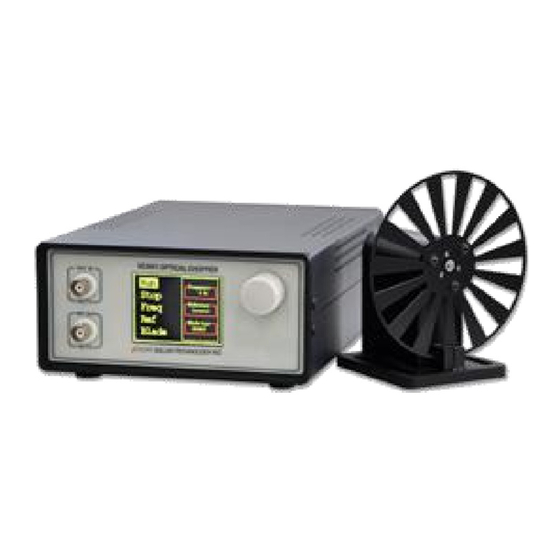
- Page 2 Tel: 886. 909 602 109 Email: sales@salukitec.com www.salukitec.com The document applies to following models: SE3001 Optical Chopper (1 Hz to 10 kHz) Standard package: SE3001 control box SE3001 optical chopping head (1×) 10-slot chopping blade (6×) M3 × 4 Hexagon socket button head screws for blade retention ...
- Page 3 Saluki. Saluki Tech owns the copyright of this document which should not be modified or tampered by any organization or individual or reproduced or transmitted for the purpose of making profit without its prior permission, otherwise Saluki will reserve the right to investigate and affix legal liability of infringement.
-
Page 4: Table Of Contents
Tel: 886. 909 602 109 Email: sales@salukitec.com www.salukitec.com Content 1 Overview................................. 5 1.1 LCD Display..............................5 1.2 Chopping Head..............................6 1.3 Front Panel and Rear Panel..........................7 2 Install Instructions..............................8 3 Basic Operation............................... 9 3.1 Internal Reference Mode...........................9 3.2 External Reference Mode..........................9 3.3 Reference-Out Signal............................9 4 Detailed Operations............................... -
Page 5: Overview
20 Hz to 1000 Hz. Other available blades include 2 slots, 6 slots, 15 slots, 30 slots, 60 slots, 100 slots and 5/7 slots. 1.1 LCD Display Fig.2 LCD Display The main menu of SE3001 is shown in Fig.2. There are five function settings, including [Run], [Stop], [Freq], [Ref] and [Blade]. -
Page 6: Chopping Head
1.2 Chopping Head The SE3001 chopping head is made of five parts: a base, a stand, a blade hub, a photoelectric door and a cable connector as Fig.3. The blade hub is used to fix the blade to the chopping head. The photoelectric door measures the spin frequency of the blade. -
Page 7: Front Panel And Rear Panel
Tel: 886. 909 602 109 Email: sales@salukitec.com www.salukitec.com 1.3 Front Panel and Rear Panel Fig.4 Front panel Fig.5 Rear panel... -
Page 8: Install Instructions
4. Mount the SE3001 Control Box and the SE3001 Optical Chopping Head on a stable surface. Attach the power supply line cord to the SE3001 and plug into an AC outlet. Turn the power switch on and then you can use it. -
Page 9: Basic Operation
1. Turn the SE3001 power on. The LCD display shows the logo and enters the main menu. By turning the front panel control knob, different menu items can be highlighted. Push the control knob to select the highlighted item. -
Page 10: Detailed Operations
SE3001 control box. The SE3001 control box uses two timers T1 and T2 to measure the frequency of the feedback signal. The T1 timer is triggered by the rising or falling edge of the signal. -
Page 11: Frequency Display
4.4 Frequency Display The SE3001 uses a 320×240 LCD color display to show its menu and data. If the internal reference mode is used, the display will show the internal reference frequency set by users. If the external reference mode is used, the... -
Page 12: Remote Communications
Tel: 886. 909 602 109 Email: sales@salukitec.com www.salukitec.com 5 Remote Communications Users can use PC to control SE3001 by commands through USB port. Detailed steps to run a remote communication is as below: 5.1 Installing the UART to USB Drivers Open the disk and the files inside are as below: Fig.6 CD-ROM files... -
Page 13: Installing The Software Drivers
1. If the PC is online, the PC will search a proper driver and install it online automatically when the PC is connected with the SE3001 through USB. 2. If the PC has installed the “FT232_driver.exe”, you can skip this step. -
Page 14: Installing Software
5.4.1 Connection between PC and SE3001 Before using the software to configure the SE3001, users should connect the PC and the SE3001 successfully. 1. Choose the right COM port at “COM configuration”, and then click “Connect” as Fig.12. If the connection... - Page 15 Tel: 886. 909 602 109 Email: sales@salukitec.com www.salukitec.com Fig.12 Connection steps diagram 2. If the connection fails as Fig.13, please check whether the COM port is correct and then refresh and re-connect Fig.13 Connection error Note that: users can search the COM port at “My Computer/Property/Device Manager/COM and LPT”. 5.4.2 Parameters configuration 1.
-
Page 16: Command Syntax
SE3001 allows users to query the current value of internal parameters through commands. A query is formed by appending a question mark "?" to the command mnemonic and omitting the desired parameter(s) from the command. - Page 17 Note that this software can set the communication mode, the receiver mode, the transfer mode. The default Baud rate of the SE3001 is 921600. The SE3001 has no parity bit, 8 data bits and 1 stop bit. Choose “Fixed Byte Checksum” in appendix bits setting as is shown in Fig.16. The value of the fixed byte is 0DH.
- Page 18 (a) The commands obey the rules described on Chapter 5.5. The real case is shown in Fig.18. Enter commands and then click “Send”. Then the SE3001 will execute the received commands. If the commands query returns, the returned result will be shown in data receive region.
- Page 19 Tel: 886. 909 602 109 Email: sales@salukitec.com www.salukitec.com returns the value Input command, then press send. Send and receive bytes Fig.18 Operation example (b) Multiple commands are separated by semicolons “;”, such as “*IDN?;FREQ=123;*STAR;REFE?;FREQ?; *IDN?” as Fig.19.
- Page 20 Tel: 886. 909 602 109 Email: sales@salukitec.com www.salukitec.com After the instruction is executed, the value is returned in turn. The instructions are separated by ";" Fig.19 The execution of multiple instructions (c) If users want to execute some commands repeatedly, set “Data Flow Cycle Transfer” on. i.
- Page 21 Fig.20 Read the chopping frequency continuously Note that the LCD display will refresh the SE3001 state at the same time when the PC uses “UartAssist.exe” to control the SE3001. The SE3001 can use many other kinds of UART assistant software. All the steps are basically...
-
Page 22: Maintenance And Troubleshooting
6 Maintenance and Troubleshooting 6.1 Maintenance 1. The high-precision DC motor used in SE3001 should be turned off to extend its service life when the SE3001 is not used. 2. Do not touch the spinning blade by hands or other things. Otherwise, the blade will be damaged and deformed. -
Page 23: Menu Overview
Tel: 886. 909 602 109 Email: sales@salukitec.com www.salukitec.com 7 Menu Overview Starts the blade spinning Stops the blade spinning Sets the frequency Selects internal mode Selects external mode Selects the blade Selects the blade you used type... -
Page 24: Drawings
Tel: 886. 909 602 109 Email: sales@salukitec.com www.salukitec.com 8 Drawings 8.11" 150.0 OPTICAL CHOPPER 2.76" Fig.21 Chopper main chassis dimensions... - Page 25 Tel: 886. 909 602 109 Email: sales@salukitec.com www.salukitec.com Fig.22 Chopper mechanical dimensions Note that the unit is in millimeter. --END OF DOCUMENT--...