Sign In
Upload
Download
Table of Contents
Contents
Add to my manuals
Delete from my manuals
Share
URL of this page:
HTML Link:
Bookmark this page
Add
Manual will be automatically added to "My Manuals"
Print this page
×
Bookmark added
×
Added to my manuals
Manuals
Brands
Saluki Manuals
Measuring Instruments
S3101 Series
Quick start manual
Saluki S3101 Series Quick Start Manual
Cable & antenna analyzer
Hide thumbs
Also See for S3101 Series
:
User manual
(76 pages)
1
2
3
4
5
Table Of Contents
6
7
8
9
10
11
12
13
14
15
16
17
18
19
20
21
22
23
24
25
26
27
28
29
30
page
of
30
Go
/
30
Contents
Table of Contents
Bookmarks
Table of Contents
Table of Contents
1 Overview
2 Ready to Use
Pre-Operation Preparation
Environmental Requirements
Power Supply Requirements
Electro-Static Discharge (ESD)
Startup and Utilization
Front Panel
Operating Interface
Top Interface
Power Interface
Digital Interface
Test Port
Instrument Symbol
Battery
Turn On/Off
3 Typical Application
Calibration
Cable Test
Return Loss/Vswr Measurement
Cable Loss Measurement
DTF Measurement
Antenna Test
Universal Devices and Parts Test
Test Skills
4 Getting Help
Basic Check
Help Information
Repair Method
Advertisement
Quick Links
Download this manual
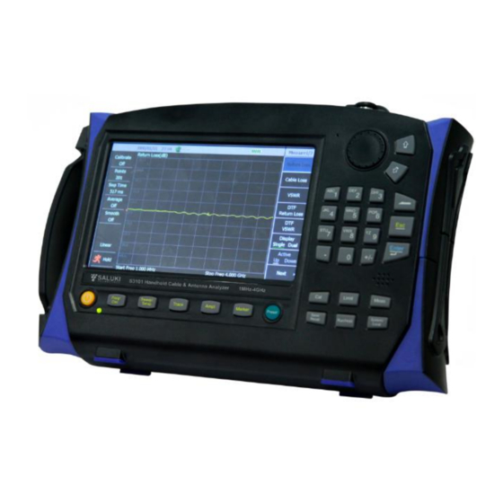
S3101 Cable & Antenna Analyzer
Quick Start Guide
Saluki Technology Inc.
Table of
Contents
Previous
Page
Next
Page
1
2
3
4
5
Advertisement
Table of Contents
Need help?
Do you have a question about the S3101 Series and is the answer not in the manual?
Ask a question
Questions and answers
Related Manuals for Saluki S3101 Series
Measuring Instruments Saluki S3101 User Manual
Cable & antenna analyzer (76 pages)
Measuring Instruments Saluki S3602 Series User Manual
Vector network analyzer (312 pages)
Measuring Instruments Saluki S3602 Series Quick Start Manual
Vector network analyzer (69 pages)
Measuring Instruments Saluki S3531 series User Manual
Spectrum analyzer (71 pages)
Measuring Instruments Saluki S3331 Series Quick Start Manual
Handheld spectrum analyzer (26 pages)
Measuring Instruments Saluki S3331B User Manual
S3331 series. handheld spectrum analyzer (60 pages)
Measuring Instruments Saluki S3331 Series Programming Manual
Handheld spectrum analyzer (47 pages)
Measuring Instruments Saluki S3302 Series Quick Start Manual
Spectrum analyzer (34 pages)
Measuring Instruments Saluki S3302SB User Manual
Handheld spectrum analyzer (199 pages)
Measuring Instruments Saluki S3302E Maintenance Manual
Spectrum analyzer (25 pages)
Measuring Instruments Saluki S3101A Quick Start Manual
Cable & antenna analyzer (30 pages)
Measuring Instruments Saluki S3532 Series User Manual
Spectrum analyzer (121 pages)
Measuring Instruments Saluki S2106 Series User Manual
Optical time domain reflectometer (60 pages)
Measuring Instruments Saluki S5105 Series User Manual
Microwave multifunctional analyzer (204 pages)
Measuring Instruments Saluki S5800E Series User Manual
Field comm analyzer (173 pages)
Measuring Instruments Saluki STB8827 Series Operation Manual
(131 pages)
This manual is also suitable for:
S3101a
S3101b
Table of Contents
Print
Rename the bookmark
Delete bookmark?
Delete from my manuals?
Login
Sign In
OR
Sign in with Facebook
Sign in with Google
Upload manual
Upload from disk
Upload from URL


Need help?
Do you have a question about the S3101 Series and is the answer not in the manual?
Questions and answers