Download Print this page
TE Connectivity CERTI- CRIMP Series Instruction Sheet

TE Connectivity CERTI- CRIMP Series Instruction Sheet

Hand crimping tools
Hide thumbs Also See for CERTI- CRIMP Series:

Advertisement

Quick Links

PROPER USE GUIDELINES
Cumulative Trauma Disorders can result from the prolonged use of manually powered hand tools. Hand tools are intended for occasional use and low volume
applications. A wide selection of powered application equipment for extended- - use, production operations is available.
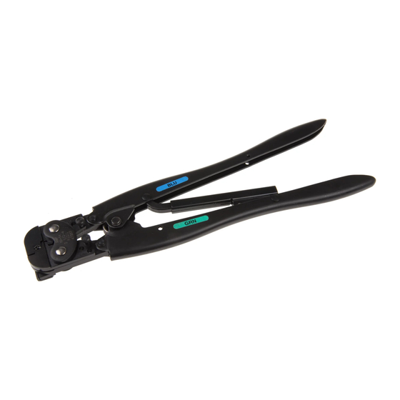
Label (Color Coded for PIDG*
and PLASTI- - GRIP* Products)
Wire Size Range
Stamped Here
Locator
Jaws
1. INTRODUCTION
CERTI--CRIMP hand crimping tools listed in Figure 1
are used to crimp the products onto the wire listed in
Figure 2.
Dimensions in this instruction sheet are in
NOTE
millimeters [with inches in brackets]. Figures and
i
illustrations are for reference only and are not
drawn to scale.
Reasons for reissue of this instruction sheet are
provided in Section 7, REVISION SUMMARY.
2. DESCRIPTION
(Figure 1)
The handles and label (if applicable) of each tool are
color--coded to match the color coding of the product
to be crimped. The tools may show more than one
color code.
For example, Tool 47386 can be used to apply
NOTE
PIDG terminals and splices with a yellow color
i
code as well as spare wire caps with a red color
code.
E2011 Tyco Electronics Corporation, a TE Connectivity Ltd. Company
All Rights Reserved
TE logo is a trademark.
*Trademark. Other product names, logos, or company names might be trademarks of their respective owners.
CERTI- CRIMP*
Hand Crimping Tools
Handles
Label (Color Coded
for Sealed Splices)
Insulation Crimp Adjustment Pins
(Shown in Position 3)
Figure 1
TOOLING ASSISTANCE CENTER 1--800--722--1111
PRODUCT INFORMATION 1--800--522--6752
Ratchet
PRODUCT
PIDG Terminals and Splices
PIDG Radiation Resistant
Terminals and Splices
PLASTI--GRIP Butt Splices
PIDG Insulation Restricting
Nylon Terminals
PIDG FASTON* Receptacles
641321--1 (.187 Series) and
641324--1 (.110 Series)
PLASTI--GRIP Terminals
Spare Wire Cap
Figure 2
This controlled document is subject to change.
For latest revision and Regional Customer Service,
visit our website at www.te.com
Instruction Sheet
408- - 1559
10 Mar 11 Rev T
Hand Crimping Tool
Part Numbers
46121
47304
47386
47386- - 5
47387
47907- - 1
48518- - 2
68343- - 1
69151- - 1
69454
169485
COPPER WIRE
SIZE RANGE
TYPE
(AWG)
Solid or
30--14
Stranded
Stranded
27--14
Solid or
26--22
Stranded
Stranded
26--14
Stranded
26--24
Solid or
22--14
Stranded
Stranded
22--14
1 of 10
LOC B

Advertisement

loading

Summary of Contents for TE Connectivity CERTI- CRIMP Series

  • Page 1 Figure 2 code. 1 of 10 E2011 Tyco Electronics Corporation, a TE Connectivity Ltd. Company TOOLING ASSISTANCE CENTER 1--800--722--1111 This controlled document is subject to change. All Rights Reserved...
  • Page 2: Crimping Procedure

    408- 1559 These tools are members of the CERTI--CRIMP hand embossed on a crimped product when it is crimped crimping tool family. The ratchet ensures full crimping using the correct tooling. of the product. Once engaged, the ratchet will not 3.1.
  • Page 3 408- 1559 TOOL PRODUCT WIRE SIZE STRIP LENGTH PART PART INSULATION INSULATION INSULATION INSULATION COLOR COLOR DESCRIPTION DESCRIPTION RANGE RANGE NUMBER CODE COLOR DIA RANGE TERMINAL SPLICE (AWG) 1.04--2.62 Blue 16--14 [.041- - .103] PIDG Terminals and Splices a s a d Sp ces PLASTI--GRIP Terminals 20--16 0.41--1.65...
  • Page 4 408- 1559 PIDG PIDG Insulation PIDG Butt PLASTI- GRIP Terminal Restricting Terminal Splice Butt Splice Window Window Indent Indent Wire Wire PIDG FASTON PLASTI- GRIP Stop Stop Receptacle Terminal Wire “B” Equals Wire Barrel “C” Equals Insulation Barrel Stop First Crimp Insulation Crimp Adjustment Locator Seats in Pins in Position 3...
  • Page 5 408- 1559 7. Hold the wire in position, and complete the 9. Inspect crimped product according to Figure 7. crimp by closing the tool handles until the ratchet Product not meeting these conditions should NOT releases. be used. 8. Release the tool handles, allow the handles to open fully, and remove the crimped spare wire cap.
  • Page 6: Maintenance And Inspection

    408- 1559 4. INSULATION CRIMP ADJUSTMENT 5. MAINTENANCE AND INSPECTION Hand crimping tools are inspected before shipment. The insulation crimp section of the hand tool has The tool received should be inspected immediately three positions: 1 (tight), 2 (medium), and 3 (loose) to upon arrival to ensure that the tool has not been adjust the wire insulation crimp grip.
  • Page 7 408- 1559 B. Gaging Crimping Chamber 4. Repeat the gage inspection for the insulation crimp section of the crimping chamber, making This inspection requires the use of plug gages sure to use the correct plug gage. conforming to the dimensions listed in Figure 8. To gage the crimping chamber, proceed as follows: If the crimping chamber conforms to the gage inspection, the tool is considered dimensionally...
  • Page 8 408- 1559 Suggested Plug Gage Design — Insulation Barrel Crimp Section G (GO) G (NO- - GO) Jaw Closure Configuration W (Max) 6.35 [.250] Typ JAW CLOSURE{ DIMENSION F GAGE ELEMENT{{ DIMENSION G DIMENSION (Adjustment Pins in Position 1) TOOL TOOL W (Width) W (Width)
  • Page 9: Revision Summary

    408- 1559 2. Position the product in the crimping chamber A complete inventory should be stocked and according to Paragraph 3.1, Steps 1 through 5 or controlled to prevent lost time when replacement of Paragraph 3.2, Steps 1 through 6. parts is necessary.
  • Page 10 408- 1559 Tool 47304 Only 76.2 [3.00] Approx 22.22 [.875] 279.4 [11.0] Approx PART NUMBER FOR TOOL ITEM DESCRIPTION 47387 & 46121 47304 47386 47386- - 5 68343- - 1 RING, Retaining 21045--3 21045--3 21045--3 21045--3 21045--3 PIN, Retaining 1--23619--6 1--23619--6 1--23619--6 1--23619--6...