Kessel Pumpfix F Instructions For Installation, Operation And Maintenance
Backwater pumping station
Hide thumbs
Also See for Pumpfix F:
- Installation and operating manual (72 pages) ,
- Installation and operating instructions manual (96 pages)
Table of Contents
Advertisement
Available languages
Available languages
Quick Links
ANLEITUNG FÜR EINBAU, BEDIENUNG UND WARTUNG
KESSEL Rückstaupumpanlage
Pumpfix F
Installation
Inbetriebnahme
der Anlage wurde durchgeführt von Ihrem Fachbetrieb:
Name/Unterschrift
Stand 2019/12
Pumpfix F
Einbau in die
Bodenplatte
Pumpfix F
freiliegend
Einweisung
Datum
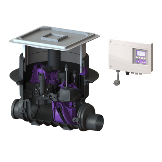
Produktvorteile
Für fäkalienhaltiges und
fäkalienfreies Abwasser
Rückstauverschluss und
Entwässerungspumpe
Steckerfertiges Schaltgerät mit
Display und Selbstdiagnosesystem
(SDS) inkl. integrierter
Batteriepufferung
Motorische Verriegelung der
Rückstauklappe
Integrierte Ablauffunktion zur
Oberflächenentwässerung
Ort
Stempel Fachbetrieb
D Seite
1
GB Page
26
F
Page
51
I
Pagina 77
NL Pagina 103
PL Strona 128
85101 Lenting
Z-53.2-388
Sach-Nr. 010-843
Advertisement
Chapters
Table of Contents

Related Manuals for Kessel Pumpfix F


Summary of Contents for Kessel Pumpfix F
- Page 1 ANLEITUNG FÜR EINBAU, BEDIENUNG UND WARTUNG KESSEL Rückstaupumpanlage D Seite GB Page Pumpfix F Page Pagina 77 NL Pagina 103 PL Strona 128 Produktvorteile Für fäkalienhaltiges und fäkalienfreies Abwasser Rückstauverschluss und Entwässerungspumpe Steckerfertiges Schaltgerät mit Display und Selbstdiagnosesystem (SDS) inkl. integrierter...
-
Page 2: Table Of Contents
Allgemeine Hinweise für die Wartung .......................19 Wartungsintervalle ..............................19 Wartung vorbereiten ..............................19 Komponenten demontieren ..........................20 Komponenten reinigen ............................21 Komponenten mit Dichtungen einfetten ......................21 Komponenten zusammenbauen .........................21 Technische Daten Pumpen ..................................22 Schaltgerät Pumpfix F .............................22 Förderstrom .................................23 DOP/Leistungserklärung 2 / 152 2019/12 010-843... -
Page 3: Einleitung
Als Niveauerkennung wird eine optische Sonde verwendet. Ist das entsprechende Niveau erreicht, wird das Abpumpen über den Grundkörper des Pumpfix F, gegen den anstehenden Rückstau, aktiviert. Bei Netzausfall kann über einen Zeitraum von ca. 2 Stunden mittels Batteriebetrieb die Funktionssicherheit der motorbetriebenen Rückstauklappe sichergestellt werden. -
Page 4: Allgemeine Hinweise Zu Dieser Betriebs- Und Wartungsanleitung
Einleitung Allgemeine Hinweise zu dieser Betriebs- und Wartungsanleitung Diese Betriebs- und Wartungsanleitung ist nur in Verbindung der Betriebs- und Montageanleitung des Pumpfix F Schaltgeräts (Sach-Nr. 016-004) vollständig. Verwendete Symbole und Legenden <1> Hinweis im Text auf eine Legendennummer in einer Abbildung Bezug auf eine Abbildung •... -
Page 5: Typenschild
Einleitung 1.3.2 Funktionsprinzip Pumpfix F freiliegend Abb. [2] Rückstauebene Typenschild Informationen auf dem Typenschild Bezeichnung der Anlage Materialnummer Anschlussspannung und Anschlussfrequenz Pumpfix F Comfort Hydraulische Daten xxxxx U = xxxV xxHz I = x,xA P1 = x,xkW Allgemeine Daten Q = xxm³/h... -
Page 6: Lieferumfang
Einleitung Lieferumfang Anlage bzw. alle Lieferkomponenten auf Vollständigkeit und evtl. Mängel überprüfen. 1.5.1 Variante Pumpfix F zum Einbau in die Bodenplatte Grundkörper Aufsatzstück, mit Zulaufdeckel Verlängerungsstück (optional, max. 2 Stück) Pumpeneinheit Motorische Klappeneinheit Dichtung Kabeldurchführung Zulauf-Seite Auslauf-Seite Elektropack (E-Pack) Abb. [4] 1.5.2... -
Page 7: Sicherheit
Sicherheit Sicherheit Bestimmungsgemäße Verwendung Die Rückstaupumpanlage dient als Entwässerungsanlage für fäkalienhaltiges und –freies, häusliches und gewerbliches Abwasser. Personalauswahl und -qualifikation Personen, die die Rückstaupumpanlage montieren, müssen mindestens 18 Jahre alt sein. – für die jeweiligen Tätigkeiten ausreichend geschult und qualifiziert sein. –... - Page 8 Sicherheit 2.4.4 Gefahr für die Gesundheit Die Rückstaupumpanlage fördert fäkalienhaltiges Abwasser, das gesundheitsgefährdende Stoffe enthalten kann. Es ist sicherzustellen, dass kein direkter Kontakt zwischen dem Abwasser oder davon verschmutzten Anlagenteilen mit Augen, Mund oder Haut stattfindet. Bei einem direkten Kontakt die betroffene Körperstelle sofort gründlich reinigen und ggf.
-
Page 9: Montage
Montage Montage Allgemeines zur Montage Die Rückstaupumpanlage wird, entsprechend den auf einer Baustelle üblichen Bauabschnitten, zu unterschiedlichen Zeitpunkten montiert und in Betrieb genommen. 3.1.1 Baugruppenübersicht Pumpfix F Einbau in die Bodenplatte Geruchsverschluss Pumpeneinheit Alarmsonde Rückstauklappe Rückstausonde Motorische Klappeneinheit Abb. [6]... - Page 10 Montage 3.1.2 Baugruppenübersicht Pumpfix F freiliegend Pumpeneinheit Alarmsonde Rückstauklappe Motorische Klappeneinheit Rückstausonde Abb. [7] 10 / 152 2019/12 010-843...
-
Page 11: Einbauvorschlag „Schwarze Wanne
Montage Einbauvorschlag „Schwarze Wanne“ BWS* Schematische Darstellung Abb. [8] 1 Pumpfix F 2 Dichtungsset Art.-Nr. 83 073: Verlängerungsstück mit Flansch und Gegenflansch (für den Anschluss an eine bauseitige Dichtbahn) 3 Verlängerungsstück Art.-Nr. 83 070 a Fliesen f Schutzbeton b Estrich g Schaltgerät... -
Page 12: Einbauvorschlag „Weiße Wanne
- Ausreichend Abstand zur Wand bzw. Objekten für Wartungsarbeiten einhalten. - Beruhigungsstrecke vor und nach dem Pumpfix F (min. 1 m) einhalten. - Kabelleerrohr (DN70) vom Pumpfix F zum Montageort des Schaltgeräts verlegen. Richtungsänderungen nur mit 45°-Bögen vornehmen. Bei der Auswahl des Montageorts die Position für das Schaltgerät berücksichtigen: Die Kabellänge der Elektrokomponenten beträgt 5 Meter (Verlängerungssets sind optional erhältlich). -
Page 13: Grundkörper Montieren
Grundkörper montieren - Die beiden Stutzen Zulauf- <56> und Auslaufseite <57> mit dem Grundkörper <1> verbinden, die Schnellverschlüsse <64> am Grundkörper ermöglichen eine rasche Montage. - Den Pumpfix F mit dem Rohrleitungssystem verbinden. Abb. [10] Abb. [11] Einbau in freiliegende Abwasserleitung Einbau in die Bodenplatte Abb. -
Page 14: Grundkörper Waagerecht Ausrichten
Montage Grundkörper waagerecht ausrichten Abb. [14] Einbau in die Bodenplatte (schwarze Wanne) Bauseitige Dichtungsbahn <68> zwischen Pressdichtungsflansch <13> und Gegenflansch <47> einklemmen und mit den Schrauben <48> verschrauben. Abb. [15] 14 / 152 2019/12 010-843... -
Page 15: Einbau In Die Bodenplatte (Weiße Wanne)
Montage Einbau in die Bodenplatte (weiße Wanne) Dichtung <37> in Grundkörper <1> einlegen und auf Sitz der Dichtung achten. Anschließend Oberseite der Dichtung fetten. Verlängerungsstück mittiger Flansch <33> einschieben und in Position bringen. Abb. [16] Entlüftung sicherstellen Bei freiliegendem Einbau sicherstellen, dass das vormontierte Entlüftungsventil inkl. -
Page 16: Kabelleerrohr Montieren
(DN50) an den Grundkörper heranführen und montieren. Für Richtungsänderungen max. 45° Bögen verwenden. Sollte das Kabelleerrohr im Aufsatzstück installiert werden, muss dieses mit der KESSEL Sägeglocke Art.-Nr. 500101 oder einer handelsüblichen Sägeglocke Ø 60 mm und der Rohrdurchführungsdichtung Art.-Nr. 850114 ausgeführt werden. -
Page 17: Abdeckplatte Montieren
Montage 3.12 Abdeckplatte montieren Die Montage erfolgt zum Schutz vor Verunreinigungen durch z.B. Baumaterial. Dabei: - Dichtung von unten auf Abdeckplatte montieren - Dichtungsbereich sauber halten - Dichtung außen einfetten • Abdeckplatte <51> in das Aufsatzstück <3> einsetzen. • Beide Deckelverschlüsse <78> schließen. Abb. -
Page 18: Funktionsprüfung/Inbetriebnahme
Funktionsprüfung/Inbetriebnahme Funktionsprüfung/Inbetriebnahme Vor der Inbetriebnahme muss eine Funktionsprüfung aller elektrischen Komponenten durchgeführt werden. Funktionsprüfung Rückstau 1. Prüfen, ob alle elektrischen Anschlüsse ordnungsgemäß ausgeführt wurden, Stromverbindung herstellen. 2. Rückstausonde demontieren und in Wasserglas eintauchen. 3. Prüfen, ob Rückstauklappe zufährt. (Motorengeräusch, Hebel legt sich selbsttätig um). 4. -
Page 19: Wartung
Wartung Wartung Vor einem Öffnen von Gehäuseabdeckungen, Steckern und Kabeln (auch an den potentialfreien Kontakten) sind diese spannungsfrei zu machen. Arbeiten an elektrischen Bauteilen dürfen nur von Fachpersonal (siehe 2.2) durchgeführt werden. Allgemeine Hinweise für die Wartung Gefahr durch giftige und gesundheitsgefährdende Dämpfe, Gase und Stoffe (z. B. Bakterien, Viren). Befindet sich die Rückstaupumpanlage in einem Schacht, sind darin notwendige Arbeiten ausschließlich durch Fachpersonal (siehe 2.2) durchzuführen. -
Page 20: Komponenten Demontieren
Wartung Komponenten demontieren Pumpe demontieren • Beide Schnellverschlüsse öffnen. • Einhandverschluss am Klappengehäuse öffnen. • Schwenkanschluss öffnen. • Pumpe kann werkzeuglos herausgehoben werden. Abb. [23] Niveauerfassung demontieren • Beide Schrauben (TX25) herausschrauben. • Sonde mit Halterung herausziehen. •... -
Page 21: Komponenten Reinigen
Wartung Pumpe überprüfen, reinigen, ggf. warten • Ansaugkorb mit Schneidwerk demontieren (TX 20). • Welle hinter Laufrad auf Fremdkörper prüfen, ggf. reinigen. • Entlüftungsöffnung freimachen. • Schneidmesser auf Welle und Schneidplatte im Spiralgehäuse auf Verschleiß überprüfen und ggf. austauschen (siehe Zubehörset 28075, dem Zubehörset beiliegende Anleitung EBA-Nr. -
Page 22: Technische Daten
Phoenix-Stecker Anschlusskabel** 5 m, 3x1 mm² Erforderliche Absicherung Siehe Anleitung Schaltgerät Betriebsart S3 - 50% Schaltgerät Pumpfix F Betriebsspannung VAC / 50Hz Leistung Standby, W Leistung, W 1200 Potentialfreier Kontakt (Option), Umschaltkontakt V DC / A 42 / 0,5 Einsatztemperatur, °C 0°... -
Page 23: Förderstrom
Technische Daten Förderstrom Werte für SPZ 1000 mit Schneidrad Max. Förderm Q (m 10,0 10,9 Max. Förderm Q (l/sec.) Förderhöhe H (mWS) H [ m ] Q [ m /h ] Abb. [28] 2019/12 23 / 152 010-843... -
Page 24: Dop/Leistungserklärung
Sicherheit und BarrierefreiheiUsafety and accessibility/securite et accessibilite 100 % recyclingfähig/ Nachhaltige Nutzung/sustainable use/utilisation durable recyclable/recyclable 1'i0\- Lenting, den 20. Mai 2016 E. Thiemt (Vorstand Technik KESSEL AG) R. Priller (Dokumentenverantwortlicher) Managing Board Responsible for Documentation Conseil d · administration Responsable de la documentation... - Page 25 DOP/Leistungserklärung 2019/12 25 / 152 010-843...
- Page 26 INSTRUCTIONS FOR INSTALLATION, OPERATION AND MAINTENANCE KESSEL Backwater Pumping Station Pumpfix F Product advantages For wastewater with and without sewage Backwater valve and draining pump Plug & play control unit with display and self-diagnosis system (SDS) ncl. integrated battery back-up...
- Page 27 Prepare maintenance ...............................44 Remove the components ............................45 Clean the components ............................46 Grease the components with seals ........................46 Assemble the components ............................46 Technical data Pumps ....................................47 Control unit Pumpfix F .............................47 Pumping flow ................................48 DoP/ Declaration of Performance 2019/12 27 / 152 010-843...
-
Page 28: Introduction
Bahnhofstraße 31 85101 Lenting, Germany Our qualified local service partners will be happy to help with any technical problems you may have. Visit www.kessel.de/ kundendienst to find your contact. If necessary, our Factory Customer Service provides support with services such as commissioning, maintenance or general inspection throughout the DACH region, other countries on request. -
Page 29: General Instructions On Using These Operating And Maintenance Instructions
Introduction General instructions on using these operating and maintenance instructions These operating and maintenance instructions are only complete in combination with the operating and maintenance instructions of the Pumpfix F control unit (part no. 016-004). Symbols and legends used <1>... -
Page 30: Type Plate
Introduction 1.3.2 How the Pumpfix F for exposed installation works Fig. [2] Backwater level Type plate Information on the typeplate Name of the system Material number Connection voltage and connection frequency Pumpfix F Comfort Hydraulic data xxxxx General data U = xxxV... -
Page 31: Scope Of Delivery
Introduction Scope of delivery Check the system and all components supplied for completeness and for any faults 1.5.1 Variant Pumpfix F for underground installation Drain body Upper section, with inflow cover Extension section (optional, max. 2 units) Pump unit Motor-driven flap unit... -
Page 32: Safety
Safety Safety Correct use The backwater pumping station serves as a draining system for wastewater with and without sewage, domestic and industrial wastewater. Staff selection and qualification Persons who install the backwater pumping station must – be at least 18 years old. –... - Page 33 Safety 2.4.4 Health risks The backwater pumping station pumps wastewater with sewage which can contain hazardous substances. Make sure eyes, mouth or skin do not come into direct contact with the wastewater or parts of the system soiled by it. In the case of direct contact, the part of the body affected must be washed thoroughly immediately and disinfected if necessary.
-
Page 34: Installation
General points related to installation The backwater pumping station is installed and put into operation at different times according to the usual construction phases on a building site. 3.1.1 Assemblies Pumpfix F for underground installation Odour trap Pump unit Alarm probe... - Page 35 Installation 3.1.2 Assemblies Pumpfix F for exposed installation Pump unit Alarm probe Backwater flap Motor-driven flap unit Backwater probe Fig. [7] 2019/12 35 / 152 010-843...
-
Page 36: Installation Suggestion "Black Tub
Installation suggestion “black tub” Schematic illustration BWS* Fig. [8] 1 Pumpfix F 2 Sealing gasket set art. # 83 073: extension section with flange and counterflange (for connection to an on-site sealing sheet) 3 Extension Section art. # 83 070 a Tiles... -
Page 37: Installation Suggestion "White Tub
- Maintain a stilling section before and after the Pumpfix F (min. 1 m). - Route a cable conduit (DN70) from the Pumpfix F to where the control unit is installed. Changes of direction must be made using 45° bends only. -
Page 38: Installing The Drain Body
- Connect the two muffs on the inflow <56> and outflow side <57> to the drain body <1>, the quick-release closures <64> on the drain body make fast installation possible. - Connect the Pumpfix F to the pipe system. Fig. [11] Fig. [10]... -
Page 39: Aligning The Drain Body Horizontally
Installation Aligning the drain body horizontally Fig. [14] Underground installation (black tub) Clamp the on-site sealing sheet <68> between the pressure sealing flange <13> and the counterflange <47> and screw together using the screws <48>. Fig. [15] 2019/12 39 / 152 010-843... -
Page 40: Underground Installation (White Tub)
Installation Underground installation (white tub) Insert the sealing gasket <37> in the drain body <1> and make sure the sealing gasket is in place correctly. Then grease the upper side of the sealing gasket. Push the extension section central flange <33> in and move it into position. -
Page 41: Installing The Cable Conduit
For changes of direction use max. 45° bends. If the cable conduit has to be installed in the upper section, drill a hole with the KESSEL hole saw (art. # 500101) or a standard Ø 60 mm hole saw and put in the pipe sealing gasket (art. -
Page 42: Installing The Inflow Cover
Installation 3.12 Installing the inflow cover This is fitted to protect the drain from soiling through e.g. construction material. For this: - Fit the seal to the cover plate from below - Keep the sealing area clean - Grease the outside of the sealing gasket •... -
Page 43: Functional Check/ Commissioning
Functional check/ commissioning Functional check/ commissioning Before commissioning, a functional check must be carried out on all electrical components. Functional check backwater 1. Check whether all electrical connections have been executed correctly, establish power connection. 2. Remove backwater probe and submerse it in a water glass. 3. -
Page 44: Maintenance
Maintenance Maintenance Before housing covers, plugs and cables (including those on potential-free contacts) are opened they must be switched voltage-free. Work on electrical components may only be carried out by specialist staff (see 2.2). General maintenance information Risk caused by toxic and hazardous vapours, gases and substances (e. g. bacteria, viruses). If the backwater pumping station is located in an inspection chamber, any necessary work must always be done by specialist staff (see 2.2). -
Page 45: Remove The Components
Maintenance Remove the components Remove the pump • Open both quick-release closures. • Open the one-handed closure on the flap housing. • Open the swivel connection. • The pump can be lifted out without any tools. Fig. [23] Remove the level detection •... -
Page 46: Clean The Components
Maintenance Check the pump, clean and perform maintenance if necessary • Remove the intake cage with macerator (TX 20). • Check the shaft behind the impeller for objects or soiling, clean if necessary. • Clear the ventilation pipe. • Check the cutter blade on the shaft and cutting plate in the spiral housing for wear and replace if necessary (see accessories set 28075 and follow the installation instructions no. -
Page 47: Technical Data
5 m, 3x1 mm² Required fuse protection See control unit instructions Mode of operation S3 - 50% Control unit Pumpfix F Operating voltage VAC / 50Hz Standby capacity, W Capacity, W 1200 Potential-free contact (option), switchover contact V DC / A 42 / 0.5... -
Page 48: Pumping Flow
Technical data Pumping flow Values for SPZ 1000 with macerator Werte für SPZ 1000 mit Schneidrad Max. pumping capacity Max. Förderm Q (m 10,0 10,9 Max. pumping capacity Max. Förderm Q (l/sec.) Max. pumping height Förderhöhe H (mWS) H [ m ] Q [ m /h ] Fig. -
Page 49: Dop/ Declaration Of Performance
Sicherheit und BarrierefreiheiUsafety and accessibility/securite et accessibilite 100 % recyclingfähig/ Nachhaltige Nutzung/sustainable use/utilisation durable recyclable/recyclable 1'i0\- Lenting, den 20. Mai 2016 E. Thiemt (Vorstand Technik KESSEL AG) R. Priller (Dokumentenverantwortlicher) Managing Board Responsible for Documentation Conseil d · administration Responsable de la documentation... - Page 50 Technical data 50 / 152 2019/12 010-843...
- Page 51 INSTRUCTIONS DE MONTAGE, D’UTILISATION ET DE MAIN- TENANCE Clapet anti-retour avec pompe KESSEL Pumpfix F Avantages du produit Pour eaux grises et eaux-vannes Pumpfix F Installation à enterrer Clapet anti-retour et pompe d‘épuisement Gestionnaire « prêt à brancher » avec écran et système d‘autodiagnostic (SDS) avec piles de sauvegarde intégrées...
- Page 52 Introduction Description générale du produit .........................53 Informations d‘ordre général concernant ces instructions d‘utilisation et de maintenance ..54 Principe de fonctionnement ..........................54 Plaque signalétique ..............................55 Fournitures ...................................56 Sécurité Utilisation conforme à l‘usage prévu ........................57 Sélection et qualification du personnel ......................57 Consignes de sécurité organisationnelles ......................57 Risques liés au produit .............................57 Montage Conseils de montage d‘ordre général ........................59...
-
Page 53: Introduction
Une sonde optique sert por la détection de niveau. Le refoulement contre le reflux existant via la pompe (par le corps de base du Pumpfix F) est activé dès l‘atteinte du niveau s‘y rapportant. En cas de panne de secteur, la sécurité de fonctionnement du clapet anti-retour à commande motorisée est assurée pendant env. -
Page 54: Informations D'ordre Général Concernant Ces Instructions D'utilisation Et De Maintenance
Introduction Informations d‘ordre général concernant ces instructions d‘utilisation et de maintenance Ces instructions d‘utilisation et de maintenance ne sont complètes qu‘en combinaison avec les instructions d‘utilisation et de montage du gestionnaire Pumpfix F (Réf. n° 016-004). Pictogrammes et légendes utilisés <1> Information dans le texte attirant l‘attention sur un numéro de légende dans une figure Renvoi à... -
Page 55: Plaque Signalétique
Niveau des plus hautes eaux Plaque signalétique Information sur laplaque signalétique Désignation du poste Numéro du matériau Tension et fréquence d‘alimentation Pumpfix F Comfort Données hydrauliques xxxxx U = xxxV xxHz I = x,xA P1 = x,xkW Données d‘ordre général Q = xxm³/h... -
Page 56: Fournitures
Introduction Fournitures Contrôler le poste et/ou tous les composants livrés quant à l‘intégralité et la présence éventuelle de défauts. 1.5.1 Variante du Pumpfix F à enterrer Corps de base Rehausse, avec couvercle de protection Pièce de rallonge (en option, au plus 2 pièces) Unité... -
Page 57: Sécurité
Sécurité Sécurité Utilisation conforme à l‘usage prévu Le clapet anti-retour avec pompe sert de système d‘assainissement des eaux-vannes, eaux grises et eaux domestiques et industrielles. Sélection et qualification du personnel Les personnes affectées au montage du clapet anti-retour avec pompe doivent –... - Page 58 Sécurité 2.4.4 Risque pour la santé Le clapet anti-retour avec pompe refoule des eaux-vannes susceptibles de contenir des substances nuisibles à la santé. Veiller à exclure tout risque d‘un contact direct entre les eaux usées ou les éléments souillés du poste avec les yeux, la bouche ou la peau.
-
Page 59: Montage
La pose, le montage et la mise en service du clapet anti-retour avec pompe sont effectués le moment donné suivant les tranches de travaux à effectuer habituellement sur le chantier. 3.1.1 Sous-groupes Pumpfix F à enterrer Dispositif anti-odeur Unité de la pompe Sonde d‘alarme... - Page 60 Montage 3.1.2 Sous-groupes Pumpfix F à installer hors sol Unité de pompe Sonde d‘alarme Clapet antiretour Unité motorisée du battant Sonde de reflux Fig. [7] 60 / 152 2019/12 010-843...
-
Page 61: Suggestion De Montage "Cuve Noire
Représentation schématique BWS* Fig. [8] 1 Pumpfix F 2 Jeu de joints d’étanchéité Réf. n° 83 073: Pièce de rallonge avec bride et contre-bride (pour raccordement à une feuille d’étanchéité du maître d’ouvrage) 3 Pièce de rallonge Réf. n° 83 070... -
Page 62: Suggestion De Montage "Cuve Blanche
Montage Suggestion de montage «cuve blanche » Représentation schématique BWS* Fig. [9] 1 Pumpfix F 2 Kit de rallonge avec bride médiane de pose dans du béton étanche, Réf. n° 83075 a Carrelage f Isolation b Étanchéité g Couche de propreté... -
Page 63: Préparatifs De Montage
- prévoir une section d‘apaisement en amont et en aval du Pumpfix F (au moins 1 m). - poser le conduit de câbles (DN de 70) du Pumpfix F jusqu‘à l‘emplacement de montage du gestionnaire. Se servir de coudes d‘au plus 45° pour les changements de direction. -
Page 64: Montage Du Corps De Base
Montage Montage du corps de base - Relier les deux manchons côté entrée <56> et côté sortie <57> avec le corps de base <1>, les fermetures rapides <64> du corps de base permettent un montage rapide. - Relier le Pumpfix F avec le système de conduites,. Fig. -
Page 65: Positionnement Horizontal Du Corps De Base
Montage Positionnement horizontal du corps de base Fig. [14] Installation à enterrer (dans la dalle de fondation (cuve noire)) Serrer la bande d‘étanchéité à prévoir sur site <68> entre la bride de compression <13> et la contre-bride <47> et relier par des vis <48>. -
Page 66: Installation À Enterrer (Dans La Dalle De Fondation (Cuve Blanche))
Montage Installation à enterrer (dans la dalle de fondation (cuve blanche)) Poser le joint d‘étanchéité <37> dans le corps de base <1> et veiller au logement correct du joint d‘étanchéité. Graisser ensuite la face supérieure du joint d‘étanchéité. Glisser la pièce de rallonge dans la bride médiane <33> et l‘amener à... -
Page 67: Montage Du Conduit De Câbles
Se servir de coudes d‘au plus 45° pour les changements de direction. Si le conduit de câbles doit être installé dans la rehausse celui-ci doit être percé avec la scie à cloche KESSEL REF 500501 ou une scie à cloche standard Ø 60 mm et le joint passe câble REF 850114. -
Page 68: Montage Du Couvercle De Protection
Montage 3.12 Montage du couvercle de protection Le montage s‘effectue pour protéger le poste contre les saletés, p. ex. dues aux matériaux de construction. Veiller simultanément : - monter le joint du dessous du couvercle de protection - à la propreté de la zone d‘étanchéité - au graissage extérieur du joint d‘étanchéité... -
Page 69: Contrôle Fonctionnel / Mise En Service
Contrôle fonctionnel / mise en service Contrôle fonctionnel / mise en service Effectuer un contrôle fonctionnel avant de mettre tous les composants électriques en service. Contrôle fonctionnel du reflux 1. Vérifier que tous les raccordements électriques ont été correctement exécutés, les connecter au réseau. 2. -
Page 70: Maintenance
Maintenance Maintenance Débrancher impérativement les fiches d‘alimentation et câbles (y compris au niveau des contacts libres) avant d‘ouvrir les recouvrements ou caches des carters ou boîtiers. Les travaux sur les composants électriques demeurent réservés au domaine de compétence d‘électriciens qualifiés (voir 2.2). Conseils de maintenance d‘ordre général Risque lié... -
Page 71: Démontage Des Composants
Maintenance Démontage des composants Démontage de la pompe • Ouvrir les deux fermetures rapides. • Ouvrir la fermeture manuelle du corps de clapet. • Basculer le raccord pivotant. • Le démontage de la pompe ne nécessite aucun outil. Fig. -
Page 72: Nettoyage Des Composants
Maintenance Vérification, nettoyage et remplacement de la pompe si nécessaire • Démonter la grille d‘aspiration et l‘outil tranchant (TX 20). • Vérifier l‘arbre après démontage de la roue, et nettoyer. • Nettoyer les orifices de ventilation. • Vérifier l’absence d’usure sur le couteau fixe et le couteau mobile dans la volute de pompe, remplacer si nécessaire (voir le kit d’accessoires 28075, observer les instructions de pose et d’utilisation n°... -
Page 73: Caractéristiques Techniques
Caractéristiques techniques Caractéristiques techniques Pompes Pompe SPZ 1000 Poids [kg]* 10,5 Puissance P1 [kW] Puissance P2 [kW] Régime [tr/min] 2800 Tension de service [V] 50 Hz Courant nominal [A] Capacité de refoulement maximum [m³/h] Hauteur de relevage maximum [m] Température du fluide refoulé maximum [°C] Type de protection IP68 (si 3 m/colonne d‘eau maximum... -
Page 74: Débit De Refoulement
Caractéristiques techniques Débit de refoulement Valeurs pour SPZ 1000 avec roue porte-lame Werte für SPZ 1000 mit Schneidrad Max. débit réfoulé Max. Förderm Q (m 10,0 10,9 Max. débit réfoulé Max. Förderm Q (l/sec.) Max. hauteur de Förderhöhe H (mWS) refoulement H [ m ] Q [ m... -
Page 75: Déclaration De Performance
Sicherheit und BarrierefreiheiUsafety and accessibility/securite et accessibilite 100 % recyclingfähig/ Nachhaltige Nutzung/sustainable use/utilisation durable recyclable/recyclable 1'i0\- Lenting, den 20. Mai 2016 E. Thiemt (Vorstand Technik KESSEL AG) R. Priller (Dokumentenverantwortlicher) Managing Board Responsible for Documentation Conseil d · administration Responsable de la documentation... - Page 76 Caractéristiques techniques 76 / 152 2019/12 010-843...
- Page 77 ISTRUZIONI PER L’INSTALLAZIONE, L’USO E LA MANUTENZIONE Sistema di pompaggio antiriflusso KESSEL Pumpfix F Vantaggi del prodotto Per acque nere e acque grigie Valvola antiriflusso e pompa di drenaggio Quadro elettrico pronto per la connessione con display e sistema di auto-diagnostica (SDS), include...
- Page 78 Smontaggio dei componenti ..........................97 Pulizia dei componenti ............................98 Ingrassaggio dei componenti con le guarnizioni ..................98 Assemblaggio dei componenti ..........................98 Dati tecnici Pompe ...................................99 Quadro elettrico Pumpfix F ...........................99 Portata ...................................100 DoP / Dichiarazione di prestazione 78 / 152 2019/12 010-843...
-
Page 79: Introduzione
Introduzione Cara cliente, caro cliente, in qualità di produttore premium di prodotti innovativi per la tecnica di drenaggio, KESSEL offre soluzioni di sistema integrate e un servizio orientato al cliente. Puntiamo sui massimi standard qualitativi e ci impegniamo coerentemente per la sostenibilità – non ci impegniamo solo nella produzione dei nostri prodotti, ma anche rispetto al funzionamento a lungo termine, in modo che la vostra proprietà... -
Page 80: Indicazioni Generali Sulle Presenti Istruzioni Per L'uso E La Manutenzione
Avvertenza: avvertenza tecnica che richiede particolare attenzione. Principio di funzionamento 1.3.1 Principio di funzionamento di Pumpfix F per l‘installazione nel pavimentazione Fig. [1] Livello di riflusso 80 / 152... -
Page 81: Targhetta
Introduzione 1.3.2 Principio di funzionamento di Pumpfix F per l‘installazione non interrato Fig. [2] Livello di riflusso Targhetta Informazioni sulla targhetta Denominazione dell‘impianto Codice del materiale Tensione di collegamento e frequenza di collegamento Pumpfix F Comfort Dati idraulici xxxxx U = xxxV... -
Page 82: Fornitura
Introduzione Fornitura Controllare l‘impianto ovvero tutti i componenti forniti alla completezza e alla ricerca di eventuali difetti. 1.5.1 Variante Pumpfix F per l‘installazione nel pavimentazione Corpo di base Rialzo con piastra di copertura Pezzo di prolunga (opzionale, max 2 pezzi) Unità... -
Page 83: Sicurezza
Sicurezza Sicurezza Uso conforme alla destinazione Il sistema di pompaggio antiriflusso funge da impianto di drenaggio per le acque di scarico domestiche e commerciali nere e grigie. Scelta e qualifica del personale Le persone che montano il sistema di pompaggio antiriflusso devono –... - Page 84 Sicurezza 2.4.4 Pericoli per la salute Il sistema di pompaggio antiriflusso trasporta acque di scarico contenenti sostanze fecali che possono contenere sostanze nocive per la salute. È necessario accertarsi che non avvenga alcun contatto tra le acque di scarico o le parti dell‘impianto da esse toccate e gli occhi, la bocca o la pelle. In caso di contatto diretto, lavare immediatamente con cura la parte del corpo interessata ed eventualmente disinfettare.
-
Page 85: Montaggio
Il sistema di pompaggio antiriflusso viene montata e messa in funzione in diversi momenti in base alle comuni fasi di costruzione di un cantiere. 3.1.1 Gruppi costruttivi Pumpfix F installazione nel pavimentazione Chiusura antiodore Unità della pompa Sonda di allarme... - Page 86 Montaggio 3.1.2 Gruppi costruttivi Pumpfix F installazione non interrato Unità della pompa Sonda di allarme Clapet antiriflusso Unità della cerniera motorizzata Sonda antiriflusso Fig. [7] 86 / 152 2019/12 010-843...
-
Page 87: Suggerimento Di Installazione „Vasca Nera
BWS* Illustrazione schematica Fig. [8] 1 Pumpfix F 2 Set di guarnizioni, cod.art. 83 073: sezione di estensione con flangia e contro-flangia (per il collegamento a una guaina impermeabilizzante del cliente) 3 Pezzo di prolunga cod.art. 83 070 a Piastrelle... -
Page 88: Suggerimento Di Installazione „Vasca Bianca
Montaggio Suggerimento di installazione „vasca bianca“ Illustrazione schematica BWS* Fig. [9] 1 Pumpfix F 2 Pezzo di prolunga con flangia centrale per l‘installazione nel calcestruzzo impermeabile, cod.art. 83075 a Piastrelle f Isolamento b Tenuta g Strato di protezione c Massetto... -
Page 89: Preparazioni Per L'installazione
- Rispettare il tratto di calma a monte e a valle di Pumpfix F (minimo 1 m). - Posare il tubo vuoto per cavi (DN70) da Pumpfix F al luogo di montaggio del quadro elettrico. Eseguire i cambi di direzione solo con curve di 45°. -
Page 90: Montaggio Del Corpo Base
- Collegare i due bocchettoni di entrata <56> e del lato di uscita <57> con il corpo di base <1>, le chiusure rapide <64> sul corpo di base permettono un montaggio rapido. - Collegare Pumpfix F con il sistema di tubazioni, Fig. [11] Fig. [10]... -
Page 91: Allineamento Orizzontale Del Corpo Di Base
Montaggio Allineamento orizzontale del corpo di base Fig. [14] Installazione nel pavimento (vasca nera) Incastrare il materiale impermeabilizzante del cliente <68> tra flangia a guarnizione a pressione <13> e contro-flangia <47> e avvitare con le viti <48>. Fig. [15] 2019/12 91 / 152 010-843... -
Page 92: Installazione Nel Pavimento (Vasca Bianca)
Montaggio Installazione nel pavimento (vasca bianca) Posare la guarnizione <37> nel corpo di base <1> e prestare attenzione alla sede della guarnizione. Ingrassare quindi la parte superiore della guarnizione. Innestare il pezzo di prolunga nella flangia centrale <33> e portare in posizione. Fig. -
Page 93: Montaggio Del Tubo Vuoto Per Cavi
Per i cambi di direzione impiegare delle curve di 45° al massimo. Se il tubo in PVC rigido passa cavi dovesse essere installato nella prolunga, il foro deve essere eseguito con la Sega a tazza della KESSEL articolo n. 500101 e usata la guarnizione passa tubo (articolo n. 850114). Fig. [18] 3.11... -
Page 94: Montaggio Del Coperchio D'entrata
Montaggio 3.12 Montaggio della piastra di copertura La piastra di copertura viene montata per proteggere dalle impurità, causate ad esempio da materiale edile. Nello specifico: - Montare la guarnizione sulla piastra di copertura da sotto - Tenere pulita l‘area della guarnizione - Ungere esternamente la guarnizione •... -
Page 95: Controllo Del Funzionamento/ Messa In Funzione
Controllo del funzionamento/ messa in funzione Controllo del funzionamento/ messa in funzione Prima della messa in funzione è necessario effettuare il controllo di funzionamento di tutti i componenti elettrici. Controllo del funzionamento in caso di riflusso 1. Controllare che tutti i collegamenti elettrici siano fatti correttamente e stabilire la connessione elettrica. 2. -
Page 96: Manutenzione
Manutenzione Manutenzione Prima dell‘apertura dei coperchi dell‘alloggiamento, dei connettori e dei cavi (anche sui contatti a potenziale zero), bisogna assicurarsi che non ci sia corrente elettrica. I lavori sui componenti elettrici devono essere eseguiti solo da personale specializzato (vedere 2.2). Avvertenze generali per la manutenzione Pericolo a causa di vapori, gas o sostanze tossiche o nocive (ad esempio batteri o virus). -
Page 97: Smontaggio Dei Componenti
Manutenzione Smontaggio dei componenti Smontaggio della pompa • Aprire entrambe le chiusure rapide. • Aprire la chiusura manuale sul vano porta paletta. • Aprire l’attacco girevole. • La pompa può essere estratta senza attrezzature. Fig. [23] Smontaggio della rilevazione del livello •... -
Page 98: Pulizia Dei Componenti
Manutenzione Controllo, pulizia ed eventuale manutenzione della pompa • Smontare il filtro di aspirazione con il trituratore (TX 20). • Verificare la presenza di sporcizia o corpi estranei nel condotto dietro la girante e pulire se necessario • Liberare l’apertura di aerazione e sfiato. •... -
Page 99: Dati Tecnici
5 m, 3x1 mm² Protezione necessaria Vedere le istruzioni del quadro elettrico Tipo di funzionamento S3 – 50% Quadro elettrico Pumpfix F Tensione di funzionamento V AC / 50 Hz Potenza stand-by, W Potenza, W 1200 Contatto a potenziale zero (opzionale), contatto di... -
Page 100: Portata
Dati tecnici Portata Valori per SPZ 1000 con lama a disco Werte für SPZ 1000 mit Schneidrad Quantità trasportata max. Max. Förderm Q (m 10,0 10,9 Quantità trasportata max. Max. Förderm Q (l/sec.) Förderhöhe H (mWS) Prevalenza max. H [ m ] Q [ m /h ] Fig. -
Page 101: Dop / Dichiarazione Di Prestazione
Sicherheit und BarrierefreiheiUsafety and accessibility/securite et accessibilite 100 % recyclingfähig/ Nachhaltige Nutzung/sustainable use/utilisation durable recyclable/recyclable 1'i0\- Lenting, den 20. Mai 2016 E. Thiemt (Vorstand Technik KESSEL AG) R. Priller (Dokumentenverantwortlicher) Managing Board Responsible for Documentation Conseil d · administration Responsable de la documentation... - Page 102 DoP / Dichiarazione di prestazione 102 / 152 2019/12 010-843...
- Page 103 GEBRUIKSAANWIJZING VOOR INBOUW, BEDIENING EN ON- DERHOUD KESSEL terugstuwpompinstallatie Pumpfix F Productvoordelen Voor fecaliënhoudend en fecaliënvrij afvalwater Terugstroomafsluiter en afwateringspomp Plug & play besturingskast met zelfdiagnosesysteem (SDS) inclusief Pumpfix F geïntegreerde accubuffering Vloerinbouw Motorische vergrendeling van de keerklep Geïntegreerde afvoerfunctie voor...
- Page 104 Algemene instructies voor het onderhoud .....................121 Onderhoudsinterval ..............................121 Onderhoud voorbereiden ............................121 Demonteer componenten .............................122 Componenten reinigen ............................123 Componenten met afdichtingen invetten .......................123 Componenten samenbouwen ..........................123 Technische gegevens Pompen ..................................124 Besturingskast Pumpfix F ............................124 Transportstroom ................................125 DOP/ Vermogensverklaring 104 / 152 2019/12 010-843...
-
Page 105: Introductie
De schakelsignalen van de sensors voor de niveaustand in de basiselement worden in het schakelapparaat elektronisch verwerkt. Als niveausensor wordt een optische sonde gebruikt. Als het desbetreffende niveau bereikt is, wordt het afpompen (via de basiselement van de Pumpfix F), tegen de aanwezige opstuwing in, geactiveerd door middel van een pomp . -
Page 106: Algemene Instructies Bij Deze Gebruiks- En Onderhoudshandleiding
Introductie Algemene instructies bij deze gebruiks- en onderhoudshandleiding Deze gebruiks- en onderhoudshandleiding is uitsluitend in combinatie met de gebruiks- en montagehandleiding van de Pumpfix F besturingskast (zaaknr. 016-004) compleet. Gebruikte symbolen en legenda <1> Verwijzing in de tekst naar een legendanummer op een afbeelding Referentie naar een afbeelding •... -
Page 107: Typeplaatje
Introductie 1.3.2 Functieprincipe Pumpfix F vrijliggend Afb. [2] Terugstuwniveau Typeplaatje Informatie op het type-plaatje Aanduiding van de installatie Materiaalnummer Aansluitspanning en aansluitfrequentie Pumpfix F Comfort Hydraulische gegevens xxxxx U = xxxV xxHz I = x,xA P1 = x,xkW Algemene gegevens Q = xxm³/h... -
Page 108: Leveringsprogramma
Introductie Leveringsprogramma Installatie c.q. alle leveringscomponenten op volledigheid en evtl. manco‘s controleren 1.5.1 Variant Pumpfix F vloerinbouw Basiselement Opzetstuk, met toevoerdeksel Verlengstuk (optioneel, max. 2 stuks) Pompeenheid Motorische klepeenheid Afsluitrubber Kabeldoorvoer Toevoerzijde Uitloopzijde Elektropakket Afb. [4] 1.5.2 Variant Pumpfix F vrijliggend... -
Page 109: Veiligheid
Veiligheid Veiligheid Voorgeschreven gebruik De terugstuwpompinstallatie dient als afwateringsinstallatie voor fecaliënhoudend en fecaliënvrij, huishoudelijk en bedrijfsmatig afvalwater. Personeelskeuze en -kwalificatie Personen die de terugstuwpompinstallatie monteren, moeten minstens 18 jaar oud zijn. – voldoende geschoold en gekwalificeerd zijn voor de betreffende activiteiten. –... - Page 110 Veiligheid 2.4.3 Gevaar door voor de gezondheid gevaarlijke atmosfeer Bij werkzaamheden bestaat het gevaar dat de atmosfeer gevaarlijk is voor de gezondheid. Op voldoende ventilatie letten en evtl. veiligheidsvoorzieningen zoals bv. gebruik maken van multigas-waarschuwingsapparaat. 2.4.4 Gevaar voor de gezondheid De terugstuwpompinstallatie transporteert fecaliënhoudend afvalwater, dat voor de gezondheid gevaarlijke stoffen kan bevatten.
-
Page 111: Montage
Montage Montage Algemene zaken m.b.t. de montage De terugstuwpompinstallatie wordt conform de op een bouwplaats gebruikelijke bouwfasen op verschillende tijdstippen gemonteerd en in bedrijf genomen. 3.1.1 Modules Pumpfix F vloerinbouw Stankslot Pompeenheid Alarmsonde Terugstuwklep Terugstuwsonde Motorische klepeenheid Afb. [6] 2019/12... - Page 112 Montage 3.1.2 Modules Pumpfix F vrijliggend Pompeenheid Alarmsonde Terugstuwklep Motorische Klepeenheid Terugstuwsonde Afb. [7] 112 / 152 2019/12 010-843...
-
Page 113: Inbouwvoorstel „Zwarte Opvangbak
Montage Inbouwvoorstel „Zwarte inbouwmethode“ Schematische BWS* weergave Afb. [8] 1 Pumpfix F 2 Afsluitrubberset art.nr. 83 073: Verlengstuk met flens en contraflens (voor aansluiting op afdichtbaan op locatie) 3 Verlengstuk art.nr. 83 070 a Tegels f Beschermingsbeton b Afwerkvloer g Besturingskast... -
Page 114: Inbouwvoorstel „Witte Opvangbak
- Voldoende afstand tot de wand of objecten voor onderhoudswerkzaamheden aanhouden. - Bezinktraject vóór en achter de Pumpfix F (min. 1 m) aanhouden. - Lege kabelbuis (DN70) van de Pumpfix F naar de montageplaats van de besturingskast leggen. Richtingveranderingen uitsluitend met een bocht van 45° uitvoeren. -
Page 115: Basiselement Monteren
- De twee moffen toevoer <56> en uitloopkant <57> met het basiselement <1> verbinden, de snelvergrendelingen <64> bij het basiselement maken een snelle montage mogelijk. - De Pumpfix F met het buisleidingssysteem verbinden, Afb. [11] Afb. [10] Inbouw in vrijliggende afvalwaterleiding Vloerinbouw Afb. -
Page 116: Basiselement Horizontaal Uitlijnen
Montage Basiselement horizontaal uitlijnen Afb. [14] Vloerinbouw (zwarte opvangbak) Op locatie aanwezige afdichtingsbaan <68> tussen persafdichtingsflens <13> en contraflens <47> klemmen en met de schroeven <48> vastdraaien. Afb. [15] 116 / 152 2019/12 010-843... -
Page 117: Vloerinbouw (Witte Opvangbak)
Montage Vloerinbouw (witte opvangbak) Afsluitrubber <37> in basiselement <1> leggen en op zitten van het afsluitrubber letten. Vervolgens bovenkant van het afsluitrubber invetten. Verlengstuk van centrale flens <33> inschuiven en in positie brengen. Afb. [16] Ontluchting waarborgen Bij een vrij liggende inbouw zekerstellen dat het voorgemonteerde ontluchtingsventiel inclusief actief koolfilter <11>... -
Page 118: Kabelbuis Monteren
(DN50) naar het basiselement toebrengen en monteren. Voor richtingveranderingen max. 45°-bocht gebruiken. Indien deze in het opzetstuk wordt geplaatst, deze aanbrengen middels KESSEL gatenzaag (art.nr. 500101) of een in de handel gebruikelijk gatenzaag Ø 60 mm en de doorvoerdichting DN 50 (art.nr. 850114). Afb. [18] 3.11... -
Page 119: Toevoerdeksel Monteren
Montage 3.12 Toevoerdeksel monteren Ter bescherming tegen verontreinigingen gebeurt de montage door bv. bouwmateriaal. Hierbij: - monteer de afdichting van onderaf op de afdekplaat - afdichtingszone schoonhouden - afsluitrubber buiten invetten • Toevoerdeksel <51> in het opzetstuk <3> zetten. • Beide dekselsluitingen <78> sluiten. Afb. -
Page 120: Controle Van De Werking/ Inbedrijfstelling
Controle van de werking/ inbedrijfstelling Controle van de werking/ inbedrijfstelling Voor de inbedrijfstelling moet de werking van alle elektrische componenten worden gecontroleerd. Controle van de werking bij terugstuwing 1. Controleren of alle elektrische aansluitingen op de juiste wijze zijn gemonteerd, de voedingsspanning tot stand brengen. -
Page 121: Onderhoud
Onderhoud Onderhoud Voordat afdekkingen van behuizingen, stekkers en kabels worden geopend (ook bij de potentiaalvrije contacten), moeten deze vrij van spanning worden gemaakt. Werkzaamheden aan elektrische componenten mogen uitsluitend door geschoold personeel (zie 2.2) worden uitgevoerd. Algemene instructies voor het onderhoud Gevaar door giftige en voor de gezondheid gevaarlijke dampen, gassen en stoffen (bv. -
Page 122: Demonteer Componenten
Onderhoud Demonteer componenten Demonteer de pomp Open beide snelsluitingen. Eenhands sluiting aan het klephuis openen. Zwenkverbinding openen. De pomp kan zonder gereedschap eruit getild worden. Afb. [23] Niveaudetectie demonteren • Draai beide schroeven (TX25) eruit. • Trek de sonde met de houder eruit. •... -
Page 123: Componenten Reinigen
Onderhoud Pomp controleren, reinigen en indien nodig onderhouden • Aanzuigkorf met de snijwerk demonteren (TX 20). • Opening achter waaier inspecteren/reinigen. • De ontluchtingsopening vrijmaken. • Het snijmes op de as en de snijplaat in de spiraalbehuizing op slijtage controleren en indien nodig vervangen (zie accessoireset 28075, de bij de accessoireset meegeleverde handleiding EBA-nr. -
Page 124: Technische Gegevens
Phoenix-stekker Netsnoer** 5 m, 3x1 mm² Vereiste zekering Zie handleiding schakelapparaat Modus S3 - 50 % Besturingskast Pumpfix F Bedrijfsspanning VAC / 50Hz Vermogen stand-by, W Vermogen, W 1200 Potentiaalvrij contact (optie), omschakelcontact V DC / A 42 / 0,5 Gebruikstemperatuur, °C... -
Page 125: Transportstroom
Technische gegevens Transportstroom Waarden voor SPZ 1000 met snijwiel Werte für SPZ 1000 mit Schneidrad Max. transporthoeveelheid Max. Förderm Q (m 10,0 10,9 Max. Förderm Q (l/sec.) Max. transporthoeveelheid Max. opvoerhoogte Förderhöhe H (mWS) H [ m ] Q [ m /h ] Afb. -
Page 126: Dop/ Vermogensverklaring
Sicherheit und BarrierefreiheiUsafety and accessibility/securite et accessibilite 100 % recyclingfähig/ Nachhaltige Nutzung/sustainable use/utilisation durable recyclable/recyclable 1'i0\- Lenting, den 20. Mai 2016 E. Thiemt (Vorstand Technik KESSEL AG) R. Priller (Dokumentenverantwortlicher) Managing Board Responsible for Documentation Conseil d · administration Responsable de la documentation... - Page 127 DOP/ Vermogensverklaring 2019/12 127 / 152 010-843...
- Page 128 INSTRUKCJA ZABUDOWY, OBSŁUGI I KONSERWACJI Zawór zwrotny z pompą KESSEL Pumpfix F Zalety produktu Do ścieków zawierających fekalia i bez fekaliów Zawór zwrotny z pompą odwadniającą Urządzenie sterownicze gotowe do podłączenia z wyświetlaczem i systemem samodiagnozy (SDS) ze zintegrowanym podtrzymywaniem...
- Page 129 Przygotowanie do konserwacji ..........................146 Demontaż komponentów ............................147 Czyszczenie komponentów ...........................148 Smarowanie komponentów z uszczelkami ......................148 Złożenie komponentów ............................148 Dane techniczne Pompy ....................................149 Urządzenie sterujące Pumpfix F ...........................149 Wydajność pompy ..............................150 DOP / Deklaracja właściwości użytkowych 2019/12 129 / 152 010-843...
-
Page 130: Wstęp
Ogólny opis produktu Zawór zwrotny z pompą Pumpfix F firmy KESSEL (w dalszej części zwany zaworem zwrotnym z pompą) jest przeznaczony do wypompowywania ścieków zawierających fekalia i bez fekaliów. W korpus znajdują się podzespoły pomp, czujnika optycznego oraz napędzanej silnikiem klapy zwrotnej. -
Page 131: Ogólne Informacje Dotyczącej Tej Instrukcji Obsługi I Konserwacji
Wstęp Ogólne informacje dotyczącej tej instrukcji obsługi i konserwacji Niniejsza instrukcja eksploatacji i konserwacji jest kompletna tylko w połączeniu z instrukcją eksploatacji i montażu urządzenia sterującego Pumpfix F (nr 016-004). Stosowane symbole i legendy <1> Wskazówka w treści odnosząca się do numeru legendy na rysunku Odniesienie do rysunku •... -
Page 132: Tabliczka Znamionowa
Wstęp 1.3.2 Zasada działania urządzenia Pumpfix F do instalacja nadpodłogowa (wolnostojące) Rys. [2] Poziom zalewania Tabliczka znamionowa Informacje na tabliczceznamionowej Nazwa urządzenia Numer materiału Napięcie przyłączeniowe i częstotliwość Pumpfix F Comfort przyłączeniowa xxxxx U = xxxV xxHz I = x,xA P1 = x,xkW Dane hydrauliczne Q = xxm³/h... -
Page 133: Zakres Dostawy
Wstęp Zakres dostawy Sprawdzić urządzenie wzgl. wszystkie elementy dostawy pod kątem ewentualnych wad i kompletność. 1.5.1 Wariant Pumpfix F do zabudowa podpodłogowa Korpus Nasada, z pokrywą wlotową Element przedłużający (opcjonalny, maks. 2 sztuki) Zespół pompy Zespół klapy silnikowej Uszczelka Przepust kablowy Strona dopływu... -
Page 134: Bezpieczeństwo
Bezpieczeństwo Bezpieczeństwo Zastosowanie zgodnie z przeznaczeniem Zawór zwrotny z pompą służy jako instalacja kanalizacyjna do ścieków zawierających fekalia i bez fekaliów z gospodarstw domowych i zakładów przemysłowych. Wybór i kwalifikacje personelu Osoby dokonujące montażu zaworu zwrotnego z pompą muszą: mieć ukończone przynajmniej 18 lat, –... - Page 135 Bezpieczeństwo 2.4.4 Zagrożenie dla zdrowia Zawór zwrotny z pompą tłoczy ścieki zawierające fekalia, które mogą zawierać substancje szkodliwe dla zdrowia. Należy upewnić się, że niemożliwy jest bezpośredni kontakt ścieków lub zabrudzonych nimi elementami urządzenia z oczami, ustami lub skórą. Jeżeli dojdzie do bezpośredniego kontaktu ze ściekami lub zabrudzoną powierzchnią, należy natychmiast oczyścić...
-
Page 136: Montaż
Montaż Montaż Ogólne informacje dotyczące montażu Zawór zwrotny z pompą montowany i uruchamiany jest na odpowiednich odcinkach budowy w różnym czasie. 3.1.1 Podzespoły Pumpfix F zabudowa podpodłogowa Syfon Pompa Sondę alarmową Klapa zwrotna Sondę spiętrzenia Klapa motoryczny Rys. [6] 136 / 152... - Page 137 Montaż 3.1.2 Podzespoły Pumpfix F instalacja nadpodłogowa (wolnostojące) Pompa Sondę alarmową Klapa zwrotna Klapa motoryczny Sondę spiętrzenia Rys. [7] 2019/12 137 / 152 010-843...
-
Page 138: Propozycja Zabudowy „Czarna Wanna
Montaż Propozycja zabudowy „czarna wanna“ BWS* Rys. [8] 1 Pumpfix F 2 Zestaw uszczelek nr art. 83 073: Element przedłużający z kołnierzem i kołnierzem współpracującym (do podłączenie do taśmą uszczelniającą w miejscu instalacji) 3 Element przedłużający nr art. 83 070 a Płytki... -
Page 139: Propozycja Zabudowy „Biała Wanna
- Zachować wystarczający odstęp od ściany lub obiektów, aby umożliwić konserwację. - Zachować odcinek stabilizacji przed i za urządzeniem Pumpfix F (min. 1 m). - Poprowadzić rurę ochronną na kable (DN70) od urządzenia Pumpfix F do miejsca montażu urządzenia sterującego. Zmiany kierunku wykonywać tylko przy użyciu łuków 45°. -
Page 140: Montaż Korpusu
- Połączyć obydwa króćce od strony dopływu <56> i od strony odpływu <57> z korpusem <1>, szybkozłączki <64> na korpusie umożliwiają sprawny montaż. - Połączyć urządzenie Pumpfix F z systemem rurociągu. Rys. [11] Rys. [10] Zabudowa na swobodnym przewodzie kanalizacyjnym Zabudowa podpodłogowa... -
Page 141: Ustawienie Korpusu Poziomo
Montaż Ustawienie korpusu poziomo Rys. [14] Zabudowa podpodłogowa (czarna wanna) Włożyć taśmę uszczelniającą klienta <68> między dociskowym kołnierzem uszczelniającym <13> i przeciwkołnierzem <47>, zacisnąć i przykręcić śrubami <48>. Rys. [15] 2019/12 141 / 152 010-843... -
Page 142: Zabudowa Podpodłogowa (Biała Wanna)
Montaż Zabudowa podpodłogowa (biała wanna) Włożyć uszczelkę <37> do korpus <1>, zwracając uwagę na osadzenie uszczelki. Następnie nasmarować górną część uszczelki. Wsunąć element przedłużający środkowy kołnierz <33> i ustawić w pozycji. Rys. [16] Zapewnić odpowietrzenie W przypadku zabudowy swobodnej upewnić się, że zamontowany zawór odpowietrzający w tym filtr z węglem aktywnym <11>... -
Page 143: Montaż Przejście Kablowe
<41> (DN50) na korpusie i zamontować. Zmiany kierunku wykonać za pomocą łuków maks. 45°. Jeżeli kanał kablowy być zainstalowany w nasadzie, należy zastosować otwornicę KESSEL nr art. 500101 lub dostępną w handlu otwornicę Ø 60 mm oraz uszczelkę do przejścia rurowego KESSEL nr art. 850114. -
Page 144: Montaż Pokrywy Dopływowej
Montaż 3.12 Montaż pokrywy dopływowej Montaż wykonywany jest w celu ochrony przed zabrudzeniami np. materiałem budowlanym. Należy przy tym; - Założyć uszczelkę od dołu do pokrywy - Zachować czystość obszaru uszczelnienia. - Nasmarować uszczelkę z zewnątrz środkiem poślizgowym. • Włożyć pokrywę dopływową <51> do nasady k <3>. •... -
Page 145: Kontrola Działania / Uruchomienie
Kontrola działania / uruchomienie Kontrola działania / uruchomienie Przed uruchomieniem należy wykonać kontrolę działania wszystkich komponentów elektrycznych. Kontrola działania klapy zwrotnej 1. Sprawdzić, czy wszystkie przyłącza elektryczne są prawidłowo wykonane, podłączyć do prądu. 2. Zdemontować sondę spiętrzenia i zanurzyć w szklanym pojemniku z wodą. 3. -
Page 146: Konserwacja
Konserwacja Konserwacja Przed otwarciem pokryw, wtyczek i kabli (również na stykach bezpotencjałowych) należy odłączyć zasilanie. Prace wykonywane przy podzespołach elektrycznych może wykonywać tylko personel specjalistyczny (patrz 2.2). Ogólne informacje dotyczące konserwacji Niebezpieczeństwo wskutek trujących i szkodliwych oparów, gazów i pyłów (np. bakterie, wirusy). Jeżeli zawór zwrotny z pompą... -
Page 147: Demontaż Komponentów
Konserwacja Demontaż komponentów Demontaż pompy • Otworzyć obydwa zamknięcia szybkomocujące. • Otworzyć zamknięcie obsługiwane jedną ręką na obudowie klapy. • Otworzyć odchylane przyłącze. • Pompę można wyciągnąć bez pomocy narzędzi. Rys. [23] Demontaż urządzenia do pomiaru poziomu •... -
Page 148: Czyszczenie Komponentów
Konserwacja Sprawdzenie, czyszczenie i ewentualnie konserwacja pompy • Zdemontować kosz ssący z mechanizmem rozdrabniającym (TX 20). • Sprawdzić wał za wirnikiem pod kątem ciał obcych, w razie potrzeby oczyścić. • Udrożnić otwór odpowietrzający. • Sprawdzić noże na wale i płycie tnącej w korpusie spiralnym pod kątem zużycia i w razie potrzeby wymienić... -
Page 149: Dane Techniczne
5 m, 3x1 mm² Wymagane zabezpieczenie Patrz instrukcja urządzenia sterującego Rodzaj trybu S3 - 50% 6.2 Urządzenie sterujące Pumpfix F Napięcie robocze VAC / 50 Hz Moc w stanie stan gotowości, W Moc, W 1200 Zestyk bezpotencjałowy (opcja), styk przełączny V DC / A 42 / 0,5 Temperatura użytkowania... -
Page 150: Wydajność Pompy
Dane techniczne Wydajność pompy Wartości dla SPZ 1000 z koło tnące Werte für SPZ 1000 mit Schneidrad Wydajność tłoczenia maks. Max. Förderm Q (m 10,0 10,9 Wydajność tłoczenia maks. Max. Förderm Q (l/sec.) Wysokość tłoczenia maks. Förderhöhe H (mWS) H [ m ] Q [ m /h ] Rys. -
Page 151: Dop / Deklaracja Właściwości Użytkowych
Sicherheit und BarrierefreiheiUsafety and accessibility/securite et accessibilite 100 % recyclingfähig/ Nachhaltige Nutzung/sustainable use/utilisation durable recyclable/recyclable 1'i0\- Lenting, den 20. Mai 2016 E. Thiemt (Vorstand Technik KESSEL AG) R. Priller (Dokumentenverantwortlicher) Managing Board Responsible for Documentation Conseil d · administration Responsable de la documentation... - Page 152 Dane techniczne 152 / 152 2019/12 010-843...
Need help?
Do you have a question about the Pumpfix F and is the answer not in the manual?
Questions and answers