Table of Contents
Advertisement
Available languages
Available languages
Quick Links
Advertisement
Chapters
Table of Contents

Subscribe to Our Youtube Channel
Related Manuals for Kessel Aqualift S LW600


Summary of Contents for Kessel Aqualift S LW600
- Page 1 Aqualift F/S LW 600 Originalbedienungsanleitung Original operation manual Notice d´utilisation d´origine Istruzioni per l´uso originali Originele gebruiksaanwijzing Oryginalna instrukcja eksplatacji 01/2019 328-198...
-
Page 3: Table Of Contents
Inhalt Liebe Kundin, lieber Kunde, als Premiumhersteller von innovativen Produkten für die Entwässerungs- Hinweise zu dieser Anleitung technik bietet KESSEL ganzheitliche Systemlösungen und kundenorientierten Sicherheit Service. Dabei stellen wir höchste Qualitätsstandards und setzen konsequent Personal/Qualifikation auf Nachhaltigkeit - nicht nur bei der Herstellung unserer Produkte, sondern Allgemeine Sicherheitshinweise auch im Hinblick auf deren langfristigen Betrieb setzen wir uns dafür ein, dass... -
Page 4: Hinweise Zu Dieser Anleitung
1. Hinweise zu dieser Anleitung 2. Sicherheit Folgende Darstellungkonventionen erleichtern die Orientierung: Folgende Symbole werden verwendet: Darstellung Erläuterung Zeichen Bedeutung siehe Abbildung 1 Gerät freischalten! Positionsnummer 5 von nebenstehender Abbildung Gebrauchsanweisung beachten Handlungsschritt in Abbildung ➊➋➌➍➎➏➐➑➒➓ 1 Prüfen ob Handsteuerung Handlungsvoraussetzung aktiviert wurde. -
Page 5: Personal/Qualifikation
Betreiber der Anlage ist dazu verpflichtet ▶ eine Gefährdungsbeurteilung zu erstellen, ▶ entsprechende Gefährdungszonen zu ermitteln und auszuweisen, ▶ Sicherheitsunterweisungen durchzuführen, ▶ gegen die Benutzung durch Unbefugte zu sichern. Person1 freigegebene Tätigkeiten an KESSEL-Anlagen Sichtprüfung, Inspektion, Betreiber Batterietausch Entleerung, Reinigung Sachkundiger, (innen), Funktionskontrolle,... -
Page 6: Allgemeine Sicherheitshinweise
Allgemeine Sicherheitshinweise Das Schaltgerät sowie die Schwimmer bzw. Niveausteuerung stehen unter Spannung und dürfen nicht geöffnet werden. Die Anleitungen der Anlage und Anlagenbestandteile sowie die Wartungs- und Übergabeprotokolle sind an der Anlage verfügbar zu halten. Es ist sicherzustellen, dass sich die Elektrokabel sowie alle anderen elektri- schen Anlagenteile in einem ein wandfreien Zustand befinden. -
Page 7: Bestimmungsgemäße Verwendung
Kontaminierte Oberfläche! Bestimmungsgemäße Verwendung Anlage und Umgebung können durch Keime verunreinigt sein. Die Anlage ist als Mono-Anlage mit einer Pumpe für den Einsatz bei Einfami- lienhäusern und als Duo-Anlage für den Einsatz bei Mehrfamilienhäusern, ▶ Keine Nahrungsmittel im selben Raum lagern oder konsumieren. gewerblichen Objekten und Einrichtungen der Öffentlichen Hand einzusetzen. -
Page 8: Produktbeschreibung
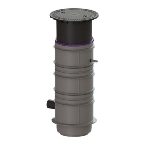
Produktbeschreibung Die Anlage ist zum Einbau ins Erdreich, in den mitgelieferten Schacht mit der lichten Weite 600 mm, außerhalb von Gebäuden vorgesehen. Die Grund- wasserbeständigkeit ist bis max. 2,5 m gegeben. Die Anlage wird für die Bestückung mit einer oder zwei Pumpen (Mono/Duo) hergestellt. Der Aufbau der beiden Pumpen und deren Verrohrung ist symmetrisch. - Page 9 Abb. [2] zeigt Art. Nr. 825811B Abb. [3] zeigt Art. Nr. 825821B Abb. [4] zeigt Art. Nr. 825831B 328-198 Einbau- und Bedienungsanleitung...
-
Page 10: Maße Und Gewichte
Maße und Gewichte KTP 500 Pumpe mit Schwimmerschalter Pumpe für Schaltgerät 2 Pumpen für Schaltgerät Einbautiefe Art. Nr. Gewicht (kg*) Art. Nr. Gewicht (kg*) Art. Nr. Gewicht (kg*) T in mm Klasse A/B, D A/B, D Klasse A/B, D A/B, D Klasse A/B, D A/B, D T1 800 - 1250... -
Page 11: Technische Daten
3. Technische Daten Angabe\Pumpenart KTP 500 GTF 1200 STZ 1000 Gewicht 7 kg 10 kg 10 kg Leistung P1 / P2 500 W / 320 W 1400 W /840 W 1200 W / 690 W Drehzahl 2800 min-1 2650 min-1 2800 min-1 Betriebsspannung 230 V;... - Page 12 Rohranschlüsse [ m ] KTP 500 GTF 1200 /STZ 1000 Zulauf [DN] KTP 500 Anschluss Druckleitung [DN] Kabelleerrohr [DN] Entlüftung [DN] Q [ m 3 /h ] H [ m ] Nutzvolumina Mono Anlage mit KTP 500 GTF 1200/STZ 1000 Schwimmerschalter GTF 1200 Nutzvolumen [l]...
-
Page 13: Montage
4. Montage VORSICHT! Statik für Verkehrssicherheit beachten. Schachtverbau für Lastklasse D kann eine Lastverteilungsplatte, 30cm Beton: 0,18m x 2,3m x 2,3m (Stärke x Höhe x Breite) erforderlich machen. 30cm ▶ Erforderliche Lastklasse und Statik gemäß Umgebung/Nutzungsbedingungen ermitteln. 30cm ▶ Standardstraßenaufbau gemäß Richtlinien für Anlage von Straßen einhalten. Bodenaushub 30cm 1 Eignung von Produkt(-variante) für Umgebungsbedingungen (... -
Page 14: Rohranschluss (➲ Abb. [1] Auf Seite 8)
Rohranschluss ( ➲ Abb. [1] auf Seite 8) ▶ Zulaufleitung anschließen (Gefälle beachten, ggf. Doppelmuffe verwenden). ▶ Kabelleerrohr einführen. ▶ Entlüftungsleitung einführen (Leitung über Dach führen) Teleskopisches Aufsatzstück montieren ▶ Teleskopisches Aufsatzstück probeweise aufsetzen ( ➲ Abb. [7]). ▶ Aufsatzstück entsprechend Bodenniveau anpassen (bei Aufliegen auf Kabel- leerrohr entsprechend kürzen, z. -
Page 15: Pumpe Und Steigleitung Anschließen (➲ Abb. [8])
Pumpe und Steigleitung anschließen ( ➲ Abb. [8]) ▶ Anschlussstutzen mit Dichtung auf Pumpe montieren. ▶ Steigleitung inkl. Schlauchverbindung auf Stutzen aufschieben. ▶ Pumpe inkl. Steigleitung am Haltegriff in den Schacht hineinlassen. ▶ Verriegelungshebel schließen. ▶ ggf. Höhe der Steigleitung anpassen: ▶... -
Page 16: Niveauerfassung Montieren (➲ Abb. [9] )
Niveauerfassung montieren ( Abb. [9] ). ➲ Anlagen deren Pumpensteuerung mittels Schwimmerschalter ausgeführt ist, T2/3 verfügen über keine Schaltgeräte und keine Alarmsonde. In diesem Fall Hand- lungsschritte welche das Wort „Schaltgerät“ oder „Sonde“ enthalten, ignorieren. ▶ Alarmsonde an folgende Position montieren ➊... -
Page 17: Inbetriebnahme
5. Inbetriebnahme Für die Inbetriebnahme von Hebeanlagen ist die EN 12056-4 zu beachten. Prüfung der Anlage Bei Schwarzwasserbetrieb darf die Pumpe nur so eingesetzt werden, dass kein Lufteintritt ins Pumpengehäuse möglich ist. Der Lauf der Pumpen ohne Wasser führt zu erhöhtem Verschleiß und möglicher Funkenbildung. Vor Inbetriebnahme sind folgende Punkte zu prüfen: •... -
Page 18: Wartung
Pumpe und Druckleitung warten: ▶ Verriegelungshebel öffnen. ➊ ▶ Druckleitung komplett mit Pumpe am Griff herausziehen ➋ ▶ Pumpenteile auf Verformung und Ablagerungen prüfen, ggf. KESSEL-Service kontaktieren. ▶ Leichtgängigkeit der beweglichen Teile sicherstellen. ▶ Alarmsonde herausziehen. ➌ Schutzrohr abklipsen ggf. beides in Abb. - Page 19 Rückschlagklappe warten ▶ Rasthebel der Rückschlagklappe betätigen. ➊ ▶ Anschluss mit Rückstauklappe wegziehen. ➋ VORSICHT! angestautes Abwasser läuft aus! ▶ Anschluss mit Rückstauklappe in Wasserbad reinigen. ▶ Beweglichkeit der Rückschlagklappe sicherstellen. ▶ Schachtsystem auf starke Verunreinigungen prüfen, falls erforderlich reinigen. Spitze Geräte sind nicht geeignet. Elektrischer Komponenten überprüfen: ▶...
- Page 20 Einbau- und Bedienungsanleitung 328-198...
-
Page 21: Www.kessel.de/Service/Kundenservice.html
Content Dear customer, As a premium manufacturer of innovative products for draining technology, Notes on this manual KESSEL offers integrated system solutions and customer-oriented service. We Safety hereby aspire to the highest quality standards and focus firmly on sustain- Personnel/qualification... -
Page 22: Notes On This Manual
1. Notes on this manual 2. Safety The following conventional representations make it easier to navigate the The following symbols are used: manual: Icon Meaning Symbol Explanation Isolate device! See Figure 1 Position number 5 in Figure Observe the instructions for use Action step in figure ➊➋➌➍➎➏➐➑➒➓... -
Page 23: Personnel/Qualification
▶ prepare a risk assessment ▶ identify and demarcate corresponding hazard zones ▶ carry out safety training, ▶ secure the system against unauthorised use. Person1 Approved activities on KESSEL systems Visual inspection, inspection, Operating company change of battery Emptying, cleaning Technical expert,... -
Page 24: General Safety Notes
General safety notes The manuals for the system and parts thereof as well as the maintenance The control unit and the float switch or level control are live and must not be records and handover certificates must be kept available near the system. opened. -
Page 25: Intended Use
▶ Do not store or consume any food in the same room. Intended use ▶ Avoid touching the surface, remove visible dirt. The system is to be used as a mono system with one pump in single-family homes and as a duo system in multi-family homes, industrial buildings and ▶... -
Page 26: Product Description
Product description The system has been designed for underground installation in the inspection chamber provided with the clear width 600 mm, outside buildings. Groundwa- ter resistance is given up to max. 2.5 m. The system is produced for equipping with one or two pumps (mono/duo). The layout of the two pumps and their piping is symmetrical. - Page 27 Fig. [2] shows art. # 825811B Fig. [3] shows art. # 825821B Fig. [4] shows art. # 825831B 328-198 Installation and operating manual...
-
Page 28: Dimensions And Weights
Dimensions and weights KTP 500 Pump with float switch Pump for control unit 2 pumps for control unit Installation depth Art. # Weight (kg*) Art. # Weight (kg*) Art. # Weight (kg*) T in mm Class A/B, D A/B, D Class A/B, D A/B, D Class A/B, D... -
Page 29: Technical Data
3. Technical data Specification/pump KTP 500 GTF 1200 STZ 1000 type Weight 7 kg 10 kg 10 kg Power P1 / P2 500 W / 320 W 1400 W /840 W 1200 W / 690 W 2800 rpm 2650 rpm 2800 rpm Speed Operating voltage... - Page 30 Pipe connections [ m ] KTP 500 GTF 1200 /STZ 1000 Inlet [DN] KTP 500 Pressure pipe connection [DN] Cable conduit [DN] Ventilation [DN] Q [ m 3 /h ] Useful volumes H [ m ] Mono system with KTP 500 GTF 1200/STZ 1000 float switch GTF 1200...
-
Page 31: Bahnhofstraße
4. Installation CAUTION! Heed the static calculations for traffic safety Chamber installation for load class D can make a load distribution 30cm plate, concrete: 0.18m x 2.3m x 2.3m (thickness x height x width) necessary. 30cm ▶ Determine the necessary load class and static calculations in accordance with the environment/conditions of use. -
Page 32: Pipe Connection (➲ Ill. [1] On Page 26)
Pipe connection (➲ Fig. [1] on page 26) ▶ Connect supply pipe (heed gradient, use double muff if appropriate). ▶ Insert cable conduit. ▶ Insert ventilation pipe (route pipe via roof) Mount vertically adjustable upper section ▶ Set vertically adjustable upper section in place provisionally (➲ Fig. [7]). ▶... -
Page 33: Connect Pump And Riser Pipe (➲ Illill. [8])
Connect pump and riser pipe (➲ Fig. [8]) ▶ Fit connection socket with sealing gasket to pump. ▶ Push riser pipe incl. hose connection onto socket. ▶ Lower pump incl. riser pipe into the chamber by the handle. ▶... -
Page 34: Install The Level Detection (➲ Ill. [9] )
Install the level detection (➲ Fig. [9] ). L Systems whose pump control is equipped with float switches do not have T2/3 control units and alarm probes. In this case, ignore steps which include the word „control unit“ or „probe“. ▶... -
Page 35: Putting Into Operation
5. Putting into operation EN 12056-4, must be heeded when lifting stations are put into operation. Checking the system L During black water operation, the pump may only be used in such a way that no air can get into the pump housing. Running the pump without water leads to increased wear and possible sparking. -
Page 36: Maintenance
▶ Open the locking lever ➊. ▶ Pull the pressure pipe complete with pump out by the handle ➋. ▶ Check pump components for distortion and deposits, contact KESSEL Service if necessary. ▶ Ensure the moving parts can move easily. - Page 37 Backwater flap maintenance ▶ Actuate the locking lever of the backwater flap ➊ ▶ Pull the connection with backwater flap away ➋, CAUTION! backed up water will escape. ▶ Clean the connection with backwater flap in a water bath. ▶ Make sure that the backwater flap can move freely. ▶...
- Page 38 Installation and operating manual 328-198...
-
Page 39: Instructions De Pose Et D'utilisation
Informations spécifiques aux présentes instructions En qualité de producteur de pointe de produits novateurs dans le domaine Sécurité de la technique d’assainissement, KESSEL propose des réponses systéma- tiques globales et un service orienté aux besoins de la clientèle. Nous misons Personnel / qualification simultanément sur les normes de qualité... -
Page 40: Informations Spécifiques Aux Présentes Instructions
1. Informations spécifiques aux présentes instructions 2. Sécurité Les conventions de représentation suivantes facilitent l’ o rientation : Les instructions emploient les pictogrammes suivants : Pictogramme / Reproduction Explication Signification label voir figure 1 Numéro de repère 5 de la figure Activer l’ a ppareil ! Action de la figure ➊➋➌➍➎➏➐➑➒➓... -
Page 41: Personnel / Qualification
▶ de veiller à la mise en pratique de formations se rapportant aux consignes de sécurité, ▶ de le protéger contre l’utilisation par des personnes non autorisées Person1 Activités autorisées sur les systèmes KESSEL Contrôle visuel, inspection, Exploitant remplacement de la batterie... -
Page 42: Consignes De Sécurité Générales
Consignes de sécurité générales ▶ La directive 0100 de l‘association allemande des ingénieurs électricien (VDE) est applicable à tous les travaux électriques effectués sur le système. Les instructions spécifiques au système et aux composants du système ainsi ▶ Le système doit être alimenté par un dispositif différentiel à courant que les procès-verbaux de maintenance et de réception doivent toujours se résiduel (RCD) avec courant assigné... - Page 43 Risque dû au poids élevé du système pendant le transport ! Les pompes peuvent démarrer brusquement. ▶ Vérifier le poids du système / des composants du systèm au chap. „3. Désactiver toujours le système avant la maintenance ou les réparations ou couper l’alimentation secteur. Caractéristiques techniques“.
-
Page 44: Utilisation Conforme À L'usage Prévu
Utilisation conforme à l‘usage prévu Le système est conçu comme système Mono avec une pompe pour un emploi dans des maisons individuelles et comme système Duo pour un emploi dans des immeubles collectifs, des édifices commerciaux et industriels et des établissements publics. -
Page 45: Description Du Produit
Description du produit Le système est prévu pour la pose à enterrer dans le regard fourni d’une large- ur hors tout de 600 mm, à l’ e xtérieur du bâtiment. Le système est étanche aux eaux souterraines jusqu’à une profondeur maximale de 2,5 m. Le système est fabriqué... - Page 46 fig. [3] montre la Réf. n° 825821B fig. [2] montre la Réf. n° 825811B fig. [4] montre la Réf. n° 825831B Instructions de pose et d’utilisation 328-198...
-
Page 47: Dimensions Et Poids
Dimensions et poids KTP 500 Pompe avec interrupteur à flotteur Pompe avec gestionnaire 2 pompes avec gestionnaire Réf. n° Poids (kg*) Réf. n° Poids (kg*) Réf. n° Poids (kg*) Profondeur ‘installation P en mm Classe A/B, D A/B, D Classe A/B, D A/B, D Classe A/B, D A/B, D... -
Page 48: Caractéristiques Techniques
3. Caractéristiques techniques Indication\type de KTP 500 GTF 1200 STZ 1000 pompe Poids 7 kg 10 kg 10 kg Puissance P1 / P2 500 W / 320 W 1400 W / 840 W 1200 W / 690 W 2800 min-1 2650 min-1 2800 min-1 Régime Tension de service... - Page 49 Raccords de tuyaux [ m ] KTP 500 GTF 1200 / STZ 1000 Entrée [DN] KTP 500 Raccord de la conduite de refoulement [DN] Conduit de câbles [DN] Purge d’ a ir [DN] Q [ m 3 /h ] Volume utile H [ m ] Système Mono avec GTF 1200 / STZ...
-
Page 50: Montage
4. Montage ATTENTION! Observer la statique conforme à la sécurité routière. La pose d’un regard conforme à la classe de charge D peut exiger une 30cm plaque de répartition de la charge, béton : 0,18 m x 2,3 m x 2,3 m (épaisseur x hauteur x largeur). 30cm ▶... -
Page 51: Raccord De Tuyaux (➲ Fig. [1] À La Page 45)
Raccord de tuyaux ( ➲ fig. [1] à la page 45) ▶ Raccorder la conduite d‘entrée (observer la dénivellation, si nécessaire utiliser un manchon double). ▶ Introduire le conduit pour câbles. ▶ Introduire la conduite de purge d‘air (amener la conduite jusqu’au-dessus du toit) Montage de la rehausse télescopique ▶... -
Page 52: Raccordement De La Pompe Et De La Conduite Ascendante (➲„Fig. [8]")
Raccordement de la pompe et de la conduite ascendante ( ➲ „fig. [8]“) ▶ Monter la tubulure de raccordement avec le joint d‘étanchéité sur la pompe ➊ ▶ Glisser la conduite ascendante y compris le raccord de tuyaux sur la tubulure ▶... -
Page 53: Montage De La Détection Du Niveau ( Fig. [9] )
Montage de la détection du niveau ( ➲ fig. [9] ). Les systèmes avec une pompe commandée par un interrupteur à flotteur T2/3 n’ o nt pas de gestionnaire et de sonde d‘alarme. Ignorer les étapes cont- enant le mot « Gestionnaire » ou « Sonde » dans un tel cas. ▶... -
Page 54: Mise En Service
5. Mise en service Respecter la norme EN 12056-4 lors de la mise en service des postes de relevage. Test du système Veillez à exclure toute entrée d‘air dans le carter de la pompe en exploitation avec des eaux vannes. Le fonctionnement des pompes sans eau augmente l‘usure et crée un risque de formation d‘étincelles. -
Page 55: Maintenance
▶ Extraire la conduite de refoulement complètement avec la pompe au niveau de la poignée ➋ fig. [10] ▶ Vérifier l’absence de déformations et d’incrustations des pièces des pom- pes, si nécessaire contacter le SAV de KESSEL. 328-198 Instructions de pose et d’utilisation... - Page 56 ▶ Vérifier la souplesse de fonctionnement des pièces ou éléments mobiles. ▶ Extraire la sonde d‘alarme ➌ , déclipser la gaine de protection, si nécessai- re nettoyer les deux pièces dans un bain-marie. ▶ Extraire la cloche submersible et la nettoyer à l‘eau ➍...
-
Page 57: Istruzioni Per L'installazione E L'uso
Cara cliente, caro cliente, Indicazioni sulle presenti istruzioni in qualità di produttore premium di prodotti innovativi per la tecnica di drenaggio, KESSEL offre soluzioni di sistema integrate e un servizio orientato al Sicurezza cliente. Puntiamo sui massimi standard qualitativi e ci impegniamo coerente- Personale/Qualifica mente per la sostenibilità... -
Page 58: Indicazioni Sulle Presenti Istruzioni
1. Indicazioni sulle presenti istruzioni 2. Sicurezza Le seguenti convenzioni illustrative semplificano l’ o rientamento: Sono impiegati i simboli seguenti: Simbolo Spiegazione Simbolo Significato vedere figura 1 Mettere fuori tensione l’ a pparecchio! [1-5] Posizione numero 5 della figura 1 Passaggio procedurale nella figura ➊➋➌➍➎➏➐➑➒➓... -
Page 59: Personale/Qualifica
▶ determinare e segnalare delle zone di rischio adeguate, ▶ effettuare la formazione per la sicurezza, ▶ impedire l’uso da parte di persone non autorizzate Persona 1 Mansioni ammesse sugli impianti KESSEL Controllo visivo, ispezione, Esercente sostituzione della batteria Svuotamento, pulizia... -
Page 60: Avvertenze Di Sicurezza Generali
Avvertenze di sicurezza generali una corrente di guasto nominale non superiore a 30 mA. Le istruzioni dell’impianto e i componenti dell’impianto, al pari del verbale di consegna e manutenzione, devono essere mantenuti disponibili presso Il quadro elettrico e i galleggianti, nonché il comando del livello, sono sotto l’impianto. -
Page 61: Uso Conforme Alla Destinazione
Superficie contaminata! Uso conforme alla destinazione L’impianto e l’ambiente circostante possono essere contaminati dai L’impianto deve essere impiegato quale impianto Mono con una pompa per batteri. l’impiego nelle case unifamiliari e quale impianto Duo per l’impiego nelle case plurifamiliari, negli edifici commerciali e nelle strutture pubbliche. Il fluido ▶... -
Page 62: Descrizione Del Prodotto
Descrizione del prodotto L’impianto è destinato all’installazione nel terreno, nel pozzetto in dotazione con diametro di luce di 600 mm, al di fuori degli edifici. La resistenza all’acqua freatica è garantita fino a 2,5 m al massimo. L’impianto è prodotto per la dotazione con una o due pompe (Mono/Duo). - Page 63 Fig. [2] mostra il codice articolo 825811B Fig. [3] mostra il codice articolo 825821B Fig. [4] mostra il codice articolo 825831B 328-198 Istruzioni per l’installazione e l’uso...
-
Page 64: Misure E Pesi
Misure e pesi KTP 500 Pompa con interruttore a galleggiante Pompa per quadro elettrico 2 pompe per quadro elettrico Profondità di posa Codice articolo Peso (kg*) Codice articolo Peso (kg*) Codice articolo Peso (kg*) T in mm Classe A/B, D A/B, D Classe A/B, D A/B, D... -
Page 65: Dati Tecnici
3. Dati tecnici Indicazione/tipo di KTP 500 GTF 1200 STZ 1000 pompa Peso 7 kg 10 kg 10 kg Potenza P1 / P2 500 W / 320 W 1400 W / 840 W 1200 W / 690 W 2800 min-1 2650 min-1 2800 min-1 Numero di giri... - Page 66 Collegamenti dei tubi [ m ] GTF 1200 / KTP 500 STZ 1000 KTP 500 Entrata [DN] Collegamento al condotto di mandata [DN] Tubo vuoto per cavi [DN] Q [ m 3 /h ] Sfiato [DN] H [ m ] Volumi utili Impianto Mono con GTF 1200/STZ...
-
Page 67: Montaggio
4. Montaggio ATTENZIONE! Tenere in considerazione la statica per la sicurezza della circolazione. 30cm L’installazione di un pozzetto per la classe di carico D può rendere necessaria una piastra di distribuzione del carico di calcestruzzo: 0,18 30cm m x 2,3 m x 2,3 m (spessore x altezza x larghezza). ▶... -
Page 68: Collegamento Dei Tubi (➲ Ill. [1] A Pagina 62)
Collegamento dei tubi ( ➲ Fig. [1] a pagina 62) ▶ Collegare il condotto di alimentazione (tenere conto della pendenza, eventual- mente usare un manicotto doppio). ▶ Inserire il tubo vuoto per cavi. ▶ Inserire il condotto di sfiato (portare il condotto sopra il tetto). Montaggio della prolunga telescopica ▶... -
Page 69: Collegamento Del. Pompa E Del. Colonna Montante (➲ Ill. [8])
Collegamento della pompa e della colonna montante ➲ Fig. [8]) ▶ Montare il bocchettone di collegamento con guarnizione sulla pompa ➊ ▶ Spingere la colonna montante sul bocchettone, compreso il collegamento per tubo flessibile ▶ Lasciare entrare la pompa comprensiva della colonna montante nel pozzetto tenendola dalla maniglia ... -
Page 70: Montaggio Della Rilevazione Del Livello (➲ Ill. [9] )
Montaggio della rilevazione del livello ( ➲ Fig. [9] ). Gli impianti il cui comando della pompa avviene tramite l’interruttore a T2/3 galleggiante non dispongono di nessun quadro elettrico e di nessuna sonda di allarme. In questo caso, ignorare i passaggi contenenti la parola “quadro elettrico”... -
Page 71: Messa In Funzione
5. Messa in funzione Per la messa in funzione delle stazioni di sollevamento, rispettare la norma EN 12056-4. Controllo dell’impianto In caso di funzionamento con le acque nere, la pompa può essere impiegata solo in modo che nel corpo della pompa non sia possibile alcuna infiltrazione d’aria. -
Page 72: Manutenzione
▶ Estrarre il condotto di mandata completo di pompa dalla maniglia ➋ ▶ Controllare la presenza di deformazioni e depositi sulle parti della pompa, eventualmente contattare il servizio KESSEL. ▶ Accertare la mobilità della parti mobili. ▶ Estrarre la sonda di allarme ➌... - Page 73 Manutenzione del clapet di non ritorno ▶ Azionare la leva di arresto del clapet di non ritorno ➊ ▶ Tirare via il collegamento con il clapet antiriflusso ➋ PRUDENZA! Fuori- uscita delle acque di scarico accumulatesi! ▶ Lavare il collegamento con il clapet antiriflusso in un bagno d’acqua. ▶...
- Page 74 Istruzioni per l’installazione e l’uso 328-198...
-
Page 75: Inbouw En Bedieningshandleiding
Inhoud Beste klant, Als premium fabrikant van innovatieve producten voor de afwateringstechniek Informatie over deze handleiding biedt KESSEL op de totaliteit gerichte systeemoplossingen en op de klant Veiligheid georiënteerde service. Wij stellen hierbij maximale kwaliteitsnormen en Personeel/kwalificatie zetten consequent in op duurzaamheid - niet alleen bij de productie van onze... -
Page 76: Informatie Over Deze Handleiding
1. Informatie over deze handleiding 2. Veiligheid De volgende weergaveconventies maken de oriëntatie eenvoudiger: De volgende symbolen worden gebruikt: Afbeelding Toelichting Teken Betekenis zie afbeelding 1 Apparaat vrijschakelen! Positienummer 5 van afbeelding Uit te voeren stap op afbeelding ➊➋➌➍➎➏➐➑➒➓ Gebruiksaanwijzing in acht nemen 1 Controleren of de handmatige Voorwaarde voor handeling besturing werd geactiveerd. -
Page 77: Personeel/Kwalificatie
▶ het maken van een gevarenbeoordeling, ▶ het vaststellen en aantonen van navenante gevarenzones, ▶ het uitvoeren van de veiligheidsinstructies, ▶ het beveiligen tegen gebruik door onbevoegden Person1 Vrijgegeven activiteiten bij KESSEL installaties Visuele controle, inspectie, Exploitant accuvervanging Leging, reiniging... -
Page 78: Algemene Veiligheidsinstructies
Algemene veiligheidsinstructies De besturingskast alsmede de vlotters resp. niveauregeling staan onder spanning en mogen niet worden geopend. De handleidingen van de installatie en installatieonderdelen alsmede de onderhouds- en overdrachtsprotocollen moeten bij de installatie beschikbaar Er moet worden gewaarborgd dat de elektriciteitskabels en alle elektrische worden gehouden. -
Page 79: Reglementair Gebruik
▶ Geen voedingsmiddelen in dezelfde ruimte bewaren of consumeren. Reglementair gebruik ▶ Het oppervlak niet aanraken, zichtbaar vuil verwijderen. De installatie kan als mono-installatie met een pomp voor gebruik in eenge- zinswoningen en als duo-installatie voor gebruik in meergezinswoningen, ▶ Na beëindiging van de werkzaamheden eerst de handen wassen. zakelijke en overheidsgebouwen worden gebruikt. -
Page 80: Productomschrijving
Productomschrijving De installatie is bedoeld voor plaatsing in de grond met de meegeleverde schacht met een binnenwerkse breedte van 600 mm buiten het gebouw. De maximale grondwaterbestendigheid bedraagt 2,5 m. De installatie werd voorbereid voor het gebruik met één of twee pompen (mono/duo). De opbouw van de beide pompen en de bijbehorende buizen is symmetrisch. - Page 81 Afb. [2] toont art. nr. 825811B Afb. [3] toont art. nr. 825821B Afb. [4] toont art. nr. 825831B 328-198 Inbouw- en bedieningshandleiding...
-
Page 82: Maten En Gewichten
Maten en gewichten KTP 500 Pomp met vlotterschakelaar Pomp voor besturingskast 2 pompen voor besturingskast Inbouwdiepte Art. nr. Gewicht (kg*) Art. nr. Gewicht (kg*) Art. nr. Gewicht (kg*) D in mm Klasse A/B, D A/B, D Klasse A/B, D A/B, D Klasse A/B, D A/B, D D1 800 - 1.250... -
Page 83: Technische Gegevens
3. Technische gegevens Taak/pomptype KTP 500 GTF 1200 STZ 1000 Gewicht 7 kg 10 kg 10 kg Vermogen P1 / P2 500 W/320 W 1.400 W/840 W 1.200 W/690 W Toerental 2.800 omw/min 2.650 omw/min 2.800 omw/min Bedrijfsspanning 230 V; 50 Hz 230 V;... - Page 84 Buisaansluitingen [ m ] GTF 1200 /STZ KTP 500 1000 KTP 500 Aanvoer [DN] Aansluiting persleiding [DN] Lege kabelbuis [DN] Q [ m 3 /h ] Ontluchting [DN] H [ m ] Netto inhoud Mono-installatie met GTF 1200/STZ KTP 500 GTF 1200 vlotterschakelaar 1000...
-
Page 85: Montage
4. Montage LET OP! Statistiek voor de verkeersveiligheid in acht nemen. Voor de montage van de schacht in belastingsklasse D kan een 30cm lastverdelingsplaat, beton: (dikte x hoogte x breedte) 0,18 m x 2,3 m x 2,3 m nodig zijn. 30cm ▶... -
Page 86: Buisaansluiting (➲ Afb. [1] Op Pagina 80)
Buisaansluiting ( ➲ Afb. [1] op pagina 80) ▶ Toevoerleiding aansluiten (rekening met verval houden, evt. dubbele mof gebruiken). ▶ Lege kabelbuis invoeren. ▶ Ontluchtingsleiding invoeren (leiding over het dak geleiden) Telescopisch opzetstuk monteren ▶ Telescopisch opzetstuk als proef opzetten ( ➲... -
Page 87: Pomp En Stijgbuis Aansluiten (➲ Afb. [8])
Pomp en stijgbuis aansluiten ( ➲ Afb. [8]) ▶ Aansluitmof met pakking op de pomp monteren ➊ ▶ Stijgbuis incl. slangverbinding op de mof schuiven ▶ Pomp incl. stijgbuis aan de handgreep in de schacht laten zakken ▶ Vergrendelingshendel sluiten. ▶... -
Page 88: Niveaudetectie Monteren (➲ Afb. [9] )
Niveaudetectie monteren ( ➲ Afb. [9] ). Installaties waarbij de pompregeling door middel van vlotterschakelaar T2/3 plaatsvindt, beschikken niet over een besturingskast en alarmsonde. In dat geval de stappen die het woord „besturingskast“ of „sonde“ bevatten, gewoon overslaan. ▶ Alarmsonde op de onderstaande positie monteren ➊... -
Page 89: Inbedrijfstelling
5. Inbedrijfstelling Voor het inbedrijfstellen van opvoerinstallaties moet EN 12056-4 in acht worden genomen. Installatie controleren Bij gebruik voor zwart water mag de pomp alleen zo worden gebruikt, dat er geen lucht in de pompbehuizing kan binnendringen. Als de pompen zonder water draaien, leidt dat tot extra slijtage en mogelijk tot vonkvorming. -
Page 90: Onderhoud
➊ ▶ Persleiding compleet met pomp aan de handgreep eruit trekken ➋ ▶ Pomponderdelen op vervorming en afzettingen controleren, evt. contact opnemen met de KESSEL-Service. ▶ Ervoor zorgen dat alle bewegende delen soepel lopen. ▶ Alarmsonde eruit trekken ➌ , klem van beschermbuis losmaken en evt. - Page 91 Terugslagklep onderhouden ▶ Op vergrendeling van de terugslagklep drukken ➊ ▶ Aansluiting met terugslagklep verbreken ➋ VOORZICHTIG! Er stroomt opgehoopt afvalwater uit! ▶ Aansluiting met terugslagklep in een waterbad reinigen. ▶ Ervoor zorgen dat de terugslagklep soepel kan bewegen. ▶ Schachtsysteem controleren of sterke verontreinigingen, indien nodig reinigen.
- Page 92 Inbouw- en bedieningshandleiding 328-198...
-
Page 93: Instrukcja Zabudowy I Obsługi
Zawartość Szanowna Klientko, szanowny Kliencie! Wskazówki dotyczące tej instrukcji Jako producent najwyższej klasy innowacyjnych produktów z zakresu techniki odwadniania firma KESSEL oferuje kompleksowe rozwiązania systemowe i Bezpieczeństwo serwis odpowiadający potrzebom klientów. Stawiamy przy tym na najwyższe Personel/kwalifikacje standardy jakości i konsekwentnie dążymy do zrównoważonego rozwoju, nie Ogólne wskazówki bezpieczeństwa... -
Page 94: Wskazówki Dotyczące Tej Instrukcji
1. Wskazówki dotyczące tej instrukcji 2. Bezpieczeństwo Poniższe formy przedstawienia ułatwiają orientację: Używane są następujące symbole: Przedstawienie Objaśnienie Znak Znaczenie patrz rys. 1 Odłączyć urządzenie od prądu! numer pozycji 5 na rys. Krok postępowania na rysunku ➊➋➌➍➎➏➐➑➒➓ Przestrzegać instrukcji obsługi 1 Sprawdzić, czy aktywowane Warunek postępowania zostało sterowanie ręczne. -
Page 95: Personel/Kwalifikacje
▶ sporządzenia oceny zagrożenia, ▶ wyznaczenia i oznakowania odpowiednich stref zagrożenia, ▶ przeprowadzenia instruktaży postępowania w razie niebezpieczeństwa, ▶ zabezpieczenia przed użyciem przez osoby nieupoważnione Osoba1 Dozwolone czynności przy urządzeniach KESSEL Oględziny, inspekcja, wymiana Użytkownik baterii Opróżnianie, czyszczenie Osoba o odpowiednich kwalifikacjach, (wewnątrz), kontrola... -
Page 96: Ogólne Wskazówki Bezpieczeństwa
Ogólne wskazówki bezpieczeństwa Instrukcje do tego urządzenia i części urządzenia jak również protokoły konser- Urządzenie sterujące i pływaki lub sterowanie poziomem znajdują się pod wacji i przekazania należy przechowywać w pobliżu urządzenia. napięciem i nie wolno ich otwierać. Zapewnić, aby kable elektryczne oraz wszystkie inne elektryczne elementy urządzenia znajdowały się... -
Page 97: Zastosowanie Zgodnie Z Przeznaczeniem
Skażona powierzchnia! Zastosowanie zgodnie z przeznaczeniem Urządzenie i otoczenie mogą być skażone drobnoustrojami. Urządzenie typu Mono z jedną pompą jest przeznaczone do użytku w domach jednorodzinnych, a w wersji Duo do użytku w domach wielorodzinnych, obiek- ▶ Nie przechowywać i nie spożywać żywności w tym samym tach przemysłowych i instytucjach publicznych. -
Page 98: Opis Produktu
Opis produktu Urządzenie jest przeznaczone do zabudowy w ziemi, w dostarczonej studzience o średnicy w świetle 600 mm, poza budynkami. Odporność na wodę gruntową gwa- rantowana jest do głębokości maks. 2,5 m. Urządzenie zostało wyprodukowane z przeznaczeniem na jedną lub dwie pompy (Mono/Duo). Konstrukcja obydwu pomp i ich orurowanie są... - Page 99 Rys. [2] przedstawia art. art. 825811B Rys. [3] przedstawia art. art. 825821B Rys. [4] przedstawia art. art. 825831B 328-198 Instrukcja zabudowy i obsługi...
-
Page 100: Masa I Ciężary
Masa i ciężary KTP 500 Pompa z przełącznikiem pływakowym Pompa do urządzenia sterującego 2 pompy do urządzenia sterującego Głębokość zabud. Nr art. Ciężar (kg*) Nr art. Ciężar (kg*) Nr art. Ciężar (kg*) T w mm Klasa A/B, D A/B, D Klasa A/B, D A/B, D Klasa A/B, D... -
Page 101: Dane Techniczne
3. Dane techniczne Dane / rodzaj pompy KTP 500 GTF 1200 STZ 1000 Ciężar 7 kg 10 kg 10 kg Moc P1 / P2 500 W / 320 W 1400 W / 840 W 1200 W / 690 W Prędkość obrotowa 2800 obr./min 2650 obr./min 2800 obr./min... - Page 102 Przyłącza rur [ m ] GTF 1200 /STZ KTP 500 1000 KTP 500 Dopływ [DN] Przyłącze przewodu tłocznego [DN] Rura elektroinstalacyjna [DN] Q [ m 3 /h ] Odpowietrzanie [DN] H [ m ] Pojemności użytkowe Urządzenie Mono z GTF 1200/STZ GTF 1200 KTP 500 przełącznikiem pływakowym...
-
Page 103: Montaż
4. Montaż OSTROŻNIE! Przestrzegać statyki budowlanej dla 30cm bezpieczeństwa drogowego. Zabudowa w studzience dla klasy obciążenia D może wymagać użycia betonowej płyty zapewniającej rozkład obciążeń o 30cm wymiarach: 0,18 m x 2,3 m x 2,3 m (grubość x wysokość x szerokość). ▶... -
Page 104: Przyłącze Rurowe (➲ Rys. [1] Na Stronie 98)
Przyłącze rurowe ( ➲ Rys. [1] na stronie 98) ▶ Podłączyć przewód dopływowy (przestrzegać spadku, ewentualnie użyć dwukielicha). ▶ Włożyć rurę elektroinstalacyjną. ▶ Włożyć przewód odpowietrzający (poprowadzić przewód powyżej poziomu dachu). Montaż nasady teleskopowej ▶ Nałożyć na próbę nasadę teleskopową ( ➲... -
Page 105: Podłączenie Pompy I Pionu Instalacyjnego (➲ Rys. [8])
Podłączenie pompy i pionu instalacyjnego ( ➲ Rys. [8]) ▶ Zamontować na pompie króciec przyłączeniowy z uszczelką ➊ ▶ Nasunąć na króciec przyłączeniowy pion instalacyjny z przewodem giętkim ▶ Spuścić pompę razem z pionem instalacyjnym do studzienki trzymając za uchwyt ... -
Page 106: Montaż Urządzenia Do Pomiaru Poziomu ( Rys. [9] )
Montaż urządzenia do pomiaru poziomu ( Rys. [9] ) ➲ Urządzenia, których sterowanie pomp wykonane jest w formie przełącznika T2/3 pływakowego, nie posiadają urządzeń sterujących ani sondy alarmowej. W takim przypadku należy zignorować kroki postępowania zawierające słowa „urządzenie sterujące“ lub „sonda“. ▶... -
Page 107: Uruchomienie
5. Uruchomienie Podczas uruchamiania przepompowni należy przestrzegać normy EN 12056-4. Kontrola urządzenia Jeżeli urządzenie używane jest do pompowania ścieków zawierających fe- kalia, pompy wolno używać tylko w sposób uniemożliwiający przedostanie się powietrza do wnętrza obudowy pompy. Bieg pomp bez wody prowadzi do zwiększonego zużycia i możliwego powstawania iskier. -
Page 108: Konserwacja
➊ ▶ Wyciągnąć przewód tłoczny razem z pompą trzymając za uchwyt ➋ ▶ Sprawdzić części pompy pod kątem odkształceń i osadów, ewentualnie skon- taktować się z serwisem firmy KESSEL. ▶ Zapewnić lekkobieżność ruchomych części. Rys. [10] ▶ Wyjąć sondę alarmową... - Page 109 Konserwacja klapy zwrotnej: ▶ Otworzyć dźwignię zatrzaskową klapy zwrotnej ➊ ▶ Odsunąć przyłącze z klapą zwrotną ➋ OSTROŻNIE! Wylewają się spiętrzone ścieki! ▶ Wyczyścić przyłącze z klapą zwrotną w kąpieli wodnej. ▶ Zapewnić ruchliwość klapy zwrotnej. ▶ Sprawdzić system studzienki pod kątem dużych zanieczyszczeń, w razie potrze- by wyczyścić.
- Page 110 Instrukcja zabudowy i obsługi 328-198...
- Page 111 328-198 Instrukcja zabudowy i obsługi...
- Page 112 Registrieren Sie ihr Produkt online um von einer schnelleren Hilfe zu profitieren! http://www.kessel.de/service/produktregistrierung.html KESSEL AG, Bahnhofstr. 31, 85101 Lenting, Deutschland...
Need help?
Do you have a question about the Aqualift S LW600 and is the answer not in the manual?
Questions and answers