Table of Contents
Advertisement
Quick Links
INSTALLATION, OPERATING AND MAINTENANCE INSTRUCTIONS
KESSEL-lifting station Aqualift F (400V) Standard
for wastewater with and without faeces for
free-standing installation in rooms protected from frost
Aqualift F
Installation
The installation and service of this unit should be carried out by
a licensed professional servicer
Name/Unterschrift
Edition 07/2010
Aqualift F Duo
Commissioning
Datum
Instruction
Ort
Product advantages
Simple connection through
moulded connecting pieces
Drilling surfaces for further
connections
Fully automatic operation
Maintenance-friendly
PE-tank
General technical approval
no. Z-53.2-424
LGA
Landesgewerbeamt Bayern
Bauart
Bauart
Bauart
geprüft
geprüft
geprüft
und überwacht
und überwacht
und überwacht
Stempel Fachbetrieb
ID-Nr. 206-818EN
Advertisement
Table of Contents

Related Manuals for Kessel Aqualift F Standard


Summary of Contents for Kessel Aqualift F Standard
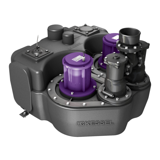
- Page 1 INSTALLATION, OPERATING AND MAINTENANCE INSTRUCTIONS KESSEL-lifting station Aqualift F (400V) Standard for wastewater with and without faeces for free-standing installation in rooms protected from frost Aqualift F Duo Aqualift F Product advantages Simple connection through moulded connecting pieces Drilling surfaces for further...
- Page 2 1. Safety information General safety precautions During installation, operation, maintenance or repairs to the system, please observe the accident pre- vention regulations, the applicable DIN and VDE standards and guidelines, and also the regulations of the local energy and supply companies. The systems may not be operated in explosive areas Electrical hazards This system contains electrical voltages and controls rotating mechanical parts.
- Page 3 When the pump is operated, a noise level is created that may be a nuisance depending on how the pump is installed. If there are maximum noise level stipulations that need to be observed, appropriate mea- sures need to be taken. The sound damping set from KESSEL may also be helpful here. Risk of explosion The inside of the tank is considered to be explosive within the meaning of EN 12050 because the bio- logical digestive process may create flammable gases (hydrogen sulphide, methane gas).
-
Page 4: Table Of Contents
Table of contents ......................Page 1. Safety information Area of application...............Page 2. General System description ..............Page Dimensions................Page 3. Technical data Pumps .................Page Electric switch unit ...............Page Fitting the collecting tank .............Page 4. Installation and assembly Connecting the pipes............Page Setting the pressure level switches ........Page 11 General notes ..............Page 12 5. -
Page 5: General
2. General 2.1 Area of application The lifting stations pump wastewater with and without se- The KESSEL lifting station Aqualift ® F has been designed wage that occurs below the sewer and backwater level fully for free-standing set-up in frost-protected rooms. The res-... -
Page 6: Dimensions
3. Technical data 3.1 Dimensions 3.1.1 Single system 1.1 kW with pressure outlet DN 100, order no. 28645 / 28644 (with non-return valve) Single system 2.2 kW with pressure outlet DN 100, order no. 28647 / 28649 (with non-return valve) DN100 Ø110 DN70... -
Page 7: Pumps
3. Technical data 3.2 Pumps (Aqualift F Mono, Duo) Type 400 V - 1,1 kW 400 V - 2,2 kW Nominal capacity (P2) 1,15 kW 2,4 kW Rated capacity (P1) 1,6 kW 3,1 kW Operating voltage 400 V DS Rated frequency 50 Hz Nominal current 3,2 A... -
Page 8: Electric Switch Unit
3. Technical data 3.3 Electric switch unit 3.3.4 Outputs 3.3.1 General technical data "Malfunction" relay Changeover contact; opening contact, centre contact, Ambient conditions closing contact each max. 2A Permissible temperature range: 0 to 50 °C Permissible air humidity: 10 to 80 % "Warning"... -
Page 9: Fitting The Collecting Tank
The system must be set up at the appropriate spot in the room, aligned horizontally and placed on practical sound-in- sulating material (available as an accessory from KESSEL). The brackets, screws and dowels must be used to fix the lif- ting station to the floor to prevent movement or twisting. - Page 10 (for inlet pipe or manual diaphragm pump) using bore hole with saw cap*, fitting of a suitable greases seal* and insertion of a suitable plastic pipe (see Fig. E) Tank-lifting station Pipe duct seal Abb. C: Pipe connection Tank-lifting station Abb. E * KESSEL accessory part...
-
Page 11: Setting The Pressure Level Switches
Inlet pipe Before commencing any work on the switchgear, the The inlet pipe must be laid at a gradient to the KESSEL lif- pump or the level control, the master switch and cut-outs ting station in accordance with DIN 1986 and be routed as must be switched off and secured against being re- straight as possible. -
Page 12: General Notes
Special lengths of this cable can be ordered di- Screw connections not used must always be sealed properly. rectly from KESSEL. – The cable must be routed at a constant gradient from the switch unit to the lifting station. - Page 13 5. Electrical connections The individual connection jobs are listed in the following table and in the connection diagrams on pages 27 and 29. The ex- planations in chapter 8, Electric switch unit, must also be heeded (position of the control elements, view of the inside of the switch unit).
- Page 14 5. Electrical connections SINGLE SYSTEM- Heed safety instructions! Work to be done Switch unit Switch unit from model year 01/10 up to model year 12/09 • The terminal block of the level inputs must not be connected with any other circuit. •...
- Page 15 5. Electrical connections TWIN SYSTEM- HEED SAFETY INSTRUCTIONS! Work to be done Switch unit Switch unit from model year 01/10 up to model year 12/09 Battery connection • Both batteries (2 x 9V block) must • Der Akku (1 x 9V-Block) ist in die Akku- (rechargeable batteries up to 12/09) be connected on the board.
-
Page 16: Checks
5. Electrical connections TWIN SYSTEM- HEED SAFETY INSTRUCTIONS! Work to be done Switch unit Switch unit from model year 01/10 up to model year 12/09 • The terminals are marked with switch symbols. • The "malfunction" and "alarm" messages are is- •... -
Page 17: Configuration Of Switch Unit
5. Electrical connections 5.6 Configuration of switch unit (up to model year 12/09) Configuration of the control is carried out in the factory using switches S601 ... S604 between the terminal blocks of the level inputs and thermal protection input. For safety reasons, these must be checked according to the following descriptions. Pre-settings or reference settings are highlighted grey. -
Page 18: General Notes
6. Initial operation 6.1 General instructions Check the system installation/cabling carefully before you put the system into operation. Is the protective earthed con- Initial operation ductor working? Have the relevant standards/guidelines Initial operation must be carried out by a qualified expert, with been heeded, particularly with a view to the potentially ex- the direct supplier of the wastewater lifting station responsi- plosive area? -
Page 19: Functional Description
6. Initial operation 6.4.1 Operating the switch unit up to model year 12/09) When the maximum running time limit has been exceeded, the malfunction message and switch-off of the respective 6.4.1 "Automatic" operating model pump take place as with the single system. The respective pump can only return to operation when the "alarm reset"... -
Page 20: Notes On The Pump
7. Inspection and maintenance The system must be checked once every month by the ope- 7.2 Notes on the aerating device rator through observation of the switching routine for opera- tional ability and leaks. The aerating device can be used to completely empty the pressure pipe through manual lifting of the backwater flap on CAUTION: the lifting system. -
Page 21: Notes On The Electrical Switch Unit
7. Inspection and maintenance Fig. 4 Fig. 5 7.3 Notes on the electric switch unit • The battery / rechargeable battery is a wearing part and with the environment in mind. They may only be replaced should be checked and changed if necessary once a year by batteries of the same type. -
Page 22: General Malfunctions
• Remove the object from the pressure fitting or pressure pipe • Pumps are worn, have them replaced • Wrong lifting station design, clarification through KESSEL Customer Services Put aeration device into operating position Aeration device not in operating position Check direction of rotation, if incorrect swap... - Page 23 (particularly motor protection switch) System switched on and off too often on ac- count of high inlet quantities, clarification with KESSEL customer services Contactors too hot on account of Check system for switching malfunctions. switching malfunctions...
-
Page 24: Malfunction Messages
8. Malfunctions and troubleshooting Malfunction messages / remedial measures (from model year 01/10) = off l == flashing slowly ❍ = flashing quickly = lit Battery fault - Acknowledge alarm and alarm key - Check if batteries are connected - Replace discharged batteries - After acknowledging the signal tone, press the alarm key again -->... - Page 25 8. Malfunctions and troubleshooting Sensor fault - Drop in pressure: Water level has fallen by 12 mm without the pump having been running --> Pump the submersible pipe/plunger free by hand --> Check the air hose for leaks Duo Pump 1/2 Rotary field / phase fault - Rotary field fault: Wrong rotary field for mains connection of switch unit -->...
-
Page 26: Irregular Level States
8. Malfunctions and troubleshooting Relay fault Power contactor no longer switches off --> Disconnect switch unit from the mains --> Replace contactor --> Contact Customer Services Duo Pump 1 Duo Pump 2 Level fault Level fault (only with pressure diaphragm switch): Control cable to the switch unit is not laid on a continual gradient -->... -
Page 27: Internal Monitoring
8. Malfunctions and troubleshooting 8.2.2 Internal monitoring The control unit evaluates the signals of the phase/rotary field or on twin systems with monitoring, motor protection switch and motor temperature – Phase/rotary field sensor regardless of the configuration. In the event of a mal- –... -
Page 28: Switch Unit (From Model Year 01/10)
9. Control unit 9.1 Switch unit (from model year 01/10) R 3 -0,2mm Aqualift F Mono 400V Kurzbedienungsanleitung: Œ Netzverbindung herstellen grüne Netzanzeige Automatikbetrieb Niveau-Anzeige leuchtet Pumpniveau erreicht Pumpen-Anzeige leuchtet Display/indicator panel Pumpe läuft NIVEAU LEVEL Ž Unterdrücken des akustischen Pilot lamp indicating readiness for operation Alarms mit... -
Page 29: Switch Unit (Up To Model Year 12/09)
9. Control unit 9.1.2 Circuit diagram twin system from model year 01/10) 9.2 Switch unit (up to model year 12/09) 9.2.1 Switch unit for single system (up to model year 12/09) Description of the display and control elements Display elements (LED’s) Operation yellow Voltage supply OK Normal mode... - Page 30 9. Control unit • The operating elements can be accessed once the trans- ched voltage-free first. In case of doubt, a qualified elec- parent housing cover has been removed. The housing trician must always be consulted. cover may be removed for operational purposes, but it only •...
- Page 31 9. Control unit 9.2.2 Switch unit for single system (from model year 12/09) Edition 04.99 / Du / EINZ-F...
- Page 32 9. Control unit 9.3 Switch unit for double system (up to model year 12/09) 9.3.1 Description of the display and control elements Display elements (LEDs) Operation green Voltage supply OK Normal mode (for information for the user Level „Alarm“ yellow "Alarm" level reached Level „On2“...
- Page 33 9. Control unit 9.3.2 Switch unit for double system (Aqualift Duo) (up to model year 12/09) Edition 04.99 / Du / DUO-F...
-
Page 34: Accessory Parts
28048 Air filter for compressor motor protection (28048) 363-140 Motor protection switch 2,5 -4 Amp. 363-134 Motor protection switch r 4-6,3 Amp. 363-135 Motor protection switch 6,3-10 Amp. 363-136 Contactor 363-151 Refer to Kessel catalogue... -
Page 35: Spare Parts
10. Spare parts and accessories 10.2 Spare parts 10.2.1 Single system Position Units Part no. Description 206-004 Mono tank 206-161 Pump flange complete (F) 367-002 Motor complete 1.1 kW / 400 V 367-003 Motor complete 2.2 kW / 400 V 240-051 Mono flap housing DN 100 5a (up to 12/09) - Page 36 10. Spare parts and accessories 10.2.2 Twin system Position Units Part no. Description 206-005 Duo tank 206-161 Pump flange complete (F) 367-002 Motor complete t 1,1 kW / 400 V 367-003 Motor complete 2,2 kW / 400 V 240-056 Duo return flow lock complete DN 100 5a (up to 12/09) 206-022 Duo pressure control unit complete...
- Page 37 10. Spare parts and accessories 10.2.3 Submersible pipe L = 175 mm Single system 206-208) Double system 206-224) ➂ Pos. Unit Part No. Description ➁ 197-333 Bulkhead fitting ➀ 197-340 Clamping ring for bulkhead fitting 197-339 Closing nut for bulkhead fitting 206-228 PE hose 6 x 4 mm (5m) 206-227...
- Page 38 10. Spare parts and accessories 10.2.5 Mono flap housing DN 100 (part no. 240-051) Pos. Unit Part No. Description ➁ 240-046 Flap housing 240-048 Hose connection 110 ➂ 240-038 Hex. locknut M8 240-037 O-Ring 240-068 Backwater flap for 1,1 kW inc.
- Page 39 10. Spare parts and accessories 10.2.7 Mono flap housing DN 100 (part no. 240-056) Pos. Units Part no. Description 240-007 Duo RS housing 240-045 Pressure cover closed 240-009 T-piece DN 100 240-068 Backwater flap for 1.1 kW inc. flap stay 240-069 Backwater flap for 2.2 kW inc.
-
Page 40: Warranty
KESSEL products are and void warranted for a period of 24 month. This warranty period be- gins on the day the product is shipped form KESSEL to its cu- 01.06.2010 stomer. The warranty only applies to newly manufactured products. -
Page 42: Handover Certificate
Handover-Ceritficate Handover certificate (copy for the company carrying out the installation) ❏ The initial operation and instruction was carried out in the presence of the person authorised to perform the acceptance and the system operator. ❏ The system operator/person authorised to perform the acceptance was informed about the obligation to ser- vice the product according to the enclosed operating instructions. - Page 43 Planner __________________________________________________________ Address __________________________________________________________ Telephone / Fax __________________________________________________________ Contracted plumbing company __________________________________________________________ Address __________________________________________________________ Telephone / Fax __________________________________________________________ Commissioning no. KESSEL System operator / owner __________________________________________________________ Address __________________________________________________________ Telephone / Fax __________________________________________________________ Other remarks __________________________________________________________ __________________________________________________________ __________________________________________________________ __________________________________________________________ The system operator, and those responsible, were present during the commissioning of this system.
- Page 44 Backwater protection Septic Systems Lifting Stations and pumps Inspection Chambers Drains and shower channels Rainwater Management Systems Separators -Grease Separators -Oil-/ Fuel-/Coalescence Separators -Starch Separators -Sediment Separators...
Need help?
Do you have a question about the Aqualift F Standard and is the answer not in the manual?
Questions and answers