Table of Contents
Advertisement
Quick Links
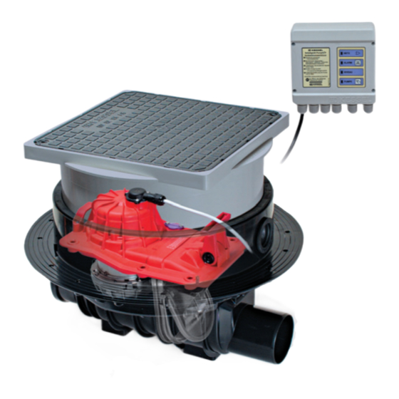
KESSEL - Pumpfix
For wastewater with or without sewage
Pumpfix
®
F
for concrete
slab installation
Installation
Service
of this unit should be carried out by a licensed professional
servicer.
Company / Telephone No.
INSTALLATION AND USER'S MANUAL
®
-F Backwater Valve with Sewage Pump
Pumpfix
®
F
for exposed pipe
installation
Article # 28100 S/X, 28125 S/X, 28150 S/X
Product Advantages
Backwater valve with integrated sewage pump
For sewage and greywater
Control unit with SDS (Self Diagnosis System)
Automatic closure during backwater
Manual closure lever
Simple access for maintenance
Rotatable, tiltable and vertically adjustable cover
(1.5 ton load class)
Also available for exposed / suspended pipe
Änderungsstand: 07/2008 HG
Sachnummer:
205-106
Subject to technical amendments
Advertisement
Table of Contents

Related Manuals for Kessel Pumpfix-F 28100 S


Summary of Contents for Kessel Pumpfix-F 28100 S
- Page 1 INSTALLATION AND USER’S MANUAL KESSEL - Pumpfix ® -F Backwater Valve with Sewage Pump For wastewater with or without sewage Article # 28100 S/X, 28125 S/X, 28150 S/X Product Advantages Backwater valve with integrated sewage pump For sewage and greywater...
-
Page 2: Table Of Contents
Table of Contents 1. Safety Instructions ......................page 2. General Areas of application ................page Contents of delivery ................page When to install the Pumpfix F ............page ® 3. Installation Installation in a concrete slab / floor..........page Deep installation in a concrete slab / floor ........page Installation subject to groundwater ........... - Page 3 Table of Contents 7. Problem Notification Notification during power use............page Notification of power failure............... page 8. Additional Functions Self Diagnosis System (SDS) ............page Battery life and replacement ............. page Battery function................. page Signalling device with auxiliary connection (optional) ....... page ......................
- Page 4 Use caution during installation, inspection, The internal backwater flap and the manual maintenance, use and repair of this product. closure lever must always have full range of Before placing the KESSEL Pumpfix ® F in motion. service, please carefully read and follow The Pumpfix ®...
-
Page 5: Areas Of Application
2. General 2.1 Areas of application body of the valve with cover and pump The Pumpfix ® F is designed to be installed Important: should be installed (the optical probe and in a downward sloped, vented, continous A requirement for trouble free operation is control unit should not be connnected) run drainage pipe. -
Page 6: Deep Installation In A Concrete Slab / Floor
The KESSEL Pumpfix DN 50 pipe as shown in Illustrations 2 and 5. ® F provides protection against the upward Grease and install the included rubber gas- Illus. -
Page 7: Installation Example
3. Installation ATTENTION: 3.5 Installation Example Make sure that no cables or other objects impair the movement of the manual closure lever or interfere with the Cellar drain, washing operation, inspection or maintenance of machines, sinks, Ž ‘ the valve. -
Page 8: Wall Mounting Of The Control Unit
4. Electrical connections 4.1 Wall mounting of the control unit As always, make sure the control unit is dis connected from the power supply before opening the cover. Unscrew the four screws located in each corner of the front of the control unit and open the cover. -
Page 9: Audible Signalling Device With Extension Cable (Optional)
4. Electrical connections tighten with the same two screws as seen in 4.6 Shortening the cables Illus. 12. (the optical probe is designed so The cables from the control unit to the that it can only be installed the proper way). Pumpfix ®... -
Page 10: Cable Extensions
4. Electrical connections 4.7 Cable extensions 4.7 Electrical connection plan The motor cable and the optical probe cable Illus. 14 for the Pumpfix ® F are delivered with a length of 5 meters. If requested the unit can be supplied with 15 meter cables instead of the standard 5 meter cable length. - Page 11 5. Initialization While the control unit is unplugged connect the two supplied 9-volt batteries which are al- ready located inside the control unit. Close cover control unit tighten the four screws. Plug in the control unit to a suitable power supply. The control unit will perform a basic systems check.
-
Page 12: Principle Functions
6. Operation 6.1 Principle Functions 3. Wastewater disposal during 1. Normal operation 2. Backwater operation backwater Cellar drain, washing machines, Cellar drain, washing machines, Cellar drain, washing machines, sinks, bathtubs, toilets sinks, bathtubs, toilets sinks, bathtubs, toilets During normal conditions the Pumpfix During times of backwater the Pumpfix F pro- ®... -
Page 13: Custom Pump Settings
6. Operation 6.2 Custom Pump Settings Setting the pumping times. If within 20 seconds the changes are not The Pumpfix ® F is delivered pre program- The Pumpfix ® F can be programmed to saved by pressing the ʻPUMPING / TEST med so that it can be installed and used adjust how long the pump runs. - Page 14 6. Operation Setting the ʻPump start delayʼ times. the pump start delay times press the ʻALAR- Setting to either ʻFinish Controlledʼ or ʻStart The Pumpfix ® F can be programmed to Mʼ button. Each time the ʻALARMʼ Controlledʼ modes. delay starting the pump after the optical sen- button is pressed, additional time will be sor has sensed wastewater.
-
Page 15: Alarms / Pump Test
6. Operation again turn on after the pump start delay time releasing the ʻALARMʼ and ʻPUMPING / 6.3 Alarms / Pump Test has elapsed. TEST PUMPʼ buttons the current Control setting can be determined by the blinking ALARM - The “Alarm” button located on the The Pumpfix ®... -
Page 16: Notification During Power Use
7. Problem notification During initialization and use the KESSEL control unit notifies the user of problems which can aid in finding easy solutions. 7.1 Notification during power use: Notification Problem Solution Tips ʻPOWERʼ LED and Battery is missing or defective. -
Page 17: Notification Of Power Failure
7. Problem notification 7.2 Notification of power failure: Notification Problem Solution Tips The Pumpfix F is not receiving The pump of the Pumpfix The ʻALARMʼ LED ® Reconnect to a suitable power supply ® blinks every two power (has been disconnected or a or wait for power failure to end. -
Page 18: Self Diagnosis System (Sds)
Batteries Pumpfix ® F automatically tests its pumping certified for use with the KESSEL Pumpfix ® system once per month. As part of this self F are Duracell 9 Volt Type MN 1604/6LR61 test, the pump will run for two seconds. If the (Requirement - 2). - Page 19 10. Technical Data Control Unit Fuse 10 Amp fuse Power 230 V AC / 50 Hz Power use in stand-by mode 17 mA Temperature limits 0°C + 40°C Splash Protection IP 54 (control unit) Protection Class 230 V AC, 16 A, cos w = 1 Power supply Potential free contact power supply 42 V DC / 0,5 A...
-
Page 20: Inspection
10. Inspection and Maintenance 10.1 Inspection only be completed by a licensed 10.3 Checking the pump The Pumpfix ® F should be inspected monthly professional servicer. The pump should be checked regularly. In by the owner or a professional servicer to the case of unusual noises during operation, insure that it is in proper operating condition. -
Page 21: Checking The Control Unit
10. Inspection and Maintenance 10.4 Checking the control unit 10.5 Malfunctions The batteries should be checked yearly and In the case of an undiagnosable malfunction of the Pumpfix ® F , please contact your replaced if necessary. If replacing the batteries make sure to install recommen- distributor or supplier. - Page 22 11. Replacement Parts 11.1 Detailed drawing 11.2 Replacement parts list Order Number 11. Cover with motor DN 100/125 205-046 12. Cover with motor DN 150 205-045 13. Pump housing upper section for DN 100, DN 125 models 205-032 14. Pump housing upper section for 6 DN 150 models 205-016 15.
- Page 23 12. Warranty 1. In the case that a KESSEL product is or replaced, the newly repaired or repla- 2. Wear and tear on a product will not be defective, KESSEL has the option of re- ced product shall receive a new warranty considered a defect.
- Page 24 E v e r y t h i n g f o r D r a i n a g e Solutions from a single source Backwater valves and cleanouts Polymer and cast iron drains Volatile liquid traps Lifting stations, pumps, warning and control units Rainwater management systems Grease, starch and oil / fuel...
Need help?
Do you have a question about the Pumpfix-F 28100 S and is the answer not in the manual?
Questions and answers