Kessel Aqualift F XL Instructions For Installation, Operation And Maintenance
Pumping station, dry set-up
Hide thumbs
Also See for Aqualift F XL:
- Installation and operating instructions manual (108 pages) ,
- Instructions for installation, operation and maintenance (208 pages) ,
- Installation and operating manual (168 pages)
Table of Contents
Advertisement
Available languages
Available languages
Quick Links
ANLEITUNG FÜR EINBAU, BETRIEB UND WARTUNG
KESSEL Pumpstation Aqualift F XL
- Trockene Aufstellung
Installation
der Anlage wurde durchgeführt von Ihrem Fachbetrieb:
Name/Unterschrift
Stand 2018/03
Inbetriebnahme
Datum
Einweisung
Ort
Produktvorteile
Für fäkalienfreies und
fäkalienhaltiges Abwasser
Trockene Aufstellung =
sauberer Arbeitsraum
3 m Grundwasser-
beständig
Schaltgerät mit
Selbstdiagnosefunktion
Stempel Fachbetrieb
D
Seite 1
GB
Page 41
F
Page 81
I
Pagina 121
NL Pagina 161
PL
Strona 201
Sach-Nr. 010-695
Advertisement
Chapters
Table of Contents

Related Manuals for Kessel Aqualift F XL


Summary of Contents for Kessel Aqualift F XL
- Page 1 ANLEITUNG FÜR EINBAU, BETRIEB UND WARTUNG KESSEL Pumpstation Aqualift F XL Seite 1 Page 41 - Trockene Aufstellung Page 81 Pagina 121 NL Pagina 161 Strona 201 Produktvorteile Für fäkalienfreies und fäkalienhaltiges Abwasser Trockene Aufstellung = sauberer Arbeitsraum 3 m Grundwasser- beständig...
-
Page 2: Table Of Contents
Schaltgerät montieren ....................... 15 KESSEL Tele-Control-Modem montieren ................. 15 Druckleitungsanschluss ....................15 Elektrische Anschlüsse und Anschlüsse Niveausensoren herstellen ....... 16 3.10 Erstinbetriebnahme ......................18 3.10.1 Schaltgerät initialisieren ....................18 3.10.2 KESSEL Tele-Control-Modem für Fehlermeldungen einrichten ........19 2 / 240 2018/03... - Page 3 3.10.3 Anpassung der Schaltpunkte für Lufteinperlung ............... 19 3.10.4 Funktionskontrolle ......................19 Betrieb Funktionen der Schalter ....................20 Einschalten ........................20 Display, Anzeigen / Informationen ..................20 Funktionen aller Tasten / Anzeigen ................... 21 Alarm Quittieren ........................ 21 Ausschalten ........................21 Einstellungen Bedienmenü...
-
Page 4: Einleitung
Haben Sie Fragen? Wir freuen uns auf Ihre Kontaktaufnahme. Produktbeschreibung, allgemein Die KESSEL Pumpstation Aqualift F XL (im folgenden Pumpstation benannt) ist für das Abpumpen von fäkalienfreiem und fäkalienhaltigem Abwasser vorgesehen. Der Abwasserbehälter nimmt die Pumpe(n) und den/die Niveausensor(en) auf. Die Baugruppen sind auf das mitgelieferte KESSEL-Schaltgerät abgestimmt. Die Pumpstation wird mit unterschiedlichen Abwasserpumpen ausgeliefert. -
Page 5: Allgemeine Hinweise Zu Dieser Betriebs- Und Wartungsanleitung
Einleitung Allgemeine Hinweise zu dieser Betriebs- und Wartungsanleitung Diese Betriebs- und Wartungsanleitung ist nur in Verbindung der Betriebs- und Montageanleitung des Schaltgeräts Aqualift F Comfort 400V (Sach-Nr. 010-532), bzw. Aqualift F Comfort 230 V (Sach-Nr. 010-910) vollständig. Verwendete Symbole und Legenden <1>... -
Page 6: Funktionsprinzip
Einleitung Funktionsprinzip normale Einbauhöhe Abb. [1] niedrigste Einbauhöhe Abb. [2] 6 / 240 2018/03... -
Page 7: Typenschild
Einleitung Typenschild Informationen auf dem Typenschild Bezeichnung der Anlage Material-Nummer der Anlage Anschlussspannung und Anschlussfrequenz Aqualift Hydraulische Daten xxxxx U = xxxV xxHz I = x,xA P1 = x,xkW Allgemeine Daten Q = xxm³/h H = xxm S3 xx% ED IP xx (3mWS /48h) Ser.Nr. -
Page 8: Lieferumfang
Einleitung Lieferumfang Schaltgerät mit eigener Montageanleitung Betriebs- und Wartungsanleitung Anschlussplan, im Gehäusedeckel des Schaltgerätes Befestigungsmaterial für Schaltgerät Bohrschablone für Schaltgerät Anlagenbehälter (Bodenelement des Schachtsystems) Schachtsystem, bestehend aus verschiedenen Elementen mit eigener Montageanleitung (ohne Abbildung) Abwasserpumpe(n) 2 Stück 45°-Bögen DN 150 mit Rohrdurchführungsdichtung (ohne Abb.) Abb. -
Page 9: Baugruppen Und Funktionsmerkmale
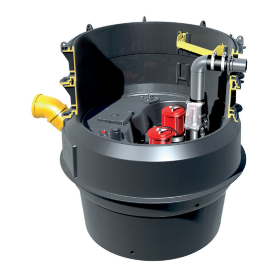
Einleitung Baugruppen und Funktionsmerkmale Abb. [6] Abb. [7] normale Einbauhöhe niedrige Einbauhöhe Schaltgerät Anlagenbehälter (Bodenelement des Schachtsystems) Typenschild Abwasserpumpen Druckleitung Rückflussverhinderer mit Absperrschieber Zulauf Niveaufühler (Drucksensor) Anschluss Entlüftungsleitung 2018/03 9 / 240... -
Page 10: Sicherheit
Sicherheit Sicherheit Bestimmungsgemäße Verwendung Die Pumpstation dient als Entwässerungsanlage für fäkalienhaltiges und –freies, häusliches und gewerbliches Abwasser, montiert in einem begehbaren KESSEL-Schachtsystem, unterschiedlicher Höhe und Ausprägung. Personalauswahl und -qualifikation Personen, die die Pumpstation montieren, müssen – mindestens 18 Jahre alt sein. – für die jeweiligen Tätigkeiten ausreichend geschult und qualifiziert sein. -
Page 11: Gefahren, Die Vom Produkt Ausgehen
Sicherheit Gefahren, die vom Produkt ausgehen 2.4.1 Gefahr durch besondere Örtlichkeit / Umgebungsbedingungen Gefahr durch giftige und gesundheitsgefährdende Dämpfe, Gase und Stoffe (z. B. Bakterien, Viren). Befindet sich die Pumpstation in einem Schacht, sind darin notwendige Arbeiten ausschließlich durch Fachpersonal (Siehe 2.2) durchzuführen. 2.4.2 Gefahr durch elektrischen Schlag bei abgeschraubtem Stecker Am Schaltgerät (nur 230V-Ausführung) besteht die Gefahr eines elektrischen Stromschlags, wenn einer der Stecker für die Stromversorgung der Pumpen demontiert ist. -
Page 12: Gefahr Durch Hitze
Sicherheit 2.4.7 Gefahr durch Hitze Gefahr von Verbrennungen beim Berühren heißer Oberflächen. Abwasserpumpen entwickeln bei längerem Lauf eine hohe Temperatur an der Gehäuseoberfläche. Schutzausrüstung (Handschuhe) tragen oder Pumpen entsprechend abkühlen lassen. 2.4.8 Gefahr durch unerwartetes Anlaufen einer Pumpe Ist die Pumpstation nicht vom Netz getrennt, kann jede Pumpe unvermittelt anlaufen. Pumpen ausschließlich durch Fachpersonal und bei freigeschalter sowie gegen unbeabsichtigtes Wiedereinschalten abgesicherter Ablage ausbauen. -
Page 13: Montage
Montage Montage Gefahr durch giftige und gesundheitsgefährdende Dämpfe, Gase und Stoffe (z. B. Bakterien, Viren). Alle an der Pumpstation notwendige Arbeiten ausschließlich durch Fachpersonal (Siehe 2.2) durchführen. Allgemeines zur Montage Die Pumpstation wird entsprechend den auf einer Baustelle üblichen Bauabschnitten zu unterschiedlichen Zeitpunkten montiert und in Betrieb genommen. -
Page 14: Abwasserpumpen(N) Montieren
Montage Abwasserpumpen(n) montieren • Abwasserpumpe(n) mit den Schrauben <1> befestigen (Anzugsmoment 7Nm). Abb. [9] Abb. [10] normale Einbauhöhe niedrige Einbauhöhe 3.4.1 Pumpenentnahme aus dem Schacht Zur leichteren Entnahme der Pumpe aus dem Schacht den Stopfen <A> aus Pumpengehäuse entfernen und Ringschraube <B>... -
Page 15: Kleinkompressor Zur Lufteinperlung Montieren
Luftschlauch gemäß der mitgelieferten Montageanleitung anschließen. Schaltgerät montieren Schaltgerät gemäß der dem Schaltgerät beiliegenden Anleitung montieren. KESSEL Tele-Control-Modem montieren (Option) KESSEL Tele-Control-Modem gemäß der diesem Schaltgerät beiliegenden Anleitung montieren. Druckleitungsanschluss Der Druckleitungsanschluss ist in PE DN 80 (DA= 90 mm) SDR 17 ausgeführt. KESSEL empfiehlt den Anschluss von handelsüblichen PE-HD-Elektroschweißmuffen. -
Page 16: Elektrische Anschlüsse Und Anschlüsse Niveausensoren Herstellen
Montage Elektrische Anschlüsse und Anschlüsse Niveausensoren herstellen Sicherstellen, dass das Schaltgerät während den Montagearbeiten von der Spannungsversorgung getrennt ist. Gefahr von elektrischem Schlag bei unbeabsichtigten Berühren abgeschraubter Steckverbindungen (z.B. durch Kinder). Sicherstellen, dass alle elektrischen Anschlussverbindungen - sofern vorhanden - wie abgebildet befestigt werden (Anzugsmoment). - Page 17 Montage • Pumpe(n) an den Steck- und Schraubverbindungen <b und c> anschließen. Abb. [12] • Anschlüsse der Niveaufühler wie folgt herstellen. Anschluss (Abb. [12]) Farbkodierung Kabel Alarmsensor Drucksensor • Alle Kabel der elektrischen Komponenten und die Leitung des Drucksensors sicher verlegen. Empfehlung: Befestigung an den an der Schachtwand montierbaren Kabelrohrschellen.
-
Page 18: Erstinbetriebnahme
Montage 3.10 Erstinbetriebnahme Ein Trockenlauf der Abwasserpumpe(n) ist unbedingt zu vermeiden, sie könnten beschädigt werden. Niemals Abwasserpumpen einschalten, wenn der Abwasserbehälter nicht mindestens bis zum Pegelstand Minimum befüllt ist. 3.10.1 Schaltgerät initialisieren • Schaltgerät mit Netzspannung versorgen, die Initialisierung beginnt. Während für ca. 4 Sekunden die LED‘S leuchten, werden die elektrischen Bauteile überprüft, die Batterie für die Netzausfall-Meldung aktiviert und das Menü... -
Page 19: Kessel Tele-Control-Modem Für Fehlermeldungen Einrichten
Montage 3.10.2 KESSEL Tele-Control-Modem für Fehlermeldungen einrichten (Option) Im Menüpunkt 3.9 kann eingestellt werden, welche Ereignisse der Pumpstation an welche SMS- Empfänger gesendet werden. 3.10.3 Anpassung der Schaltpunkte für Lufteinperlung (Option) Sofern ein Kleinkompressor für die Lufteinperlung installiert ist, folgende Anpassung vorgenommen: •... -
Page 20: Betrieb
Betrieb Betrieb Alle Rückflussverhinderer mit Absperrschieber müssen während dem Betrieb der Pumpstation geöffnet und verriegelt sein (nach oben herausgezogen, siehe <25> auf Seite 9). Funktionen der Schalter Einschalten • Hauptschalter <28> in Position I (ON) drehen, nach erfolgreichem Systemtest erscheinen im Display <29> die Anlageninformationen und die grüne LED <30> leuchtet, das Schaltgerät ist betriebsbereit. Abb. -
Page 21: Funktionen Aller Tasten / Anzeigen
Betrieb Funktionen aller Tasten / Anzeigen Pumpe 1 Pumpe 2 Alarm Betriebsbereit Pfeil oben Blättern im Menü Pfeil unten Blättern im Menü Löschen einer Eingabe, zurück Alarm Quittierung des akustischen Alarms Pumpe / Test Pumpe 1 EIN / AUS Bestätigen einer Eingabe, nächste Ebene Pumpe / Test Pumpe 2 EIN / AUS... -
Page 22: Einstellungen Bedienmenü
Einstellungen Bedienmenü Einstellungen Bedienmenü Allgemeines Die Menüsteuerung des Schaltgeräts verfügt über einen Bedien- und einen Standbymodus. Im Bedienmodus können die Systemeinstellungen über das Display angezeigt und eingestellt werden. Erfolgt über einen Zeitraum von ca. 60 Sekunden keine Betätigung einer der Tasten, wird automatisch der Standbymodus aktiviert, die Hintergrundbeleuchtung des Displays ist dann ausgeschaltet Navigationstasten für das Menü... -
Page 23: Bedienmenü
Einstellungen Bedienmenü Navigation im Menü Aktion Bedienung Menüpunkt auswählen Pfeil oben / Pfeil unten, ausgewählter Menüpunkt wird invertiert dargestellt Menüpunkt zur Bearbeitung OK, ist ein Menü-Unterpunkt vorhanden, wird dieser invertiert dargestellt. aktivieren Einstellwert anzeigen bearbeiten OK, Wert wird angezeigt bzw. zur Einstellung invertiert dargestellt Menü... - Page 24 Einstellungen Bedienmenü Nummer Menü Einheit Wertebereich zuletzt aufgetretenes E&F bis zu 256 E&Fs davor aufgetretenes E&F davor aufgetretenes E&F Steuerungstyp Wartungstermin 1.4.1 Letzte Wartung TT.MM.JJJJ 1.4.2 Nächste Wartung TT.MM.JJJJ akt. Messwerte 1.5.1 Netz-Spannung 1.5.2 Netz-Strom 1.5.3 Batterie-Spannung 1.5.4 Füllstand 0…999 Parameter 1.6.1 Höhe Stauglocke...
- Page 25 Einstellungen Bedienmenü Nummer Menü Einheit Wertebereich Kalibrierung Einstellungen Parameter 3.1.1 Höhe Stauglocke 0...999 3.1.2 Einschaltsperre 0...999 3.1.3 Messbereich 0...999 3.1.4 EIN1-Niveau 0…999 3.1.5 EIN2-Niveau 0...999 3.1.6 AUS1-Niveau 0...999 3.1.7 Alarm-Niveau 0...999 3.1.8 Ein-Verzögerung 0…999 3.1.9 Nachlaufzeit 0...999 3.1.10 Grenzlaufzeit 0...999 3.1.11 Grenzlaufzahl 0...999999...
- Page 26 Einstellungen Bedienmenü Nummer Menü Einheit Wertebereich 3.6.14 F AP 501 Mono LW 1000 3.6.15 Sonder-Pumpstation ohne ATEX 3.6.16 Sonder-Pumpstation ATEX 3.6.17 F ATEX Duo 3.6.18 F Duo 3.6.19 F AP 501 Duo LW 800 3.6.20 F AP 501 Duo LW 1000 3.6.21 Sonder-Pumpstation ohne ATEX 3.6.22...
- Page 27 Einstellungen Bedienmenü Nummer Menü Einheit Wertebereich 3.10.13 Italiano 3.10.14 Polski 3.10.15 Nederlands 3.11 Rücksetzen 3.12 Experten-Modus 3.12.1 Netz-Einschaltverzögerung 0 - 99 3.12.2 Batterieüberwachung ein/aus 3.12.3 Schwelle Batterie 0 - 18,0 3.12.4 Alternierender Betrieb ein/aus 3.12.5 Max. Schaltspiele 1000 - 999.999 Nach Reset oder bei Erstinitialisierung werden nach dem Einschalten die folgenden Einstellungen abgefragt: 3.10 Sprache...
- Page 28 Einstellungen Bedienmenü Nummer Menü Einheit Wertebereich 3.6.20 F AP 501 Duo LW 1000 3.6.21 Sonder-Pumpstation ohne ATEX 3.6.22 Sonder-Pumpstation ATEX Leistungsgrösse 3.7.1 SPF 1500 3.7.2 SPF 3000 3.7.3 SPF 4500 3.7.4 SPF 5500 3.7.5 TPF 1,9kW 3.7.6 TPF 1,3 kW 3.7.7 Ama Porter 3.7.8...
-
Page 29: Wartung
Wartung Wartung Vor einem Öffnen von Gehäuseabdeckungen, Steckern und Kabeln (auch an den potentialfreien Kontakten) sind diese spannungsfrei zu machen. Arbeiten an elektrischen Bauteilen dürfen nur von Fachpersonal (Siehe 2.2) durchgeführt werden. Allgemeine Hinweise für die Wartung Bei Wartungsarbeiten darf weder auf elektrische Komponenten, Leitungsverbindungen oder Kabel gestiegen werden. -
Page 30: Wartungsvorbereitung
Wartung Wartungsvorbereitung Muss der Anlagenbehälter entleert werden, kann das über ein in der Entlüftungsleitung installiertes Revisionsstück (2) erfolgen. Hierzu eine geeignete Pumpe mit Schlauch (1) verwenden. Abb. [18] 30 / 240 2018/03... -
Page 31: Wartungskarte
Wartung 6.3.1 Wartungskarte Inspektion-/Wartung Pumpstation Aqualift F XL Objektbezeichnung Objekt Strasse PLZ, Ort Kontakt Anlagenvariante Mono Seriennummer Pumpentyp Sicherheitshinweise für die Wartung Vor dem Öffnen des Abwasserbehälters für ausreichende Belüftung des Raumes sorgen. Zündquellen fern halten und nicht rauchen. Sicherstellen, dass die Pumpe(n) Umgebungstemperatur angenommen haben. - Page 32 Wartung LNr. Prüfung Erledigungsvermerk nein Druckschalter Tauchrohr entnehmen und reinigen, Pumpe entnehmen und Behälter reinigen Optische Kontrolle Druckschalter Steigende Verlegung der Steuerleitung (stetig steigend) Tauchrohr Tauchrohr entnehmen und reinigen Anschluss Lutschlauch prüfen Klemmring und Verschraubung auf richtigen Sitz prüfen Batterie oder Akku messen Wert IST________ Pumpe Isolationswiderstand messen...
- Page 33 Wartung Ergebnisbericht Verwendete Ersatzteile Verbleib der ausgetauschten Ersatzteile Beim Auftraggeber Beim Leistungsempfänger Anlage betriebsbereit an Kunden übergeben Werkskundendienst/Fachmann Stempel Ort, Datum Unterschrift KESSEL AG/Werkskundendienst Name in Druckbuchstaben/Unterschrift Auftraggeber 2018/03 33 / 240...
-
Page 34: Fehlersuche
Fehlersuche Fehlersuche Anzeigetext Netzausfall Mögliche Ursache Abhilfemaßnahme Sondenfehler Kabel prüfen und ggf. tauschen, Sonde Kabel Schaltgerät-Alarmsonde (optional) unterbrochen prüfen und ggf. tauschen Druckfehler Verbindungsschlauch Schaltgerät- Verbindungsschlauch prüfen und ggf. Drucksensor undicht tauschen Batteriefehler Batterie fehlt, ist defekt oder Batterieanschluss prüfen, ggf. Batterie Spannung kleiner 13,5V. - Page 35 Fehlersuche Druckabfall Schlauch an der Verschraubung zum Dichtheit des Drucksensor-Systems Tauchrohr (oder Tauchglocke) bzw. prüfen Schaltgerät undicht. Relaisschaltspiele 1 bzw. 2 Maximale Schaltspiele überschritten Kann quittiert werden. Kundendienst informieren. Fehler erscheint nach weiteren 1000 Schaltspielen Grenzlaufzeit 1 bzw. 2 Pumpe läuft zu lange pro Anlagenauslegung prüfen ggf.
-
Page 36: Technische Daten
Technische Daten Technische Daten Pumpen Pumpe 1400 1500 3000 4500 Gewicht [kg]* Leistung P1 [kW] Leistung P2 [kW] Drehzahl [U/min] 1370 1415 2845 2845 Betriebsspannung [V] 50 Hz Nennstrom [A] Förderleistung max. [m³/h] Förderhöhe max. [m] Förderguttemperatur max. [°C] Schutzart IP68 (3m Ws/48h) Schutzklasse Motorschutz... -
Page 37: Förderstrom
Technische Daten Förderstrom Förderstrom Q [m³/h] bei Förderhöhe H [m] Pumpe H [m] SPF.. 1400 * 26,1 12,5 Q [m³/h] 1500 * 37,5 28,2 15,8 Q [m³/h] 3000 * 40,1 34,4 28,3 22 15,6 8,8 Q [m³/h] 4500 * 53,4 48,4 42,9 37,5 30 22,5 13,1 Q [m³/h] * S3/S1 ** S3... -
Page 38: Leistungserklärung /Dop
Leistungserklärung /DOP Leistungserklärung /DOP 38 / 240 2018/03... - Page 39 Leistungserklärung /DOP 2018/03 39 / 240...
- Page 40 Führend in Entwässerung Privater Wohnungsbau ohne Kanalanbindung 1 2 3 4 1 2 3 4 Öffentlicher Bau z.B. Krankenhaus Öffentlicher Bau z.B. Freizeitanlagen 1 2 3 4 Gewerblicher Bau z.B. Hotel Gewerblicher Bau z.B. Industriebau 2 3 5 Gewerblicher Bau z.B.
- Page 41 INSTRUCTIONS FOR INSTALLATION, OPERATION AND MAINTENANCE KESSEL Pumping station Aqualift F XL - Dry set-up Product advantages For wastewater with and without sewage Dry set-up = clean working space Resistant to groundwater up to 3 m Control unit with self-...
- Page 42 Pressure Pipe Connection ....................55 Establishing electrical connections and connections to the level sensors ......56 3.10 Initial operation ......................... 58 3.10.1 Initialising the control unit ....................58 3.10.2 Setting up the KESSEL tele-control modem for fault messages ........58 42 / 240 2016/05...
- Page 43 3.10.3 Adapting the switching points for air bubble formation ............. 59 3.10.4 Functional check ....................... 59 Operation Switch functions ........................ 60 Switching on ........................60 Displays / information ....................... 60 Functions of all keys / displays ..................61 Acknowledging the alarm ....................61 Switching off ........................
-
Page 44: Introduction
Have you got any questions? We look forward to you getting in touch. Product description, general The KESSEL pumping station Aqualift F XL (referred to as „pumping station“ from here onwards) has been designed for pumping off wastewater with and without sewage. The wastewater tank houses the pump(s) and the level sensor(s). -
Page 45: General Instructions On Using These Operating And Maintenance Instructions
Introduction General instructions on using these operating and maintenance instructions These operating and maintenance instructions are only complete in combination with the operating and maintenance instructions of the Aqualift F Comfort 400 V (part no. 010-532) or Aqualift F Comfort 230 V (part no. 010-910) Symbols and legends used <1>... -
Page 46: How It Works
Introduction How it works normal installation height Ill. [1] minimum installation height Ill. [2] 46 / 240 2016/05... -
Page 47: Type Plate
Introduction Type plate Information on the type plate Name of the system Material number of the sytem Connection voltage and connection frequency Aqualift Hydraulic data xxxxx U = xxxV xxHz I = x,xA P1 = x,xkW General data Q = xxm³/h H = xxm S3 xx% ED IP xx (3mWS /48h) -
Page 48: Scope Of Supply
Introduction Scope of supply Control unit with separate installation instructions Operating and maintenance instructions Connection diagram, in the control unit housing cover Fastening material for the control unit Drilling template for the control unit System tank (base element of the chamber system) Chamber system, comprising different elements with suitable installation instructions (not shown) Wastewater pump(s) -
Page 49: Component Assemblies And Functional Properties
Introduction Component assemblies and functional properties Ill. [6] Ill. [7] normal installation height low installation height Control unit System tank (base element of the chamber system) Type plate Wastewater pumps Pressure pipe Backwater preventer with shut-off valve Inlet Level sensor (pressure sensor) Connection for vent pipe 2016/05 49 / 240... -
Page 50: Safety
Correct use The pumping station is used as a draining system for wastewater with and without sewage, domestic and industrial wastewater, installed in an accessible KESSEL chamber system of differing heights and designs. Staff selection and qualification Persons who install the pumping station must –... -
Page 51: Risks Caused By The Product
Safety Risks caused by the product 2.4.1 Risk caused by special location / ambient conditions Risk caused by toxic and hazardous vapours, gases and substances (e. g. bacteria, viruses). If the pumping station is located in an inspection chamber, any necessary work must always be done by specialist staff (see 2.2). -
Page 52: Risk Caused By Heat
Safety 2.4.7 Risk caused by heat Risk of burning by touching hot surfaces. When in operation for longer periods, wastewater pumps develop a high temperature on the housing surface. Wear protective equipment (gloves) or allow the pumps to cool down accordingly. -
Page 53: Installation
Installation Installation Risk caused by toxic and hazardous vapours, gases and substances (e. g. bacteria, viruses). Always have any necessary work on the pumping station done by specialist staff (see 2.2). General points related to installation The pumping station is installed and put into operation at different times according to the usual construction phases on a building site. -
Page 54: Installing The Wastewater Pump(S)
Installation Installing the wastewater pump(s) • Fix the wastewater pump(s) in place using the screws <1> (tightening torque 7 Nm). Ill. [9] Ill. [10] normal installation height low installation height 3.4.1 Pump removal from chamber For easy / safe removal of the pump from the pump chamber, remove plug <A> from the pump housing and screw in the eye bolt <B>... -
Page 55: Installing The Small Compressor For Air Bubble Formation
Install the control unit in accordance with the instructions enclosed with the unit. Installing the KESSEL tele-control modem (Option) Install the KESSEL tele-control modem in accordance with the instructions enclosed with this unit. Pressure Pipe Connection Connect to PE DN 80 (OD = 90 mm) SDR 17 pressure pipe. -
Page 56: Establishing Electrical Connections And Connections To The Level Sensors
Installation Establishing electrical connections and connections to the level sensors Make sure that the control unit is disconnected from the power supply during installation work. Risk of electric shock caused by the unintentional touching of plug-type connections which have been screwed off (e.g. - Page 57 Installation • Connect pump(s) to the plug-type connections <b and c>. Ill. [12] • Establish connections for the level sensor as follows. Connection (Fig. [12]) Colour coding cable Alarm sensor Pressure sensor • Route all cables for the electric components and the pressure sensor line safely. Recommendation: attachment to the cable pipe clamps that can be mounted on the wall of the inspection chamber.
-
Page 58: Initial Operation
System information appears, initialisation is complete. 3.10.2 Setting up the KESSEL tele-control modem for fault messages (Option) In menu item 3.9, it is possible to define which incidents of thepump stationare to be sent to which text message recipient. 58 / 240... -
Page 59: Adapting The Switching Points For Air Bubble Formation
Installation 3.10.3 Adapting the switching points for air bubble formation (Option) If a small compressor for air bubble formation is installed, it must be adapted as follows: • Make sure that the system tank is full. • Switch the small compressor off. •... -
Page 60: Operation
Operation Operation All backwater preventers with shut-off valves must be opened and locked during operation of the pumping station (pulled up and out, see <25> on page 49). Switch functions Switching on • Turn the main switch <28> to position I (ON), following a successful system test the system information appears in the display <29>... -
Page 61: Functions Of All Keys / Displays
Operation Functions of all keys / displays Pump 1 Pump 2 Alarm Ready for operation Cursor up Scrolling in the menu Cursor down Scrolling in the menu Deletion of an entry, back Alarm Acknowledge the acoustic alarm Pump / Test Pump 1 ON / OFF Confirmation of an entry, next level Pump / Test... -
Page 62: Operating Menu Settings
Operating menu settings Operating menu settings General information The control unit menu prompting has an operating and a standby mode. In operating mode the system settings can be displayed and adjusted on the display. If over a period of approx. 60 seconds none of the keys are pressed, standby mode is activated automatically, the background lighting of the display is then switched off. -
Page 63: Operation Menu
Operating menu settings Navigation in the menu Action Operation Select menu item Cursor up / cursor down, selected menu item is shown inverted Activate menu point for editing OK. If a menu sub-item exists, this is shown inverted. Display or edit set value OK, value is displayed or shown inverted for setting Quit menu ESC, leave current level, moves up a level... - Page 64 Operating menu settings Number Menu Unit Value range I&F previous to that Control unit type Maintenance date 1.4.1 Last maintenance DD.MM.YYYY 1.4.2 Next maintenance DD.MM.YYYY Curr. measured values 1.5.1 Mains voltage 1.5.2 Mains power 1.5.3 Battery voltage 1.5.4 Filling level 0…999 Parameters 1.6.1...
- Page 65 Operating menu settings Number Menu Unit Value range Settings Parameters 3.1.1 Height of immersion pipe 0...999 3.1.2 Switch lock 0...999 3.1.3 Measuring range 0...999 3.1.4 ON1 level 0…999 3.1.5 ON2 level 0...999 3.1.6 OFF1 level 0...999 3.1.7 Alarm level 0...999 3.1.8 On delay 0…999...
- Page 66 Operating menu settings Number Menu Unit Value range 3.6.14 F AP 501 Mono LW 1000 3.6.15 Special pumping station without ATEX 3.6.16 Special pumping station ATEX 3.6.17 F ATEX Duo 3.6.18 F Duo 3.6.19 F AP 501 Duo LW 800 3.6.20 F AP 501 Duo LW 1000 3.6.21...
- Page 67 Operating menu settings Number Menu Unit Value range 3.10.10 Deutsch 3.10.11 English 3.10.12 Français 3.10.13 Italiano 3.10.14 Polski 3.10.15 Nederlands 3.11 Reset 3.12 Expert mode 3.12.1 Power-up delay 0 - 99 3.12.2 Battery monitoring on/off 3.12.3 Battery threshold 0 - 18.0 3.12.4 Alternating operation on/off...
- Page 68 Operating menu settings Number Menu Unit Value range 3.6.15 Special pumping station without ATEX 3.6.16 Special pumping station ATEX 3.6.17 F ATEX Duo 3.6.18 F Duo 3.6.19 F AP 501 Duo LW 800 3.6.20 F AP 501 Duo LW 1000 3.6.21 Special pumping station without ATEX...
-
Page 69: Maintenance
Maintenance Maintenance Before housing covers, plugs and cables (including those on potential-free contacts) are opened they must be switched voltage-free. Work on electrical components may only be carried out by specialist staff (see 2.2). General maintenance information No climbing on electrical components, pipe connections or cables during maintenance work. Risk caused by toxic and hazardous vapours, gases and substances (e. -
Page 70: Preparing For Maintenance Work
Maintenance Preparing for maintenance work If the system tank has to be emptied, this can be done via a revision coupler (2) installed in the vent pipe. Use a suitable pump with hose (1) for this purpose. Ill. [18] 70 / 240 2016/05... -
Page 71: Maintenance Card
Maintenance 6.3.1 Maintenance card Inspection/maintenance pumping station Aqualift F XL Name of the building Building Street Postcode, city Contact System variant Mono Serial number Pump type Maintenance safety notes Before opening the wastewater tank, ensure the room is sufficiently ventilated. Keep sources of ignition away and do not smoke. - Page 72 Maintenance Test Done record Remove the immersion pipe and clean it Check the air hose connection Check the clamping ring and screw attachment for a correct fit Measure battery or rechargeable battery value ACTUAL____________ Pump Measure insulation resistance value ACTUAL________ Switch the power on again Pump current consumption Readiness for operation...
- Page 73 Whereabouts of the spare parts replaced At the client‘s At the service customer‘s System ready for operation and handed over to the customer Stamp Factory Customer Service/Technician Place, date Signature KESSEL AG/Factory Customer Service Name in printed letters/Signature of client 2016/05 73 / 240...
-
Page 74: Troubleshooting
Troubleshooting Troubleshooting Display text power outage Possible cause Remedial measure Probefault Cable interrupted between control unit Check cable and replace if necessary, and alarm probe (option) check probe and replace if necessary. Pressure fault Connection hose control unit-pressure Check the connection hose and sensor leaking replace if necessary Battery fault... - Page 75 Troubleshooting Pressure loss Hose on the screw fitting to the Check airtightness of the pressure immersion pipe (or plunger) or control sensor system unit leaking. Relay operating cycles 1 or 2 Maximum operating cycles exceeded Can be acknowledged. Inform Customer Services. Fault appears after a further 1000 operating cycles Max run time 1 or 2 Pump is running too long per pumping...
-
Page 76: Technical Data
Technical data Technical data Pumps Pump 1400 1500 3000 4500 Weight [kg]* Capacity P1 [kW] Capacity P2 [kW] Speed [rpm] 1370 1415 2845 2845 Operating voltage [V] 50 Hz Nominal current [A] Max. pumping capacity [m³/h] Max. pumping height [m] Max. -
Page 77: Pumping Flow
Technical data Pumping flow Pumping flow Q [m³/h] at pumping height H [m] Pump H [m] SPF.. 1400 * 26.1 12.5 Q [m³/h] 1500 * 37.5 28.2 15.8 Q [m³/h] 3000 * 40.1 34.4 28.3 22 15.6 8.8 Q [m³/h] 4500 * 53.4 48.4 42.9 37.5 30 22.5 13.1 Q [m³/h]... -
Page 78: Declaration Of Conformity
Declaration of conformity Declaration of conformity 78 / 240 2016/05... - Page 79 Declaration of conformity 2016/05 79 / 240...
- Page 80 Leading in Drainage Private homes without public sewage connection 1 2 3 4 1 2 3 4 Public buildings (e.g. hospital) Public buildings (e.g. leisure facility) 1 2 3 4 Commercial buildings (e.g. hotel) Commercial buildings (e.g. industrial / manu- facturing facilities) 2 3 5 Commercial buildings...
- Page 81 INSTRUCTIONS DE POSE, D‘UTILISATION ET DE MAINTENANCE KESSEL Poste de pompage Aqualift F XL - installation sèche Avantages du produit Pour eaux grises et eaux vannes Installation sèche = espace de travail propre Étanche aux eaux souterraines jusqu‘à 3 mètres Gestionnaire avec fonction d‘autodiagnostic...
- Page 82 Montage du compresseur de faible puissance pour le barbotage à l‘air ......95 Montage du gestionnaire ....................95 Montage du modem de télécontrôle KESSEL ..............95 Raccord capteur de pression .................... 95 Réalisation des connexions électriques et des raccordements des capteurs de niveau .. 96...
- Page 83 Première mise en service ....................98 3.10.1 Initialisation du gestionnaire ..................... 98 3.10.2 Configuration du modem de télécontrôle KESSEL spécifique aux messages d‘erreur ..99 3.10.3 Adaptation des points de commutation du barbotage à l‘air ..........99 3.10.4 Contrôle du fonctionnement ....................99 Fonctionnement Fonctions des interrupteurs ....................
-
Page 84: Introduction
Chère cliente, Cher client, Nous vous félicitons de votre achat d‘un produit KESSEL. Ce produit sera certainement en mesure de répondre à toutes vos attentes. Nous vous souhaitons une mise en place sans faille et réussie. Nous tentons de maintenir un niveau de qualité aussi élevé que possible de nos produits et avons évidemment besoin de votre collaboration. -
Page 85: Informations D'ordre Général Concernant Ces Instructions D'utilisation Et De Maintenance
Introduction Informations d‘ordre général concernant ces instructions d‘utilisation et de maintenance Ces instructions d‘utilisation et de maintenance ne sont complètes qu‘en combinaison avec les instructions d‘utilisation et de montage du gestionnaire Aqualift F Comfort 400 V (Référence 010-532) ou Aqualift F Comfort 230 V (Référence 010-910. -
Page 86: Principe De Fonctionnement
Introduction Principe de fonctionnement hauteur de pose normale Fig. [1] hauteur de pose la plus basse Fig. [2] 86 / 240 2018/03... -
Page 87: Plaque Signalétique
Introduction Plaque signalétique Informations figurant sur la plaque signalétique Désignation du installation Numéro du matériau du installation Tension et fréquence d‘alimentation Aqualift Donnes hydrauliques xxxxx U = xxxV xxHz I = x,xA P1 = x,xkW Données d‘ordre général Q = xxm³/h H = xxm S3 xx% ED IP xx (3mWS /48h) -
Page 88: Fournitures
Introduction Fournitures Gestionnaire avec de propres instructions de montage Instructions de service et de maintenance Schéma de raccordement dans le couvercle du boîtier du gestionnaire Matériel de fixation du gestionnaire Gabarit de perçage pour le gestionnaire Bac collecteur (élément de base du système de regard) Système de regard composé... -
Page 89: Sous-Groupes Et Éléments Fonctionnels
Introduction Sous-groupes et éléments fonctionnels Fig. [6] Fig. [7] hauteur de pose normale basse hauteur de pose Gestionnaire Bac collecteur (élément de base du système de regard) Plaque signalétique Pompes d‘assainissement Conduite de refoulement Dispositif antireflux avec vanne d‘arrêt Entrée Détecteur de niveau (capteur de pression) Raccord de la conduite de purge d‘air 2018/03... -
Page 90: Sécurité
Le poste de pompage sert de système d‘assainissement pour les eaux vannes et eaux grises, eaux domestiques et industrielles ; il est monté dans un système de regard KESSEL à ouverture de visite praticable et disponible de différentes hauteurs et formes. -
Page 91: Risques Liés Au Produit
Sécurité Risques liés au produit 2.4.1 Risque lié à des lieux particuliers / aux conditions ambiantes Risque lié aux vapeurs, gaz et substances toxiques ou nuisible à la santé (p. ex. les bactéries, virus). Les travaux à effectuer sur un poste de pompage logé dans un regard demeurent réservés au domaine de compétence exclusif de personnes qualifiées (voir 2.2). -
Page 92: Risque Lié À La Chaleur
Sécurité 2.4.7 Risque lié à la chaleur Risque de brûlures au contact des surfaces chaudes Les pompes d‘assainissement développent une température élevée à la surface du carter après un fonctionnement de longue durée. Porter un équipement de protection (des gants) ou patienter jusqu‘au refroidissement des pompes. 2.4.8 Risque lié... -
Page 93: Montage
Montage Montage Risque lié aux vapeurs, gaz et substances toxiques ou nuisible à la santé (p. ex. les bactéries, virus). Tous les travaux à effectuer sur un poste de pompage demeurent réservés au domaine de compétence exclusif de personnes qualifiées (voir 2.2). Conseils de montage d‘ordre général La pose, le montage et la mise en service du poste de pompage sont effectués le moment donné... -
Page 94: Montage De La/Des Pompe/S D'assainissement
Montage Montage de la/des pompe/s d‘assainissement • Fixer la/les pompe/s d‘assainissement avec les vis <1> (couple de serrage 7 Nm). Fig. [9] Fig. [10] hauteur de pose normale basse hauteur de pose 3.4.1 Extraire la pompe du regard Pour faciliter l’extraction de la pompe du regard, Tirer sur le bouchon <A> de la pompe et tourner l’anneau <B> (M8 DIN 580, en option). -
Page 95: Montage Du Compresseur De Faible Puissance Pour Le Barbotage À L'air
Monter le gestionnaire suivant les instructions jointes au gestionnaire. Montage du modem de télécontrôle KESSEL (En option) monter le modem de télécontrôle KESSEL suivant les instructions jointes au gestionnaire. Raccord capteur de pression Le raccord capteur de pression est en PE DN80 (DA=90mm) SDR 17. -
Page 96: Réalisation Des Connexions Électriques Et Des Raccordements Des Capteurs De Niveau
Montage Réalisation des connexions électriques et des raccordements des capteurs de niveau S‘assurer que le gestionnaire a été coupé de l‘alimentation en tension pendant les travaux de montage. Risque de coups électriques en cas de contact par inadvertance avec des fiches de raccordement dévissées (p. - Page 97 Montage Raccorder les pompe/s aux fiches de raccordement <b et c>. Fig. [12] • Établir les raccords des détecteurs de niveau comme suit. Raccord (Fig. [12]) Code couleur du câble Capteur d‘alarme rouge Capteur de pression • Veiller à la pose fiable de tous les câbles des composants électriques et de la conduite du capteur de pression.
-
Page 98: Première Mise En Service
Montage 3.10 Première mise en service Exclure tout fonctionnement à sec de la/des pompe(s) d‘assainissement qui risquerait de les détériorer. Ne jamais mettre les pompes d‘assainissement en marche tant que le bac collecteur des eaux usées n‘est pas rempli jusqu‘au niveau minimum. 3.10.1 Initialisation du gestionnaire •... -
Page 99: Configuration Du Modem De Télécontrôle Kessel Spécifique Aux Messages D'erreur
Montage 3.10.2 Configuration du modem de télécontrôle KESSEL spécifique aux messages d‘erreur (En option) Le point de menu 3.9 permet de configurer les événements du poste de relevage de reflux à envoyer par texto à quels destinataires. 3.10.3 Adaptation des points de commutation du barbotage à l‘air (En option) Si un compresseur de faible puissance pour le barbotage à... -
Page 100: Fonctionnement
Fonctionnement Fonctionnement Tous les dispositifs antireflux à vanne d‘arrêt doivent demeurer ouverts pendant le fonctionnement du poste de pompage et être verrouillés (retirer vers le haut, voir <25> à la page <?>). Fonctions des interrupteurs Mise en circuit • Tourner l‘interrupteur principal <28> en position I (ON), après un test réussi du système, l‘écran <29>... -
Page 101: Fonctions De Toutes Les Touches / Affichages
Fonctionnement Fonctions de toutes les touches / affichages Diode Pompe 1 Diode Pompe 2 Diode Alarme Diode En ordre de marche Flèche vers le Feuilletage du menu haut Flèche vers le Feuilletage du menu Annulation d‘une saisie, retour à l‘action précédente Alarme Acquittement de l‘alarme acoustique Pompe / test... -
Page 102: Configurations Du Menu De Commande
Configurations du menu de commande Configurations du menu de commande En général La commande du menu du gestionnaire dispose d‘un mode de commande et d‘un mode de veille. Le menu de commande permet d‘afficher et de paramétrer les configurations du système. Si aucune touche n‘est actionnée en l‘espace d‘environ 60 secondes, le mode de veille est activé... -
Page 103: Menu De Commande
Configurations du menu de commande Navigation dans le menu Action Commande Sélectionner un point de menu Flèche vers le haut / flèche vers le bas, l‘affichage du point de menu sélectionné est inversé Activer le point de menu pour OK, l‘affichage d‘un sous-point de menu existant est inversé. l‘éditer Éditer l‘affichage de la valeur de OK, la valeur est affichée ou l‘affichage est inverti pour le réglage... - Page 104 Configurations du menu de commande Numéro Menu Unité Plage de valeurs 1.1.7 Consommation d‘énergie 0...999999 Journal Événements & Erreurs jusqu‘à 256 dernièrement survenu(s) Événements & Erreurs Événements&Erreurs survenus auparavant Événements&Erreurs survenus auparavant Type de commande Cycle de maintenance 1.4.1 Maintenance précédente JJ.MM.AAAA 1.4.2 Maintenance suivante...
- Page 105 Configurations du menu de commande Numéro Menu Unité Plage de valeurs 2.3.2 Maintenance précédente mm :hh - jj.mm.aa Maintenance effectuée Intervalle de maintenance 2.5.1 3 mois 2.5.2 6 mois 2.5.3 12 mois 2.5.4 Maintenance manuelle 2.5.5 Pas d‘intervalle de maintenance Calibrage Configurations Paramètres...
- Page 106 Configurations du menu de commande Numéro Menu Unité Plage de valeurs 3.6.4 F XL 450 l 3.6.5 Poste de relevage spécial 3.6.6 F Duo 3.6.7 F XL 200 l Duo 3.6.8 F XL 300 l Duo 3.6.9 F XL 450 l Duo 3.6.10 Poste de relevage spécial 3.6.11...
- Page 107 Configurations du menu de commande Numéro Menu Unité Plage de valeurs 3.9.1 Nom de l‘unité 3.9.2 Propre n° 3.9.3 Type de modem 3.9.4 3.9.5 Texto à tous 3.9.6 Texto cible 1 3.9.7 Texto cible 2 3.9.8 Texto cible 3 3.9.9 État 3.10 Langue...
- Page 108 Configurations du menu de commande Numéro Menu Unité Plage de valeurs 3.6.4 F XL 450 l 3.6.5 Poste de relevage spécial 3.6.6 F Duo 3.6.7 F XL 200 l Duo 3.6.8 F XL 300 l Duo 3.6.9 F XL 450 l Duo 3.6.10 Poste de relevage spécial 3.6.11...
-
Page 109: Maintenance
Maintenance Maintenance Débrancher impérativement les fiches d‘alimentation et câbles (y compris au niveau des contacts libres) avant d‘ouvrir les recouvrements ou caches des carters ou boîtiers. Les travaux sur les composants électriques demeurent réservés au domaine de compétence d‘électriciens qualifiés (voir 2.2). Conseils de maintenance d‘ordre général Il est interdit de monter sur les composants électriques, les raccords de tuyauterie ou les câbles lors d‘interventions de maintenance. -
Page 110: Préparation De La Maintenance
Maintenance Préparation de la maintenance Le vidage du bac collecteur peut se faire via une pièce de révision (2) installé dans la conduite de purge d‘air. Pour ce faire, utiliser une pompe adéquate avec un tuyau (1) Fig. [18] 110 / 240 2018/03... -
Page 111: Carte De Maintenance
Maintenance 6.3.1 Carte de maintenance Inspection / maintenance du poste de pompage Aqualift F Désignation de l‘ouvrage Ouvrage Code postal, ville Contact Variante Mono Numéro de série Type de pompe Consignes de sécurité spécifiques à la maintenance Veiller à une ventilation suffisante de la pièce avant d‘ouvrir le bac collecteur des eaux usées. Éloigner toutes les sources d’allumage et ne pas fumer. - Page 112 Maintenance N° Contrôle Avis d‘exécution ordre Activer le système (retirer la fiche de secteur) !! Interrupteur manométrique Extraire le tube plongeur et le nettoyer, extraire la pompe et nettoyer le bac Vérification visuelle de l‘interrupteur manométrique Pose ascendante de la conduite de commande (pente ascendante) Tube plongeur Extraire et nettoyer le tube plongeur Contrôler le raccord du tuyau d‘alimentation en air...
- Page 113 Chez le donneur d‘ordre Chez le destinataire de la prestation Poste remis au client en ordre de marche SAV du fabricant / spécialiste Cachet Lieu, date Signature de KESSEL AG/SAV du fabricant Nom en caractères d‘imprimerie/Signature du donneur d‘ordre 2018/03 113 / 240...
-
Page 114: Aide Au Diagnostic
Aide au diagnostic Aide au diagnostic Texte d’affichage d’une Cause possible Remède panne de secteur Erreur spéciale Interruption du câble entre le Vérifier le câble et le remplacer si gestionnaire et la sonde d‘alarme nécessaire, contrôler la sonde et la (option) remplacer si nécessaire. - Page 115 Aide au diagnostic Disjoncteur de protection du Déclenchement du disjoncteur de Régler l’intensité du courant suivant la moteur 1 ou 2 protection du moteur pompe arrêt Disjoncteur de protection du moteur erroné Courant de la pompe trop élevé en Éliminer le blocage raison d’une pompe défectueuse ou Remplacer la pompe défectueuse le bloquée...
-
Page 116: Caractéristiques Techniques
Caractéristiques techniques Caractéristiques techniques Pompes Pompe 1400 1500 3000 4500 Poids [kg]* Puissance P1 [kW] Puissance P2 [kW] Régime [tr/min] 1370 1415 2845 2845 Tension de service [V] 50 Hz Courant nominal [A] Capacité de refoulement maxi [m³/h] Hauteur de relevage maxi [m] Température du fluide refoulé... -
Page 117: Débit De Refoulement
Caractéristiques techniques Débit de refoulement Débit de refoulement Q [m³/h] pour une hauteur de refoulement H Pompe H [m] SPF.. 1400 * 26,1 12,5 Q [m³/h] 1500 * 37,5 28,2 15,8 Q [m³/h] 3000 * 40,1 34,4 28,3 22 15,6 8,8 Q [m³/h] 4500 * 53,4 48,4 42,9 37,5 30... -
Page 118: Déclaration De Conformité
Déclaration de conformité Déclaration de conformité 118 / 240 2018/03... - Page 119 Déclaration de conformité 2018/03 119 / 240...
- Page 120 Leader en solution d’assainissement Construction de logements privés sans raccordement au réseau d’assainissement public 1 2 3 4 1 2 3 4 Construction de logements Construction publique, par privés sans raccordement au exemple aménagement de loisirs réseau d’assainissement public 1 2 3 4 Construction industrielle 2 3 5...
- Page 121 ISTRUZIONI PER L‘INSTALLAZIONE, IL FUNZIONAMENTO E LA MANUTENZIONE KESSEL Stazione di pompaggio Aqualift F XL - Installazione a secco Vantaggi del prodotto Per le acque di scarico contenenti sostanze fecali e non contenenti sostanze fecali Installazione a secco = spazio di lavoro pulito...
- Page 122 Montaggio del piccolo compressore per il gorgogliamento dell‘aria ......... 135 Montaggio della centralina ....................135 Montaggio del modem di telecontrollo KESSEL ............... 135 Raccordo condotta a pressione ..................135 Realizzazione dei collegamenti elettrici e dei collegamenti dei sensori di livello ....136 3.10...
- Page 123 3.10.2 Configurazione del modem di telecontrollo KESSEL per i messaggi di errore ....139 3.10.3 Adeguamento dei punti di commutazione per il gorgogliamento dell‘aria ......139 3.10.4 Controllo di funzionamento ....................139 Funzionamento Funzioni degli interruttori ....................140 Accensione ........................140 Display, visualizzazioni / informazioni ................
-
Page 124: Introduzione
Ha delle domande? Saremo felici di ricevere le sue richieste. Descrizione del prodotto, in generale La stazione di pompaggio KESSEL Aqualift F XL(denominata di seguito stazione di pompaggio) è pensata per il pompaggio di svuotamento delle acque di scarico contenenti e non contenenti sostanze fecali. Il contenitore delle acque di scarico accoglie la pompa (o le pompe) ed il sensore di livello (o i sensori di livello). -
Page 125: Indicazioni Generali Sulle Presenti Istruzioni Per L'uso E La Manutenzione
Introduzione Indicazioni generali sulle presenti istruzioni per l’uso e la manutenzione Le presenti istruzioni per l‘uso e la manutenzione sono complete solo unitamente alle istruzioni per l‘uso e il montaggio della centralina Aqualift F Comfort 400V (codice articolo 010-532) o Aqualift F Comfort 230 V (codice articolo 010-910) Simboli utilizzati e legenda <1>... -
Page 126: Principio Di Funzionamento
Introduzione Principio di funzionamento altezza di installazione normale Ill. [1] altezza di installazione minima Ill. [2] 126 / 240 2016/05... -
Page 127: Targhetta
Introduzione Targhetta Informazioni sulla targhetta Denominazione della impianto Codice del materiale della impianto Tensione di collegamento e frequenza di collegamento Aqualift Dati idraulici xxxxx U = xxxV xxHz I = x,xA P1 = x,xkW Dati generali Q = xxm³/h H = xxm S3 xx% ED IP xx (3mWS /48h) Numero di serie... -
Page 128: Fornitura
Introduzione Fornitura Centralina con le proprie istruzioni di montaggio Istruzioni per l‘uso e la manutenzione Schema di collegamento nel coperchio dell‘alloggiamento della centralina Materiale di fissaggio per la centralina Mascherina per la realizzazione dei fori per la centralina Contenitore dell‘impianto (elemento di base del sistema di pozzetto) Sistema di pozzetto composto da diversi elementi con le proprie istruzioni di montaggio (non illustrato) -
Page 129: Gruppi Costruttivi E Caratteristiche Funzionali
Introduzione Gruppi costruttivi e caratteristiche funzionali Ill. [6] Ill. [7] altezza di installazione normale altezza di installazione bassa Centralina Contenitore dell‘impianto (elemento di base del sistema di pozzetto) Targhetta Pompe per le acque di scarico Condotto di mandata Dispositivo anti-riflusso con valvola a saracinesca Entrata Sensore di livello (sensore di pressione) Collegamento del condotto di sfiato... -
Page 130: Sicurezza
Uso conforme alla destinazione La stazione di pompaggio funge da impianto di drenaggio per le acque di scarico contenenti e non contenenti sostanze fecali, domestiche e commerciali, montato in un sistema di pozzetto KESSEL calpestabile, di altezza e struttura variabile. -
Page 131: Pericoli Derivanti Dal Prodotto
Sicurezza Pericoli derivanti dal prodotto 2.4.1 Pericoli causati da particolari condizioni locali / ambientali Pericolo a causa di vapori, gas o sostanze velenose o nocive (ad esempio batteri o virus). Qualora la stazione di pompaggio si trovi in un pozzetto, i lavori necessari all‘interno di quest‘ultimo dovranno essere eseguiti esclusivamente da personale specializzato (vedere 2.2). -
Page 132: Pericoli Causati Dal Calore
Sicurezza 2.4.7 Pericoli causati dal calore Pericolo di ustioni in caso di contatto con le superfici calde. Le pompe delle acque di scarico sviluppano una temperatura elevata sulla superficie dell‘alloggiamento in caso di funzionamento prolungato. Indossare dei dispositivi di protezione (guanti) o lasciare raffreddare adeguatamente le pompe. 2.4.8 Pericoli causati dall‘avvio inatteso di una pompa Qualora la stazione di pompaggio non sia separata dalla rete elettrica ogni pompa può... -
Page 133: Montaggio
Montaggio Montaggio Pericolo a causa di vapori, gas o sostanze velenose o nocive (ad esempio batteri o virus). Fare eseguire tutti i lavori necessari alla stazione di pompaggio esclusivamente a personale specializzato (vedere 2.2). Informazioni generali sul montaggio La stazione di pompaggio viene montata e messa in funzione in diversi momenti in base alle comuni fasi di costruzione di un cantiere. -
Page 134: Montaggio Della/E Pompa/E Delle Acque Di Scarico
Montaggio Montaggio della/e pompa/e delle acque di scarico • Fissare la/e pompa/e delle acque di scarico con le viti <1> (momento di serraggio 7 N·m). Ill. [9] Ill. [10] altezza di installazione normale altezza di installazione bassa 3.4.1 Estrazione pompa dal pozzetto Per l’estrazione facile della pompa dal pozzetto togliere il tappo <A>... -
Page 135: Montaggio Del Piccolo Compressore Per Il Gorgogliamento Dell'aria
Raccordo condotta a pressione Il raccordo per la condotta a pressione è stato eseguito in PE DN 80 (DA = 90 mm) SDR 17. KESSEL consiglia il collegamento di raccordi elettrosaldati in PE-HD disponibili in commercio. 2016/05 135 / 240... -
Page 136: Realizzazione Dei Collegamenti Elettrici E Dei Collegamenti Dei Sensori Di Livello
Montaggio Realizzazione dei collegamenti elettrici e dei collegamenti dei sensori di livello Accertare che la centralina sia separata dall‘alimentazione di tensione durante i lavori di montaggio. Pericolo di scossa elettrica in caso di contatto involontario con i connettori svitati (ad esempio da parte dei bambini). - Page 137 Montaggio • Collegare la/e pompa/e ai connettori <b> e <c>. Ill. [12] • Realizzare i collegamenti dei sensori di livello come segue. Collegamento (figura [12]) Codifica cromatica del cavo Sensore d‘allarme Rossa Sensore di pressione • Posare in modo sicuro tutti i cavi dei componenti elettrici e la linea del sensore di pressione. Raccomandazione: fissaggio al collare che può...
-
Page 138: Prima Messa In Funzione
Montaggio 3.10 Prima messa in funzione Un funzionamento a secco delle pompe delle acque di scarico deve essere assolutamente evitato, in quanto potrebbero danneggiarsi. Non accendere mai le pompe per le acque di scarico se il contenitore delle acque di scarico non è... -
Page 139: Configurazione Del Modem Di Telecontrollo Kessel Per I Messaggi Di Errore
Montaggio 3.10.2 Configurazione del modem di telecontrollo KESSEL per i messaggi di errore (Opzionale) 3.10.3 Adeguamento dei punti di commutazione per il gorgogliamento dell‘aria (Opzionale) • Accertare che il contenitore dell‘impianto sia pieno. • Spegnere il piccolo compressore. • Accenderestazione di pompaggio per il ristagno. -
Page 140: Funzionamento
Funzionamento Funzionamento Tutti i dispositivi anti-riflusso con valvole a saracinesca devono essere aperti e bloccati durante il funzionamento della stazione di pompaggio (estratti verso l‘alto, vedere <25> a pagina <?>). Funzioni degli interruttori Accensione • Ruotare l‘interruttore principale <28> in posizione I (ON); dopo l‘esito positivo del test del sistema, nel display <29>... -
Page 141: Funzioni Di Tutti I Tasti / Visualizzazioni
Funzionamento Funzioni di tutti i tasti / Visualizzazioni Pompa 1 Pompa 2 Allarme Condizione di prontezza per il funzionamento Freccia in alto Sfogliare il menù Freccia in Sfogliare il menù basso Cancellazione di un‘immissione, indietro Allarme Conferma dell‘allarme acustico Pompa / Test Pompa 1 ON / OFF Conferma di un‘immissione, livello Ill. -
Page 142: Impostazioni Del Menù Di Comando
Impostazioni del menù di comando Impostazioni del menù di comando In generale Il comando a menù della centralina dispone di una modalità di comando e di una di stand-by. Nella modalità di comando è possibile visualizzare e impostare le impostazioni di sistema per mezzo del display. Qualora, in un arco di tempo di circa 60 secondi, non si verifichi alcun azionamento di un tasto, verrà... -
Page 143: Menu Operativo
Impostazioni del menù di comando Navigazione nel menù Azione Comando Scelta del punto del menù Freccia in alto / Freccia in basso, il punto del menù scelto viene rappresentato invertito Attivazione del punto del menù per OK; l‘eventuale sotto-punto del menù presente verrà rappresentato l‘elaborazione invertito Visualizzazione / Elaborazione di un... - Page 144 Impostazioni del menù di comando Numero Menù Unità Gamma di valori Evento / Errore presentatosi precedentemente Tipo di comando Scadenza di manutenzione 1.4.1 Ultima manutenzione GG.MM.AAAA 1.4.2 Prossima manutenzione GG.MM.AAAA Valori misurati attuali 1.5.1 Tensione di rete elettrica 1.5.2 Corrente di rete elettrica 1.5.3 Tensione della batteria 1.5.4...
- Page 145 Impostazioni del menù di comando Numero Menù Unità Gamma di valori 2.5.5 Nessun intervallo di manutenzione Calibrazione Impostazioni Parametri 3.1.1 Altezza tubo di ristagno 0...999 3.1.2 Blocco accensione 0...999 3.1.3 Campo di misura 0...999 3.1.4 Livello ON1 0…999 3.1.5 Livello ON2 0...999 3.1.6 Livello OFF1...
- Page 146 Impostazioni del menù di comando Numero Menù Unità Gamma di valori 3.6.12 F Mono 3.6.13 F AP 501 Mono LW 800 3.6.14 F AP 501 Mono LW 1000 3.6.15 Stazione di pompaggio speciale senza ATEX 3.6.16 Stazione di pompaggio speciale ATEX 3.6.17 F ATEX Duo 3.6.18...
- Page 147 Impostazioni del menù di comando Numero Menù Unità Gamma di valori 3.10 Lingua 3.10.10 Deutsch 3.10.11 English 3.10.12 Français 3.10.13 Italiano 3.10.14 Polski 3.10.15 Nederlands 3.11 Azzeramento 3.12 Modalità „Esperti“ 3.12.1 Ritardo di accensione rete elettrica 0 - 99 3.12.2 Monitoraggio batteria Acceso / Spento 3.12.3...
- Page 148 Impostazioni del menù di comando Numero Menù Unità Gamma di valori 3.6.15 Stazione di pompaggio speciale senza ATEX 3.6.16 Stazione di pompaggio speciale ATEX 3.6.17 F ATEX Duo 3.6.18 F Duo 3.6.19 F AP 501 Duo LW 800 3.6.20 F AP 501 Duo LW 1000 3.6.21 Stazione di pompaggio speciale senza ATEX...
-
Page 149: Manutenzione
Manutenzione Manutenzione Prima dell‘apertura delle coperture dell‘alloggiamento, dei connettori e dei cavi (anche sui contatti a potenziale zero), questi devono essere privati della tensione. I lavori agli elementi elettrici devono essere eseguiti solo da personale specializzato (vedere 2.2). Avvertenze generali per la manutenzione Durante i lavori di manutenzione non è... -
Page 150: Preparazione Della Manutenzione
Manutenzione Preparazione della manutenzione Qualora sia necessario lo svuotamento del contenitore dell‘impianto, questo potrà avvenire tramite un pezzo di revisione (2) installato nel condotto di sfiato. Impiegare a tale fine una pompa adatta con un tubo flessibile (1). Ill. [18] 150 / 240 2016/05... -
Page 151: Scheda Di Manutenzione
Manutenzione 6.3.1 Scheda di manutenzione Ispezione / Manutenzione della stazione di pompaggio Aqualift F Denominazione immobile Immobile CAP, luogo Contatti Variante d‘impianto Mono Numero di serie Tipo di pompa Avvertenze di sicurezza per la manutenzione Prima dell‘apertura del contenitore delle acque di scarico, garantire un‘aerazione sufficiente del locale. Tenere lontane le fonti di ignizione e non fumare. - Page 152 Manutenzione N° Verifica Nota d‘esecuzione assivo sì Sbloccare l‘impianto (estrarre la spina di rete elettrica)!! Pressostato Prelevare e lavare il pescante, estrarre la pompa e lavare il contenitore Controllo ottico del pressostato Posa con pendenza crescente del cavo di comando (con pendenza sempre crescente) Pescante Prelevare e lavare il pescante...
- Page 153 Presso il destinatario della prestazione Impianto consegnato al cliente in condizione di prontezza per il funzionamento Timbro del servizio clienti interno / dello specialista Luogo, data Firma Kessel AG / servizio clienti interno Nome in stampatello / Firma del committente 2016/05 153 / 240...
-
Page 154: Ricerca Di Errori
Ricerca di errori Ricerca di errori Testo visualizzato, guasto Possibile causa Rimedio della rete elettrica Errore speciale Cavo centralina-sonda di allarme Controllare il cavo ed eventualmente interrotto (optionale) sostituire, controllare la sonda ed eventualmente sostituire Errore di pressione Tubo flessibile di collegamento Controllare il tubo flessibile di centralina-sensore di pressione non a collegamento e sostituire se necessario... - Page 155 Ricerca di errori Salvamotore 1 ovvero 2 Il salvamotore è scattato Impostare il valore di corrente in modo errato adeguatamente alla pompa Salvamotore impostato Corrente della pompa eccessiva a Rimuovere il blocco causa della pompa guasta o bloccata Sostituire la pompa in caso di guasto Corrente eccessiva a causa di guasto Controllare il guasto delle fasi della delle fasi...
-
Page 156: Dati Tecnici
Dati tecnici Dati tecnici Pompe Pompa 1400 1500 3000 4500 Peso [kg]* Potenza P1 [kW] Potenza P2 [kW] Numero di giri [giri/minuto] 1.370 1.415 2.845 2.845 Tensione di funzionamento [V] 50 Corrente nominale [A] Portata max [m³/h] Prevalenza max [m] Temperatura materiale trasportato max [°C] Tipo di protezione... -
Page 157: Portata
Dati tecnici Portata Portata Q [m³/h] con prevalenza H [m] Pompa H [m] 1400 * 26,1 12,5 Q [m³/h] 1500 * 37,5 28,2 15,8 Q [m³/h] 3000 * 40,1 34,4 28,3 22 15,6 8,8 Q [m³/h] 4500 * 53,4 48,4 42,9 37,5 30 22,5 13,1 Q [m³/h] * S3/S1 ** S3 H [ m ]... -
Page 158: Dichiarazione Di Conformità
Dichiarazione di conformità Dichiarazione di conformità 158 / 240 2016/05... - Page 159 Dichiarazione di conformità 2016/05 159 / 240...
- Page 160 Leader del drenaggio Edilizia residenziale privata senza collegamento alla fogna 1 2 3 4 1 2 3 4 Edilizia pubblica per es. Ospedale Edilizia pubblica per es. Impianti ricreativi 1 2 3 4 Edilizia commerciale per es. Albergo Edilizia commerciale per es.
- Page 161 HANDLEIDING VOOR INBOUW, BEDRIJF EN ONDERHOUD KESSEL Pompstation Aqualift F XL - Droge opstelling Productvoordelen Voor fecaliënvrij en fecaliënhoudend afvalwater Droge opstelling = schone werkruimte Bestendig tegen 3 m grondwater Schakelapparaat met zelfdiagnosefunctie Installatie Inbedrijfstelling Instructie van de installatie werd uitgevoerd door uw gespecialiseerd...
- Page 162 3.4.1 Pompuitname uit schacht ....................174 Kleine compressor monteren voor inbrenging van luchtbellen ......... 175 Schakelapparaat monteren ....................175 KESSEL tele-control-modem monteren ................175 Persleidingaansluiting ....................... 175 Elektrische aansluitingen en aansluitingen niveausensoren maken ......... 176 3.10 Eerste inbedrijfstelling ....................... 178 3.10.1 Schakelapparaat initialiseren ....................
- Page 163 3.10.2 KESSEL tele-control-modem voor storingsmeldingen instellen ........179 3.10.3 Aanpassing van de schakelpunten voor inbrenging van luchtbellen ........ 179 3.10.4 Functiecontrole ......................... 179 Bedrijf Functies van de schakelaars .................... 180 Inschakelen ........................180 Display, indicaties / informatie ................... 180 Functies van alle toetsen / indicaties ................181 Alarm resetten ........................
-
Page 164: Introductie
Hebt u vragen? Wij zien ernaar uit dat u contact opneemt. Productomschrijving, algemeen De KESSEL pompinstallatie Aqualift F XL (hieronder pompinstallatie genoemd) is beoogd voor het wegpompen van fecaliënvrij en fecaliënhoudend afvalwater. De afvalwatertank neemt de pomp(en) en de niveausensor(s) op. -
Page 165: Algemene Instructies Bij Deze Gebruiks- En Onderhoudshandleiding
Introductie Algemene instructies bij deze gebruiks- en onderhoudshandleiding Deze gebruiks- en onderhoudshandleiding is uitsluitend in combinatie met de gebruiks- en montagehandleiding van het schakelapparaat Comfort PLUS - Control Unit (zaaknr. 010-700) compleet. Gebruikte symbolen en legenda <1> Verwijzing in de tekst naar een legendanummer op een afbeelding Referentie naar een afbeelding •... -
Page 166: Functieprincipe
Introductie Functieprincipe normale inbouwhoogte Afb. [1] laagste inbouwhoogte Afb. [2] 166 / 240 2018/03... -
Page 167: Typeplaatje
Introductie Typeplaatje Informatie op het typeplaatje Benaming van het plant Materiaalnummer van het plant Aansluitspanning en aansluitfrequentie Aqualift Hydraulische gegevens xxxxx U = xxxV xxHz I = x,xA P1 = x,xkW Algemene gegevens Q = xxm³/h H = xxm S3 xx% ED IP xx (3mWS /48h) Serienummer Ser.Nr. -
Page 168: Leveringsprogramma
Introductie Leveringsprogramma Schakelapparaat met eigen montagehandleiding Bedrijfs- en onderhoudshandleiding Aansluitschema, in het deksel van de omkasting van het schakelapparaat Bevestigingsmateriaal voor schakelapparaat Boorsjabloon voor schakelapparaat Systeemtank (vloerelement van het schachtsysteem) Schachtsysteem, bestaande uit verschillende elementen met eigen montagehandleiding (zonder afbeelding) Pomp(en) 2 stuks bochten van 45°... -
Page 169: Modules En Functiekenmerken
Introductie Modules en functiekenmerken Afb. [6] Afb. [7] normale inbouwhoogte lage inbouwhoogte Schakelapparaat Systeemtank (vloerelement van het schachtsysteem) Typeplaatje Afvalwaterpompen Persleiding Terugslagklep met afsluiter Toevoer Niveausensor (druksensor) Aansluiting ontluchtingsleiding 2018/03 169 / 240... -
Page 170: Veiligheid
Veiligheid Veiligheid Voorgeschreven gebruik De pompinstallatie dient als afwateringsinstallatie voor fecaliënhoudend en fecaliënvrij, huishoudelijk en bedrijfsmatig afvalwater, gemonteerd in een beloopbaar KESSEL-schachtsysteem, met verschillende hoogte en vormgeving. Personeelskeuze en -kwalificatie Personen die de pompinstallatie monteren, moeten – minstens 18 jaar oud zijn. -
Page 171: Gevaren Die Uitgaan Van Het Product
Veiligheid Gevaren die uitgaan van het product 2.4.1 Gevaar door speciale plaats / omgevingsfactoren Gevaar door giftige en voor de gezondheid gevaarlijke dampen, gassen en stoffen (b v. bacteriën, virussen). Als de pompinstallatie zich in een schacht bevindt, moeten vereiste werkzaamheden daarin uitsluitend door geschoold personeel (zie 2.2) worden uitgevoerd. -
Page 172: Gevaar Door Hitte
Veiligheid 2.4.7 Gevaar door hitte Gevaar voor verbranding bij het aanraken van hete oppervlakken. Als afvalwaterpompen vrij lang lopen, ontwikkelen zij een hoge temperatuur aan het oppervlak van de behuizing. Draag beschermende uitrusting (handschoenen) of laat de pompen navenant afkoelen. 2.4.8 Gevaar door onverwacht opstarten van een pomp Als de pompinstallatie niet losgekoppeld is van het net, kan iedere pomp plotseling opstarten. -
Page 173: Montage
Montage Montage Gevaar door giftige en voor de gezondheid gevaarlijke dampen, gassen en stoffen (b v. bacteriën, virussen). Alle aan de pompinstallatie vereiste werkzaamheden uitsluitend door geschoold personeel (zie 2.2) laten uitvoeren. Algemene zaken m.b.t. de montage De pompinstallatie wordt conform de op een bouwplaats gebruikelijke bouwfasen op verschillende tijdstippen gemonteerd en in bedrijf genomen. -
Page 174: Afvalwaterpomp(En) Monteren
Montage Afvalwaterpomp(en) monteren • Afvalwaterpomp(en) met de schroeven <1> bevestigen (aanhaalmoment 7Nm). Afb. [9] Afb. [10] normale inbouwhoogte lage inbouwhoogte 3.4.1 Pompuitname uit schacht Voor eenvoudige pompuitname de plug <A> uit het pomphuis verwijderen en de ring <B> (M8 DIN 580, indraaien. -
Page 175: Kleine Compressor Monteren Voor Inbrenging Van Luchtbellen
Schakelapparaat monteren Schakelapparaat conform de bij het schakelapparaat bijgevoegde handleiding monteren. KESSEL tele-control-modem monteren (Optie) Kessel tele-control-modem conform de bij het schakelapparaat bijgevoegde handleiding monteren. Persleidingaansluiting De persleidingaansluiting is in PE DN 80 (DA= 90 mm) SDR 17 uitgevoerd. KESSEL beveelt aansluiting middels de in de handel gebruikelijke PE-HD-electrolasmoffen. -
Page 176: Elektrische Aansluitingen En Aansluitingen Niveausensoren Maken
Montage Elektrische aansluitingen en aansluitingen niveausensoren maken Waarborgen dat het schakelapparaat tijdens de montagewerkzaamheden losgekoppeld is van de spanningsvoeding. Gevaar van stroomstoot bij onbedoelde aanraking van losgeschroefde steekverbindingen (bv. door kinderen). Waarborgen dat alle elektrische aansluitverbindingen - voorzover aanwezig - worden bevestigd zoals op de afbeelding (aanhaalmoment). - Page 177 Montage • Pomp(en) op de steekverbindingen <b en c> aansluiten. Afb. [12] • Aansluitingen van de niveausensoren als volgt maken. Aansluiting (afb. [12]) Kleurcodering kabel Alarmsensor rood Druksensor • Alle kabels van de elektrische componenten en de kabel van de druksensor veilig aanleggen. Advies: Bevestiging aan de op de wand van de schacht monteerbare kabelbuisklemmen.
-
Page 178: Eerste Inbedrijfstelling
Montage 3.10 Eerste inbedrijfstelling Er moet absoluut worden voorkomen dat de afvalwaterpomp(en) drooglopen; zij kunnen dan beschadigd raken. Nooit afvalwaterpompen inschakelen, als de afvalwatertank niet minimaal tot en met niveaustand minimum gevuld is. 3.10.1 Schakelapparaat initialiseren • Schakelapparaat voorzien van netspanning, de initialisatie begint. Terwijl ca. 4 seconden de LED‘s branden, worden de elektrische componenten gecontroleerd, de batterij voor het melden van netuitval geactiveerd en menu 3.10. -
Page 179: Kessel Tele-Control-Modem Voor Storingsmeldingen Instellen
Montage 3.10.2 KESSEL tele-control-modem voor storingsmeldingen instellen (Optie) In menuonderdeel 3.9 kan worden ingesteld welke gebeurtenissen van de terugstuwpompinstallatie naar welke SMS-ontvanger worden gestuurd. 3.10.3 Aanpassing van de schakelpunten voor inbrenging van luchtbellen (Optie) Voor zover een kleine compressor voor de inbrenging van luchtbellen is geïnstalleerd, is de volgende aanpassing verricht: •... -
Page 180: Bedrijf
Bedrijf Bedrijf Alle terugslagkleppen met afsluiter moeten tijdens het gebruik van de pompinstallatie geopend en vergrendeld zijn (naar boven uitgetrokken, zie <25> op pagina 169). Functies van de schakelaars Inschakelen • Hoofdschakelaar <28> naar positie I (ON) draaien, na succesvolle systeemtest verschijnt op het display <29>... -
Page 181: Functies Van Alle Toetsen / Indicaties
Bedrijf Functies van alle toetsen / indicaties Pomp 1 Pomp 2 Alarm Bedrijfsklaar Pijl boven Bladeren in het menu Pijl beneden Bladeren in het menu Wissen van een invoer, terug Alarm Bevestiging van het akoestische alarm Pomp / test Pomp 1 AAN / UIT Bevestigen van een invoer, volgende niveau Pomp / test... -
Page 182: Instellingen Bedieningsmenu
Instellingen bedieningsmenu Instellingen bedieningsmenu Algemeen De menubesturing van het schakelapparaat beschikt over een bedienings- en een stand-bymodus. In de bedieningsmodus kunnen de systeeminstellingen via het display worden aangegeven en ingesteld. Als gedurende een periode van ca. 60 seconden geen toetsen worden gebruikt, wordt automatisch de stand-bymodus geactiveerd;... -
Page 183: Bedieningsmenu
Instellingen bedieningsmenu Navigeren in het menu Actie Bediening Menuonderdeel selecteren Pijl boven / pijl beneden, geselecteerde menuonderdeel wordt geïnverteerd weergegeven Menuonderdeel voor bewerking OK, als een subonderdeel van het menu aanwezig is, wordt dit activeren geïnverteerd weergegeven. Instelwaarde aangeven, bewerken OK, waarde wordt aangegeven c.q. - Page 184 Instellingen bedieningsmenu Nummer Menu Eenheid Waardebereik Laatst opgetreden E&F tot en met 256 E&Fs Daarvoor opgetreden E&F Daarvoor opgetreden E&F Besturingstype Onderhoudsdatum 1.4.1 Laatste onderhoud DD.MM.JJJJ 1.4.2 Volgende onderhoud DD.MM.JJJJ act. meetwaarden 1.5.1 Net-spanning 1.5.2 Net-stroom 1.5.3 Batterij-spanning 1.5.4 Vulpeil 0…999 Parameters 1.6.1...
- Page 185 Instellingen bedieningsmenu Nummer Menu Eenheid Waardebereik 2.5.4 Handmatig onderhoud 2.5.5 Geen onderhoudsinterval Kalibratie Instellingen Parameters 3.1.1 Sensorhoogte 0...999 3.1.2 Inschakelblokkering 0...999 3.1.3 Meetbereik 0...999 3.1.4 AAN1-niveau 0…999 3.1.5 AAN2-niveau 0...999 3.1.6 UIT1-niveau 0...999 3.1.7 Alarm-niveau 0...999 3.1.8 Aan-vertraging 0…999 3.1.9 Nalooptijd 0...999 3.1.10...
- Page 186 Instellingen bedieningsmenu Nummer Menu Eenheid Waardebereik 3.6.11 F ATEX Mono 3.6.12 F Mono 3.6.13 F AP 501 Mono LW 800 3.6.14 F AP 501 Mono LW 1000 3.6.15 Speciale pompinstallatie zonder ATEX 3.6.16 Speciale pompinstallatie ATEX 3.6.17 F ATEX Duo 3.6.18 F Duo 3.6.19...
- Page 187 Instellingen bedieningsmenu Nummer Menu Eenheid Waardebereik 3.9.8 SMS-doel 3 3.9.9 Status 3.10 Taal 3.10.10 Deutsch 3.10.11 English Francais 3.10.13 Italiano 3.10.14 Polski 3.10.15 Nederlands 3.11 Resetten 3.12 Expertmodus 3.12.1 Inschakelvertraging net 0 - 99 3.12.2 Batterijcontrole aan/uit 3.12.3 Drempel batterij 0 - 18,0 3.12.4 Alternerend bedrijf...
- Page 188 Instellingen bedieningsmenu Nummer Menu Eenheid Waardebereik 3.6.13 F AP 501 Mono LW 800 3.6.14 F AP 501 Mono LW 1000 3.6.15 Speciale pompinstallatie zonder ATEX 3.6.16 Speciale pompinstallatie ATEX 3.6.17 F ATEX Duo 3.6.18 F Duo 3.6.19 F AP 501 Duo LW 800 3.6.20 F AP 501 Duo LW 1000 3.6.21...
-
Page 189: Onderhoud
Onderhoud Onderhoud Voordat afdekkingen van behuizingen, stekkers en kabels worden geopend (ook bij de potentiaalvrije contacten), moeten deze vrij van spanning worden gemaakt. Werkzaamheden aan elektrische componenten mogen uitsluitend door geschoold personeel (zie 2.2) worden uitgevoerd. Algemene instructies voor het onderhoud Bij onderhoudswerkzaamheden mag noch op elektrische componenten, noch op kabelverbindingen of kabels worden geklommen. -
Page 190: Onderhoudsvoorbereiding
Onderhoud Onderhoudsvoorbereiding Als de systeemtank geleegd moet worden, kan dat gebeuren via een in de ontluchtingsleiding geïnstalleerd revisiestuk (2). Hiervoor een geschikte pomp met slang (1) gebruiken. Afb. [18] 190 / 240 2018/03... -
Page 191: Onderhoudskaart
Onderhoud 6.3.1 Onderhoudskaart Inspectie / onderhoud pompinstallatie Aqualift F XL Objectbenaming Object Straat Postcode/plaats Contact Installatievariant Mono Serienummer Type pomp Veiligheidsinstructies voor het onderhoud Vóór opening van de afvalwatertank voor voldoende ontluchting van de ruimte zorgen. Ontstekingsbronnen uit de buurt houden en niet roken. Waarborgen dat de pomp(en) de temperatuur van de omgeving heeft (hebben) aangenomen. - Page 192 Onderhoud L-nr. Controle Uitvoeringsnotitie Installatie vrijschakelen (netstekker uittrekken)!! Drukschakelaar Dompelpijp wegnemen en reinigen, pomp wegnemen en tank reinigen Optische controle drukschakelaar Oplopend aanleggen van de besturingskabel (continu oplopend) Dompelbuis Dompelpijp wegnemen en reinigen Aansluiting luchtslang controleren Controleren of klemring en schroefkoppeling correct zitten Batterij of accu meten waarde WERKELIJK________ Pomp Isolatieweerstand meten waarde WERKELIJK________...
- Page 193 Evtl. afvalwatertank leegpompen. Terugslagklep controleren Resultaatrapport Gebruikte onderdelen Verblijfplaats van de vervangen onderdelen Bij de opdrachtgever Bij de ontvanger van de prestatie Installatie bedrijfsklaar overgedragen aan klant Fabrieksklantenservice/vakman stempel Plaats, datum Handtekening KESSEL AG/fabrieksklantenservice Naam in druletters/handtekening opdrachtgever 2018/03 193 / 240...
-
Page 194: Opsporen Van Storingen
Opsporen van storingen Opsporen van storingen Displaytekst netuitval Mogelijke oorzaak Remedie Speciaal de-fect Kabel schakelapparaat-alarmsonde Kabel controleren evtl. vervangen, (facultatief) onderbroken sonde controleren en evtl. vervangen. Drukstoring Verbindingsslang schakelapparaat- Verbindingsslang controleren en evtl. druksensor lekt vervangen Batterijstoringen Batterij ontbreekt, is defect of Batterijaansluiting controleren, evtl. - Page 195 Opsporen van storingen Drukdaling Slang bij de schroefkoppeling naar Dichtheid van het druksensorsysteem de dompelpijp (of dompelstolp) c.q. controleren Schakelapparaat lekt Relaisschakelcycli 1 c.q. 2 Maximale schakelcycli overschreden Kan gereset worden. Klantenservice informeren Storing verschijnt na nog eens 1000 schakelcycli. Limiet looptijd 1 c.q.
-
Page 196: Technische Gegevens
Technische gegevens Technische gegevens Pompen Pomp 1400 1500 3000 4500 Gewicht [kg]* Vermogen P1 [kW] Vermogen P2 [kW] Toerental [t/min] 1370 1415 2845 2845 Bedrijfsspanning [V] 50 Hz Nominale stroom [A] Afvoercapaciteit max. [m³/h] Opvoerhoogte max. [m] Temperatuur transportmateriaal max. [°C] IP68 (3m Ws/48h) Beschermingsklasse Beveiligingsklasse... -
Page 197: Transportstroom
Technische gegevens Transportstroom Opvoerstroom Q [m³/h] bij opvoerhoogte H [m] Pomp H [m] SPF.. 1400 * 26,1 12,5 Q [m³/h] 1500 * 37,5 28,2 15,8 Q [m³/h] 3000 * 40,1 34,4 28,3 22 15,6 8,8 Q [m³/h] 4500 * 53,4 48,4 42,9 37,5 30 22,5 13,1 Q [m³/h] * S3/S1 ** S3 H [ m ]... -
Page 198: Conformiteitsverklaring
Conformiteitsverklaring Conformiteitsverklaring 198 / 240 2018/03... - Page 199 Conformiteitsverklaring 2018/03 199 / 240...
- Page 200 Toonaangevend in waterafvoertechniek Particuliere woningbouw zonder aansluiting op riool 1 2 3 4 1 2 3 4 Utiliteitsbouw bv. ziekenhuis Utiliteitsbouw bv. vrijetijdsvoorzieningen 1 2 3 4 Bedrijfsmatige bouw bv. hotel Bedrijfsmatige bouw bv. industriële bouw 2 3 5 Bedrijfsmatige bouw bv.
- Page 201 INSTRUKCJA MONTAŻU, EKSPLOATACJI I KONSERWACJI KESSEL Stacja pomp Aqualift F XL - Ustawienie suche Zalety produktu Do ścieków zawierających fekalia i bez fekaliów Ustawienie suche = czyste pomieszczenie robocze Odporność na wodę gruntową do 3 m Urządzenie sterujące z funkcją samodiagnozy...
- Page 202 Przyłącze przewodu ciśnieniowego .................. 215 Tworzenie przyłączy elektrycznych i podłączenie czujników poziomu ......216 3.10 Pierwsze uruchomienie ..................... 218 3.10.1 Inicjalizacja urządzenia sterującego ................. 218 3.10.2 Ustawianie modemu TeleControl KESSEL do komunikatów o błędach ......219 202 / 240 2018/03...
- Page 203 3.10.3 Dopasowanie punktów przełączania do tworzenia pęcherzyków powietrza ..... 219 3.10.4 Kontrola działania ......................219 Eksploatacja Funkcje przełączników ...................... 220 Włączenie ......................... 220 Wyświetlacz, wskazania / informacje ................220 Funkcje wszystkich przycisków / wskazania ..............221 Kasowanie alarmu ......................221 Wyłączenie........................
-
Page 204: Wstęp
Pytania? Chętnie udzielimy Państwu odpowiedzi. Ogólny opis produktu Die KESSEL Pumpstation Aqualift F XL(im folgenden Pumpstation benannt) ist für das Abpumpen von fäkalienfreiem und fäkalienhaltigem Abwasser vorgesehen. Zbiornik ściekowy wyposażony jest w pompę / pompy oraz czujnik / czujniki poziomu. Wszystkie komponenty są dopasowane do dostarczonego urządzenia sterującego firmy KESSEL. -
Page 205: Ogólne Informacje Dotyczące Niniejszej Instrukcji Eksploatacji I Konserwacji
Wstęp Ogólne informacje dotyczące niniejszej instrukcji eksploatacji i konserwacji Niniejsza instrukcja eksploatacji i konserwacji jest kompletna tylko w połączeniu z instrukcją eksploatacji i montażu urządzenia sterującego Aqualift F Comfort 400V (nr 010-532) lub Aqualift F Comfort 230V (nr 010-910) Stosowane symbole i legendy <1>... -
Page 206: Zasada Działania
Wstęp Zasada działania normalna wysokość zabudowy Rys. [1] najniższa wysokość zabudowy Rys. [2] 206 / 240 2018/03... -
Page 207: Tabliczka Znamionowa
Wstęp Tabliczka znamionowa Informacje na tabliczce znamionowej Nazwa urządzenia Numer materiału urządzenia Napięcie przyłączeniowe i częstotliwość Aqualift Dane hydrauliczne xxxxx U = xxxV xxHz I = x,xA P1 = x,xkW Dane ogólne Q = xxm³/h H = xxm S3 xx% ED IP xx (3mWS /48h) Numer seryjny Ser.Nr. -
Page 208: Zakres Dostawy
Wstęp Zakres dostawy Urządzenie sterujące z własną instrukcją montażu Instrukcja obsługi i konserwacji Schemat połączeń, w pokrywie obudowy urządzenia sterującego Materiał montażowy do urządzenia sterującego Szablon do wiercenia do urządzenia sterującego Zbiornik urządzenia (element dna systemu studzienek) System studzienek, składający się z różnych elementów z własną... -
Page 209: Podzespoły I Funkcje
Wstęp Podzespoły i funkcje Rys. [6] Rys. [7] normalna wysokość zabudowy niska wysokość zabudowy Urządzenie sterujące Zbiornik urządzenia (element dna systemu studzienek) Tabliczka znamionowa Pompy ściekowe Przewód tłoczny Zabezpieczenie przed odpływem wstecznym z zasuwą odcinającą Dopływ Czujnik poziomu (czujnik ciśnienia) Przyłącze przewodu odpowietrzającego 2018/03 209 / 240... -
Page 210: Bezpieczeństwo
Zastosowanie zgodnie z przeznaczeniem Stacja pomp służy jako instalacja kanalizacyjna do ścieków zawierających fekalia i bez fekaliów z gospodarstw domowych i zakładów przemysłowych i montowana jest w dostępnym systemie studzienek firmy KESSEL na różnej wysokości i w różny sposób. Wybór i kwalifikacje personelu Osoby dokonujące montażu stacji pomp muszą:... -
Page 211: Zagrożenia Ze Strony Produktu
Bezpieczeństwo Zagrożenia ze strony produktu 2.4.1 Zagrożenie wskutek lokalizacji / warunków otoczenia Niebezpieczeństwo wskutek trujących i szkodliwych oparów, gazów i pyłów (np. bakterie, wirusy). Jeżeli stacja pomp znajduje się w studzience, konieczne do wykonania w niej prace może wykonywać wyłącznie personel specjalistyczny (patrz 2.2). -
Page 212: Zagrożenie Wskutek Wysokiej Temperatury
Bezpieczeństwo 2.4.7 Zagrożenie wskutek wysokiej temperatury Niebezpieczeństwo poparzenia podczas dotknięcia gorących powierzchni. Obudowa pomp ściekowych podczas dłuższej pracy nagrzewa się do wysokiej temperatury. Nosić wyposażenie ochronne (rękawice) lub odczekać do ochłodzenia się pomp. 2.4.8 Niebezpieczeństwo podczas przypadkowego uruchomienia pompy Jeżeli stacja pomp nie jest odłączona od sieci, pompa może w każdej chwili włączyć się. Demontażu pomp może dokonywać... -
Page 213: Montaż
Montaż Montaż Niebezpieczeństwo wskutek trujących i szkodliwych oparów, gazów i pyłów (np. bakterie, wirusy). Wszelkie prace przy stacji pomp może wykonywać wyłącznie personel specjalistyczny (patrz 2.2). Ogólne informacje dotyczące montażu Stacja pomp montowana i uruchamiana jest na odpowiednich odcinkach budowy w różnym czasie. 1. -
Page 214: Montaż Pompy Ściekowej / Pomp Ściekowych
Montaż Montaż pompy ściekowej / pomp ściekowych • Przykręcić pompę ściekową / pompy ściekowe za pomocą śrub <1> (moment dokręcający 7 Nm). Rys. [9] Rys. [10] normalna wysokość zabudowy niska wysokość zabudowy 3.4.1 Wyjmowanie pompy z komory pomp W celu łatwego i bezpiecznego demontażu pompy z komory pomp, należy wyjąć zatyczkę <A> z obudowy pompy i wkręcić... -
Page 215: Montaż Małego Kompresora Do Wprowadzania Pęcherzyków Powietrza
Zamontować urządzenie sterujące zgodnie z instrukcją załączoną do urządzenia sterującego. Montaż modemu TeleControl KESSEL (opcja) Zamontować modem TeleControl KESSEL zgodnie z instrukcją załączoną do urządzenia sterującego. Przyłącze przewodu ciśnieniowego Przyłącze przewodu ciśnieniowego wykonane jest z PE DN 80 (śr. zew. = 90 mm) SDR 17. -
Page 216: Tworzenie Przyłączy Elektrycznych I Podłączenie Czujników Poziomu
Montaż Tworzenie przyłączy elektrycznych i podłączenie czujników poziomu Upewnić się, że urządzenie sterujące jest podczas prac montażowych odłączone od napięcia. Niebezpieczeństwo porażenia prądem elektrycznym wskutek przypadkowego dotknięcia odkręconych wtyczek (np. przez dzieci). Upewnić się, że wszystkie połączenia elektryczne, o ile obecne, są przymocowane jak w sposób przedstawiony na rysunku (moment dokręcający). - Page 217 Montaż • Podłączyć pompę / pompy do złączy wtykowych <b i c>. Rys. [12] • Podłączyć czujniki poziomu w następujący sposób: Przyłącze (rys. [12]) Kod barwny kabla Czujnik alarmu czerwony Czujnik ciśnienia • Poprowadzić bezpiecznie wszystkie kable komponentów elektrycznych i czujnika ciśnienia. Zalecenie: Montaż na zaciskach rurek izolacyjnych na ścianie studzienki.
-
Page 218: Pierwsze Uruchomienie
Montaż 3.10 Pierwsze uruchomienie Należy koniecznie unikać pracy pomp ściekowych na sucho, ponieważ grozi to ich uszkodzeniem. Nigdy nie włączać pomp ściekowych, jeżeli zbiornik nie jest napełniony przynajmniej w stopniu odpowiadającym minimalnemu poziomowi. 3.10.1 Inicjalizacja urządzenia sterującego • Podłączyć urządzenie sterujące do napięcia sieciowego, inicjalizacja zostaje rozpoczęta. Przez ok. 4 sekund świecą... -
Page 219: Ustawianie Modemu Telecontrol Kessel Do Komunikatów O Błędach
Montaż 3.10.2 Ustawianie modemu TeleControl KESSEL do komunikatów o błędach (opcja) W punkcie menu 3.9 można dokonać ustawienia, jakie wydarzenia w przepompowni wysyłane są do określonych odbiorców wiadomości tekstowych SMS. 3.10.3 Dopasowanie punktów przełączania do tworzenia pęcherzyków powietrza (opcja) Jeżeli zamontowany jest mały kompresor do tworzenia pęcherzyków powietrza, należy dokonać... -
Page 220: Eksploatacja
Eksploatacja Eksploatacja Wszystkie zabezpieczenia przed odpływem wstecznym z zasuwami odcinającymi muszą być podczas pracy stacji pomp otwarte i zablokowane (wyciągnięte do góry, patrz <25> na str. <?>). Funkcje przełączników Włączenie • Ustawić główny włącznik <28> w pozycji I (ON), po pomyślnym teście systemu na wyświetlaczu <29>... -
Page 221: Funkcje Wszystkich Przycisków / Wskazania
Eksploatacja Funkcje wszystkich przycisków / wskazania Pompa 1 Pompa 2 Alarm Gotowość do pracy Strzałka do Przewijanie w menu góry Strzałka na Przewijanie w menu dół Kasowanie wprowadzenia, powrót Alarm Kasowanie alarmu akustycznego Pompa / test Pompa 1 WŁ. / WYŁ. Potwierdzenie wprowadzenia, Rys. -
Page 222: Ustawienia Menu Obsługi
Ustawienia menu obsługi Ustawienia menu obsługi Uwagi ogólne Sterowanie menu urządzenia sterującego posiada tryb obsługi i tryb czuwania (standby). W trybie obsługi można wyświetlić i zmienić ustawienia systemowe za pomocą wyświetlacza. Jeżeli w ciągu ok. 60 sekund nie naciśnięty zostanie żaden przycisk, automatycznie aktywowany jest tryb czuwania, a podświetlenie tła wyświetlacza zostaje wyłączone. -
Page 223: Menu Robocze
Ustawienia menu obsługi Nawigacja w menu Akcja Obsługa Wybór punktu menu Strzałka do góry / strzałka na dół, wybrany punkt menu przedstawiony jest w odwróconym kolorze. Aktywacja punktu menu do edycji OK, jeżeli obecny jest podpunkt menu, jest on przedstawiony w odwróconym kolorze. - Page 224 Ustawienia menu obsługi Numer Menu Jednostka Zakres wartości Ostatnie wydarzenie&błąd do 256 wydarzeń&błędów Poprzednie wydarzenie&błąd Poprzednie wydarzenie&błąd Typ sterowania Termin konserwacji 1.4.1 Ostatnia konserwacja DD.MM.RRRR 1.4.2 Następna konserwacja DD.MM.RRRR Akt. wartości mierzone 1.5.1 Napięcie w sieci 1.5.2 Prąd w sieci 1.5.3 Napięcie baterii 1.5.4...
- Page 225 Ustawienia menu obsługi Numer Menu Jednostka Zakres wartości 2.5.3 co 12 miesięcy 2.5.4 Konserwacja ręczna 2.5.5 Brak terminu konserwacji Kalibracja Ustawienia Parametry 3.1.1 Wysokość elementu spiętrzającego 0...999 3.1.2 Blokada włączenia 0...999 3.1.3 Zakres pomiarowy 0...999 3.1.4 Poziom WŁ.1 0…999 3.1.5 Poziom WŁ.2 0...999 3.1.6...
- Page 226 Ustawienia menu obsługi Numer Menu Jednostka Zakres wartości 3.6.10 Przepompownia specjalna 3.6.11 F ATEX Mono 3.6.12 F Mono 3.6.13 F AP 501 Mono LW 800 3.6.14 F AP 501 Mono LW 1000 3.6.15 Specjalna stacja pomp bez ATEX 3.6.16 Specjalna stacja pomp ATEX 3.6.17 F ATEX Duo 3.6.18...
- Page 227 Ustawienia menu obsługi Numer Menu Jednostka Zakres wartości 3.9.9 Stan 3.10 Wersja językowa 3.10.10 Deutsch 3.10.11 English 3.10.12 Francais 3.10.13 Italiano 3.10.14 Polski 3.10.15 Nederlands 3.11 Reset 3.12 Tryb eksperta 3.12.1 Opóźnienie włączenia sieci 0 - 99 3.12.2 Nadzór baterii WŁ./WYŁ.
- Page 228 Ustawienia menu obsługi Numer Menu Jednostka Zakres wartości 3.6.14 F AP 501 Mono LW 1000 3.6.15 Specjalna stacja pomp bez ATEX 3.6.16 Specjalna stacja pomp ATEX 3.6.17 F ATEX Duo 3.6.18 F Duo 3.6.19 F AP 501 Duo LW 800 3.6.20 F AP 501 Duo LW 1000 3.6.21...
-
Page 229: Konserwacja
Konserwacja Konserwacja Przed otwarciem pokryw, wtyczek i kabli (również na stykach bezpotencjałowych) należy odłączyć zasilanie. Prace wykonywane przy podzespołach elektrycznych może wykonywać tylko personel specjalistyczny (patrz 2.2). Ogólne informacje dotyczące konserwacji Podczas prac konserwacyjnych nie wolno wspinać się na komponenty elektryczne, połączenia przewodów lub kable. -
Page 230: Przygotowanie Do Konserwacji
Konserwacja Przygotowanie do konserwacji Jeżeli zbiornik urządzenia musi zostać opróżniony, może to nastąpić poprzez element rewizyjny (2) zainstalowany w przewodzie odpowietrzającym. Użyć do tego celu odpowiedniej pompy z wężem (1). Rys. [18] 230 / 240 2018/03... -
Page 231: Karta Konserwacyjna
Konserwacja 6.3.1 Karta konserwacyjna Inspekcja/konserwacja stacji pomp Aqualift F Nazwa obiektu Obiekt Ulica Kod pocztowy, miejscowość Kontakt Wariant urządzenia Mono Numer seryjny Typ pompy Wskazówki bezpieczeństwa podczas konserwacji Przed otwarciem zbiornika ściekowego zadbać o odpowiednią wentylację pomieszczenia. Trzymać z dala od źródeł... - Page 232 Konserwacja Kontrola Uwaga odnośnie bież. załatwienia Obecna funkcja Odłączyć urządzenie od napięcia (wyciągnąć wtyczkę)!! Wyłącznik ciśnieniowy Wyjąć rurę zanurzeniową i wyczyścić, wyjąć pompę i wyczyścić zbiornik Optyczna kontrola wyłącznika ciśnieniowego Ułożenie przewodu sterowniczego (ukośnie do góry) Rura zanurzeniowa Wyjąć rurę zanurzeniową i wyczyścić. Sprawdzić...
- Page 233 Raport wyników Użyte części zamienne Wymienione części zamienne pozostają u Zleceniodawca Klient Urządzenie przekazane klientowi w stanie gotowym do użytku Pieczątka zakład serwisowy/specjalista Miejscowość, data Podpis KESSEL AG/zakład serwisowy Imię i nazwisko drukowanymi literami / Podpis zleceniodawcy 2018/03 233 / 240...
-
Page 234: Wyszukiwanie Błędów
Wyszukiwanie błędów Wyszukiwanie błędów Tekst wskazania Awaria Możliwa przyczyna Rozwiązanie zasilania Błądspecjalny Kabel między urządzeniem sterującym Sprawdzić i ew. wymienić kabel, a sondą alarmową (opcjonalnie) sprawdzić i ew. wymienić sondę. przerwany Błąd ciśnienia Przewód łączący urządzenie sterujące Sprawdzić przewód łączący i ew. z czujnikiem ciśnienia nieszczelny wymienić. - Page 235 Wyszukiwanie błędów Ochrona silnika 1 lub 2 Zadziałał wyłącznik ochronny Ustawić wartość prądu odpowiednio do silnikowy. pompy. ustawiona Nieprawidłowy wyłącznik ochronny silnikowy Prąd w pompie za wysoki wskutek Usunąć przyczynę blokady. uszkodzonej lub zablokowanej pompy Wymienić pompę, jeżeli jest uszkodzona. Podwyższony prąd wskutek zaniku Sprawdzić...
-
Page 236: Dane Techniczne
Dane techniczne Dane techniczne Pompy Pompa 1400 1500 3000 4500 Ciężar [kg]* Moc P1 [kW] Moc P2 [kW] Moment obrotowy [obr./min] 1370 1415 2845 2845 Napięcie robocze [V] 50 Hz Prąd znamionowy [A] Maks. moc tłoczenia [m³/h] Maks. wysokość tłoczenia [m] Maks. -
Page 237: Wydajność Pompy
Dane techniczne Wydajność pompy Wydajność pompy Q [m³/h] przy wysokości H [m] Pompa H [m] SPF.. 1400 * 26,1 12,5 Q [m³/h] 1500 * 37,5 28,2 15,8 Q [m³/h] 3000 * 40,1 34,4 28,3 22 15,6 8,8 Q [m³/h] 4500 * 53,4 48,4 42,9 37,5 30 22,5 13,1 Q [m³/h] * S3/S1 ** S3... -
Page 238: Deklaracja Zgodności
Deklaracja zgodności Deklaracja zgodności 238 / 240 2018/03... - Page 239 Deklaracja zgodności 2018/03 239 / 240...
- Page 240 Rückseite_PL_Layout 1 25.06.13 16:13 Seite 1 Wiodący producent systemów odwadniania Budownictwo mieszkaniowe bez podłączenia do kanalizacji 1 2 3 4 5 1 2 3 4 5 Budynki użyteczności Budowle ogólnodostępne publicznej, np. szpitale np. obiekty rekreacyjne Działalność gospodarcza np. hotele Budownictwo przemysłowe 2 3 5...
Need help?
Do you have a question about the Aqualift F XL and is the answer not in the manual?
Questions and answers