Table of Contents
Advertisement
Available languages
Available languages
Quick Links
ANLEITUNG FÜR EINBAU, BEDIENUNG UND WARTUNG
KESSEL-Hebeanlage Aqualift F XL Mono/Duo
für fäkalienhaltiges und fäkalienfreies Abwasser
zur freien Aufstellung in frostgeschützten Räumen
Kunststoff-Armaturen
Installation
der Anlage wurde durchgeführt von ihrem Fachbetrieb:
Name /Unterschrift
Stand 2016/05
Guss-Armaturen
Inbetriebnahme
Datum
Produktvorteile
Sicherheit durch Schalt-
gerät mit SDS-Funktion
(Selbst-Diagnose-System)
Drucksensor zur
sicheren Aufnahme von
Füllständen
Anbohr ächen für weitere
Anschlüsse bis DN 200
Bodenteil mit Gefälle zum
Ansaugpunkt der Pumpe
Alle Behälter passen
durch 800er Normtüren
Armaturen in Kunststoff-
oder Gussausführung je
nach Situation
Befestigungsmaterial zur
Auftriebssicherung
inklusive
Einweisung
Stempel Fachbetrieb
Ort
Seite 1
D
Page 29
GB
Page 57
F
Pagina 85
I
NL
Pagina 113
Strona 141
PL
Sach-Nr. 010-907
Advertisement
Chapters
Table of Contents

Related Manuals for Kessel Aqualift F XL Mono


Summary of Contents for Kessel Aqualift F XL Mono
- Page 1 ANLEITUNG FÜR EINBAU, BEDIENUNG UND WARTUNG Seite 1 KESSEL-Hebeanlage Aqualift F XL Mono/Duo Page 29 Page 57 für fäkalienhaltiges und fäkalienfreies Abwasser Pagina 85 zur freien Aufstellung in frostgeschützten Räumen Pagina 113 Strona 141 Kunststoff-Armaturen Guss-Armaturen Produktvorteile Sicherheit durch Schalt- gerät mit SDS-Funktion...
- Page 2 2/168 2016/05...
-
Page 3: Table Of Contents
INHALTSVERZEICHNIS Inhaltsverzeichnis Inhaltsverzeichnis Allgemeines Einleitung und Begrüßung Produktbeschreibung, allgemein 2.2.1 Ausführungen 2.2.2 Typenschild Allgemeine Hinweise zu dieser Betriebs- und Wartungsanleitung Lieferumfang 2.4.1 Baugruppen und Funktionsmerkmale Sicherheit Bestimmungsgemäße Verwendung Personalauswahl und -quali kation Organisatorische Sicherheitsmaßnahmen Gefahren, die vom Produkt ausgehen 3.4.1 Gefahr durch elektrischen Strom und Kabel 3.4.2 Gefahr durch heiße Ober ächen 3.4.3 Gefahr durch Lärm 3.4.4 Gefahr für die Gesundheit... - Page 4 INHALTSVERZEICHNIS Wartung Sicherheitshinweise für die Wartung Wartungstätigkeiten, Intervalle Wartungstätigkeiten 7.3.1 Visuelle Kontrolle 7.3.2 Absperrschieber überprüfen 7.3.3 Anlage für Wartung vorbereiten, entleeren 7.3.4 Rück ussverhinderer überprüfen 7.3.5 Gehäuse Abwasserpumpe(n) reinigen 7.3.6 Abwasserbehälter und Niveaugeber reinigen 7.3.7 Funktionskontrolle durchführen Fehlersuche Ersatzteile Armaturen aus Kunststoff Armaturen aus Grauguss 4/168 2016/05...
-
Page 5: Allgemeines
Anforderungen in vollem Umfang erfüllen. Wir wünschen ihnen einen reibungslosen und erfolgreichen Betrieb. Dieses Dokument beschreibt den Einbau und die Wartung der KESSEL Hebeanlage Aqualift F XL, die zusammen mit dem Steuergerät betrieben wird. Die Betriebs- und Wartungsanleitung des Schaltgerätes ist Bestandteil der Anlagenbeschreibung. -
Page 6: Typenschild
7 QR-Code 10 Revisionsstand der Hardware 28 CE-Zeichen Hebenanlage Aqualift F XL Mono/Duo XXXXX www.kessel.de/info XXXXXXXXXX Hebeanlage Aqualift F XL Mono/Duo XXXXX XXXV XXHz X,XA X,XkW XXm/h S3 XX% ED IP XX (XmWS/2h) Ser. Nr. XXXXXXXXX RevStd.: X.X MM/JJ DIN-EN 1... -
Page 7: Allgemeine Hinweise Zu Dieser Betriebs- Und Wartungsanleitung
ALLGEMEINES 2.3. Allgemeine Hinweise zu dieser Betriebs- und Wartungsanleitung Verwendete Symbole und Legenden <1> Hinweis im Text auf eine Legendennummer in einer Abbildung Bezug auf eine Abbildung • Arbeitsschritt Aufzählung Kursiv Kursive Schriftdarstellung: Bezug zu einem Abschnitt / Punkt im Steuerungs-Menü VORSICHT: Warnt vor einer Gefährdung von Personen und Material. -
Page 8: Baugruppen Und Funktionsmerkmale
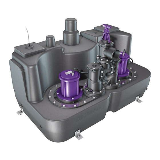
ALLGEMEINES 2.4.1 Baugruppen und Funktionsmerkmale Typenschild Abwasserbehälter Abwasserpumpe(n) Hosenrohr / Druckanschluss Rück ussverhinderer Absperrschieber * Zulaufanschluss DN100/150 Entlüftungsanschluss DN70 Reinigungsdeckel Anbohr ächen Zulauf Anschluss Handmembranpumpe DN40 Niveaugeber ** Klappe Rück ussverhinderer * Optional ** Tauchrohr (wenn nicht anders kon guriert) Die Abbildung kann sich in Form und Ausprägung 17 * von den Ausstattungsmerkmalen Ihrer Anlage unterscheiden. -
Page 9: Sicherheit
SICHERHEIT Sicherheit 3.1. Bestimmungsgemäße Verwendung Die Anlage ist ausschließlich für das Abpumpen von fäkalienfreiem und fäkalienhaltigem Abwasser zu verwenden. Ein Einsatz der Anlage in explosionsgefährdeter Umgebung ist unzulässig. Alle nicht durch eine ausdrückliche und schriftliche Freigabe des Herstellers erfolgten • Um- oder Anbauten •... -
Page 10: Gefahr Durch Heiße Ober Ächen
SICHERHEIT 3.4.2 Während dem Betrieb erhitzen sich Antriebsmotore von Pumpen. Ein Berühren der heißen Ober ächen kann zu Verbrennungen führen. Abkühlung vor dem Berühren sicherstellen. 3.4.3 Gefahr durch Lärm Der Betrieb der Anlage kann einen hohen Lärmpegel verursachen*. Tragen Sie bei Bedarf entsprechende Schutz- ausrüstung und sorgen sie für schalldämmende Maßnahmen. -
Page 11: Montage
MONTAGE Montage 4.1. Montagevoraussetzungen • Die Anlage muss auf ausreichend tragfähigen (Gewicht in befülltem Zustand berücksichtigen) und ebenen Un- tergrund aufgestellt werden. • Der Untergrund muss zur Aufnahme der Bodenbefestigungen (pro Schraube, 0,9 kN) geeignet sein, die ein Auf- schwimmen der Anlage verhindern sollen. •... -
Page 12: Zulauf Anschließen
MONTAGE 4.2.1 Zulauf anschließen • Zulau eitung am Stutzen <19> anschließen. Der Zulauf kann optional an einer der Anbohr ächen (siehe 2.5) montiert werden. Dabei sicherstellen: • Zulauf oberhalb des Niveaufühlers für das Einschalten der Pumpe(n) anordnen. Sonst kommt es zum Rückstau in den Zulauf. Alternativ müssen die Schaltpunkte angepasst werden. -
Page 13: Druckleitung Anschließen
MONTAGE 4.2.3 Druckleitung anschließen Je nach Anlagenausführung kommen Armaturen aus Kunststoff oder Grauguss zum Einsatz. Armatur aus Kunststoff • Ggf. Absperrschieber <17> montieren (Option). • Druckleitung <A> wie folgt anschließen: • senkrecht am Ablaufanschluss <20>. • waagerecht am Absperrschieber. Anzugsmomente beachten, siehe Seite 6.4. Armatur aus Grauguss •... -
Page 14: Bodenbefestigung
Einstellung im Menü 3.6 Leistungsgröße SPF 1500 Sonderpumpe <4A SPF 3000 Sonderpumpe <6,3A SPF 4500 oder SPF 5500 Sonderpumpe <10,0A Anschließend die Parameter der nachstehenden Tabelle einstellen bzw. die Einstellung überprüfen. Zwei Punkte bei KESSEL Hebeanlage Aqualift F XL 200 14/168 2016/05... - Page 15 SDS [d] 0…14 A = Einstellen, prüfen B = Optional C = Nur durch von KESSEL geschultes Personal verändern. Tauchrohr (Unterkante Tauchrohr -> Unterkante Behälter) Zeit die vergeht, bist die 2te Pumpe anläuft (Duo) Sowie die Zeit die vergeht, bis eine Pumpe erneut starten kann.
-
Page 16: Inbetriebnahme Durchführen
INBETRIEBNAHME DURCHFÜHREN Inbetriebnahme durchführen Ein Trockenlauf der Abwasserpumpe(n) ist unbedingt zu vermeiden, sie könnten beschädigt werden. Niemals Pumpen einschalten, wenn der Abwasserbehälter nicht mindestens bis zum Pegelstand Minimum befüllt ist. 5.1. Funktionskontrolle / Inbetriebnahme durchführen. 5.1.1 Schaltstellung EIN Erfolgt der Zulauf anstelle über den Zulaufanschluss durch eine der Anbohr ächen, Pegelstand für Schaltstellung EIN kontrollieren und ggf. -
Page 17: Technische Daten
TECHNISCHE DATEN Technische Daten 6.1. Allgemein Gewicht der Anlagen (leer), je nach Ausführung 70 bis 250 kg. 6.2. Pumpen Pumpe SPF... 1400 1500 3000 4500 5500 Gewicht [kg] Leistung P1 1,6 kW 1,4 kW 3,2 kW 4,5 kW 5,7 kW Leistung P2 1,1 kW 1,1 kW... -
Page 18: Anzugsmomente Schraubverbindungen
TECHNISCHE DATEN 6.4. Anzugsmomente Schraubverbindungen Pumpe an Pumpen ansch 7 Nm Niveaufühler und Revisionsdeckel 5 Nm Rück ussverhinderer (Kunststoff) 7 Nm 6.5. Nutzvolumina Abhängigkeit des Nutzvolumens in ca. Liter zur Einlaufposition. [15] Nutzvolumen ca. Liter bei Einlaufposition [mm] Behältervolumen 170[mm] 265[mm] 365[mm] Stutzen... -
Page 19: Abmessungen
TECHNISCHE DATEN 6.6. Abmessungen Behältervolumen Breite <B> Länge <L> Höhe <H> [mm] [mm] [mm] Anlagenhöhe / Anschluss Druckleitung 200 Liter 1109 770 / 620 807 / 610 1027 / 978 300 Liter 1260 770 / 620 806 / 609 1042 / 994 450 Liter 1260 1089... -
Page 20: Wartung
WARTUNG Wartung 7.1. Sicherheitshinweise für die Wartung - Vor dem Öffnen des Abwasserbehälters für ausreichende Belüftung des Raumes sorgen. Zündquellen fern hal- ten und nicht rauchen. - Sicherstellen, dass die Pumpe(n) Umgebungstemperatur angenommen haben. - Zu- und Ablau eitungen müssen vor einer Arbeitsaufnahme entleert und drucklos sein. - Pegelstand im Abwasserbehälter muss sich unterhalb der Befestigungsebene (Pumpen ansch) der Abwasser- pumpen be nden (Abb. - Page 21 WARTUNG 7.3.3 Anlage für Wartung vorbereiten, entleeren • Zulauf verschließen bzw. sicherstellen, dass kein Abwasser zu ießen kann. • Anlage leerpumpen, dazu entweder - Wasser einfüllen, bis Pumpe 1 anläuft. Wasserzufuhr abstellen, die Pumpe läuft, bis Pegelstand „Minimum“ erreicht ist. oder Achtung: Gefahr von Materialschäden! Pumpe darf nicht trockenlaufen.
-
Page 22: Rück Ussverhinderer Überprüfen
WARTUNG • Revisionsdeckel abschrauben. • Tauchrohr abmontieren. • Sicherstellen, dass sich der Pegelstand <A> im Abwasserbehälter unterhalb des Pumpen ansches <33> be ndet. Ggf. Abwasserbehälter leerpumpen. Anschluss Handpumpe siehe 2.5. 7.3.4 [21] • Anlage für Wartung vorbereiten, entleeren, siehe 7.3.3 Armatur aus Kunststoff •... -
Page 23: Gehäuse Abwasserpumpe(N) Reinigen
WARTUNG 7.3.5 Gehäuse Abwasserpumpe(n) reinigen • Anlage für Wartung vorbereiten, entleeren, siehe 7.3.3 Beide Abwasserpumpen reinigen, dazu: • Alle Befestigungsschrauben herausschrauben Alle Pumpen sind mit zwei Abdrückmöglichkeiten am Befestigungs ansch ausgerüstet. • Pumpe <14> herausheben und reinigen. • Sicherstellen, dass die Pumpe frei von Beschädigungen ist. •... -
Page 24: Ersatzteile
ERSATZTEILE Ersatzteile 8.1. [25] Pos. Bezeichnung Art.Nr. Pos. Bezeichnung Art.Nr. 230 V Mono Comfort 28731 Flanschdichtung für SPF 1400-4500 206-175 230 V Duo Comfort 28746 Schrauben (14 St.) 206-090 400 V Mono für SPF 1500 28755 Pumpen ansch für SPF 1400-3000 206-161 400 V Mono für SPF 3000 28756... -
Page 25: Armaturen Aus Grauguss
ERSATZTEILE 8.2. Armaturen aus Grauguss [26] Pos. Bezeichnung Art.Nr. Pos. Bezeichnung Art.Nr. Schaltgerät 28731 Schrauben (14 St.) 206-090 230 V Mono Comfort 28746 Pumpen ansch 230 V Duo Comfort 28755 für SPF 1400-4500 206-161 400 V Mono für SPF 1500 28756 für SPF 5500 auf Anfrage... -
Page 26: Dop
26/168 2016/05... - Page 27 27/168 2016/05...
- Page 28 Führend in Entwässerung Privater Wohnungsbau ohne Kanalanbindung 1 2 3 4 1 2 3 4 Öffentlicher Bau z.B. Krankenhaus Öffentlicher Bau z.B. Freizeitanlagen 1 2 3 4 Gewerblicher Bau z.B. Hotel Gewerblicher Bau z.B. Industriebau 2 3 5 Gewerblicher Bau z.B.
- Page 29 INSTALLATION AND OPERATING MANUAL KESSEL - Aqualift F XL Mono/Duo Lifting Stations for wastewater with or without sewage for above ground installation in frost free areas Polymer gate valve Cast iron gate valve Product Advantages SDS Control Unit (Self Diagnosis System)
-
Page 30: Table Of Contents
30/168 2016/05... - Page 31 Table of contents General Introduction and welcome Product description, general 2.2.1 Versions 2.2.2 Type plate General information about this operating and maintenance manual Delivery scope Assemblies and functional elements Safety Proper use Staff selection and quali cation Organisational safety measures Risks arising from the product 3.4.1 Risk due to electrical current and cables 3.4.2 Danger through hot surfaces...
- Page 32 Maintenance Safety instructions for maintenance Maintenance activities, intervals Maintenance activities 7.3.1 Visual check 7.3.2 Checking the shut-off valve 7.3.3 Preparing the station for maintenance, draining 7.3.4 Checking the back ow protection device 7.3.5 Cleaning the wastewater pump(s) housing 7.3.6 Cleaning the wastewater container and level detector 7.3.7 Performing a function check Troubleshooting Spare parts...
-
Page 33: General
The wastewater container incorporates the pump(s) and the level sensor(s). The assemblies are designed so that they can be easily attached to a KESSEL control unit. The station is supplied in three different versions (volume capacities) and with different pumps. Depending on requirements, ttings and shut-off valves made of plastic or grey cast iron can also be supplied 1.2.1... -
Page 34: Type Plate
10 Revision status of the hardware 28 CE mark Hebenanlage Aqualift F XL Mono/Duo XXXXX www.kessel.de/info XXXXXXXXXX Hebeanlage Aqualift F XL Mono/Duo XXXXX XXXV XXHz X,XA X,XkW XXm/h S3 XX% ED IP XX (XmWS/2h) Ser. Nr. XXXXXXXXX RevStd.: X.X MM/JJ... -
Page 35: General Information About This Operating And Maintenance Manual
GENERAL 1.3. General information about this operating and maintenance manual Used symbols and legends <1> Reference in the text to a legend number in an illustrationw Reference to an illustration • Work step List Italics Text in italics: reference to a paragraph/item in the control menu CAUTION: Warns about a risk to persons and material. - Page 36 GENERAL Type plate Wastewater container Wastewater pump(s) Y-branch pipe / pressure connection Back ow protection device Shut-off valve Intake connection DN100/150 Venting connection DN70 Cleaning cover Intake scored areas Manual diaphragm pump connection DN40 Level detector ** Back ow protection device ap * Optional ** Immersion pipe (if not con gured otherwise) Your Station may differ from the image with regard...
-
Page 37: Safety
SAFETY Safety 2.1. Proper use The Station is to be used only for the extraction of wastewater, including that which contains sewage. Any use of the Station in an environment at risk from explosions is not permissible. Any of the following actions that are not approved explicitly and in writing by the manufacturer •... -
Page 38: Danger Through Hot Surfaces
SAFETY 2.4.2 Danger through hot surfaces The drive motors of the pumps become hot during operation. Contact with the hot surfaces may lead to severe burns and damage to objects. Wear suitable personal protective equipment and ensure suf cient cooling before contact. -
Page 39: Assembly
ASSEMBLY Assembly 3.1. Conditions for assembly • The Station must be set on a suf ciently load-bearing (determined according to lled weight) and level surface. • The surface must be suitable for bearing the fastenings (0.9 kN per bolt), in order to prevent the station from oating. -
Page 40: Connecting The Inlet
ASSEMBLY 3.2.1 Connecting the inlet • Connect the intake pipe to nozzle <19>. The intake can also be assembled on one of the scored areas (see 2.5). When doing this: • Arrange the intake above the level sensor for switching on the pump(s). -
Page 41: Connecting The Pressure Pipe
ASSEMBLY 3.2.3 Connecting the pressure pipe Depending on the station arrangement, plastic or grey cast iron ttings are used Plastic tting • Mount shut-off valve <17> if required (optional). • Connect pressure pipe <A> as follows: • vertically on the drainage connection <20>. •... -
Page 42: Fastening To The Ground
Cust. pump <4A SPF 3000 Cust. pump <6.3A SPF 4500 or SPF 5500 Cust. pump <10.0A Following this, set the parameters in the following table and/or check the settings. Two points for KESSEL Aqualift F XL 200 lifting station 42/168 2016/05... - Page 43 Auto SDS [d] 0…14 A = Set, check B = Optional C = Changes to be carried out only by trained KESSEL personnel.. Immersion pipe (bottom immersion pipe -> bottom container) Time that elapses before the second pump starts (Duo) as well as the time that elapses before a pump can restart.
-
Page 44: Conducting Start-Up
CONDUCTING START-UP Conducting start-up Prevent the wastewater pump(s) from running dry as this may cause them to be damaged. Never switch on pumps if the wastewater container is not lled to the minimum level. 4.1. Conducting function check / start-up 4.1.1 Switch position ON If the intake occurs via one of the scored areas instead of the intake connection, check the level for the switch... -
Page 45: Technical Data
TECHNICAL DATA Technical data 5.1. General Weight of station (empty), 70 to 250 kg depending on version.. 5.2. Pumps Pump SPF... 1400 1500 3000 4500 5500 Weight [kg] Power P1 1,6 kW 1,4 kW 3,2 kW 4,5 kW 5,7 kW Power P2 1,1 kW 1,1 kW... -
Page 46: Bolt Connections Tightening Torques
TECHNICAL DATA 5.4. Bolt connections tightening torques Pump on pump ange 7 Nm Level sensor and maintenance port 5 Nm Back ow protection device (plastic) 7 Nm 5.5. Dependence of the effective volume on intake position in approx. litres. [15] Effective volume in approx. -
Page 47: Measurements
TECHNICAL DATA 5.6. Measurements Container capacity Width <B> Length <L> Height <H> [mm] [mm] [mm] Station height / pressure pipe 200 litres 1109 770 / 620 807 / 610 1027 / 978 300 litres 1260 770 / 620 806 / 609 1042 / 994 450 litres 1260... -
Page 48: Maintenance
MAINTENANCE Maintenance 6.1. Safety instructions for maintenance - Ensure that the room is well ventilated before opening the wastewater container. Keep sources of ignition away and do not smoke. - Ensure that the pump(s) have reached ambient temperature - Intake and outlet pipes must be emptied and free of pressure before beginning work. - The level in the wastewater container must be below the fastening level (pump ange) of the wastewater pumps (Fig. -
Page 49: Preparing The Station For Maintenance, Draining
MAINTENANCE 6.3.3 Preparing the station for maintenance, draining • Close the intake and ensure that no wastewater can ow in • Pump the station empty, for this either - ll with water until pump 1 starts. Turn off the water intake, the pump will run until the level „minimum“ is reached Attention: Danger of material damages! Pump must not run dry - Use the control unit (manual control) to control the pump until the wastewater container is empty. -
Page 50: Checking The Back Ow Protection Device
MAINTENANCE • Unscrew the maintenance port. • Remove the immersion pipe. • Ensure that the level <A> in the wastewater container is beneath the pump ange <33>. Pump the wastewater container empty if required. See 2.5 for hand pump connection. [21] 6.3.4 •... -
Page 51: Cleaning The Wastewater Pump(S) Housing
MAINTENANCE 6.3.5 Cleaning the wastewater pump(s) housing • Preparing the station for maintenance, draining, see 7.3.3 Clean both wastewater pumps, here: • Unscrew all fastening bolts All pumps are equipped with two fastenings on the fastening ange • Lift out and clean the pump <14>. •... -
Page 52: Spare Parts
SPARE PARTS Spare parts 7.1. [25] Pos. Designation Item no. Pos. Designation Item no. 230 V Mono Comfort 28731 Flange seal for SPF 1400-4500 206-175 230 V Duo Comfort 28746 Bolts (x 14) 206-090 400 V Mono for SPF 1500 28755 Pump ange for SPF 1400-3000 206-161... -
Page 53: Grey Cast Iron Ttings
SPARE PARTS 7.2. [26] Pos. Designation Item no. Pos. Designation Item no. Control unit 28731 Bolts (x 14) 206-090 230 V Mono Comfort 28746 Pump ange 230 V Duo Comfort 28755 for SPF 1400-4500 206-161 400 V Mono for SPF 1500 28756 for SPF 5500 Upon request... -
Page 54: Dop
54/168 2016/05... - Page 55 55/168 2016/05...
- Page 56 Leading in Drainage Private homes without public sewage connection 1 2 3 4 1 2 3 4 Public buildings (e.g. hospital) Public buildings (e.g. leisure facility) 1 2 3 4 Commercial buildings (e.g. hotel) Commercial buildings (e.g. industrial / manu- facturing facilities) 2 3 5 Commercial buildings...
- Page 57 INSTRUCTIONS DE MONTAGE, D‘UTILISATION ET DE MAINTENANCE Poste de relevage KESSEL Aqualift F XL Mono/Duo pour eaux-vannes et eaux grises pour la pose libre dans des locaux à l’abri du gel Avantages du produit Robinetteries en plastique Robinetteries en fonte Sécurité...
- Page 58 58/168 2016/05...
-
Page 59: Sommaire
SOMMAIRE Sommaire Sommaire En général Introduction et accueil Description générale du produit 2.2.1 Versions 2.2.2 Plaque signalétique Informations d‘ordre général concernant ces instructions d‘utilisation et de maintenance Fournitures Sous-groupes et éléments fonctionnels Sécurité Utilisation conforme à l‘usage prévu Sélection et quali cation du personnel Consignes de sécurité... - Page 60 SOMMAIRE Maintenance Consignes de sécurité spéci ques à la maintenance Interventions de maintenance, intervalle Interventions de maintenance 7.3.1 Contrôle visuel 7.3.2 Véri cation de la vanne d‘arrêt 7.3.3 Préparation du poste à la maintenance, vidage 7.3.4 Véri cation du dispositif antire ux 7.3.5 Nettoyage des carters de la/des pompe(s) d‘assainissement 7.3.6 Nettoyage du bac collecteur des eaux usées et du capteur de niveau 7.3.7 Contrôle du fonctionnement...
-
Page 61: En Général
Introduction et accueil Chère cliente, Cher client, Nous vous félicitons de votre achat d‘un produit KESSEL. Ce produit sera certainement en mesure de répondre à toutes vos attentes. Nous vous souhaitons un fonctionnement sans faille et réussi. Ce document décrit le montage et la maintenance du poste de relevage KESSEL Aqualift F XL utilisé ensemble avec un gestionnaire. -
Page 62: Plaque Signalétique
10 Version de mise à jour du matériel informatique 28 Label CE Hebenanlage Aqualift F XL Mono/Duo XXXXX www.kessel.de/info XXXXXXXXXX Hebeanlage Aqualift F XL Mono/Duo XXXXX XXXV XXHz X,XA X,XkW XXm/h S3 XX% ED IP XX (XmWS/2h) Ser. Nr. XXXXXXXXX RevStd.: X.X... -
Page 63: Informations D'ordre Général Concernant Ces Instructions D'utilisation Et De Maintenance
EN GÉNÉRAL 2.3. Informations d‘ordre général concernant ces instructions d‘utilisation et de maintenance Pictogrammes et légendes utilisés <1> Information dans le texte attirant l‘attention sur un numéro de légende dans une gure Renvoi à une gure • Étape opératoire Énumération Italique caractères en italique : renvoi à... -
Page 64: Sous-Groupes Et Éléments Fonctionnels
EN GÉNÉRAL Sous-groupes et éléments fonctionnels Plaque signalétique Bac collecteur des eaux usées Pompe(s) d‘assainissement Tuyau en Y / raccord de la tubulure de refou- lement Dispositif antire ux Vanne d‘arrêt * Raccord de la tubulure d‘entrée DN100/150 Raccord de purge d‘air DN70 Couvercle de visite Surfaces de perçage d‘entrée Raccord de la pompe à... -
Page 65: Sécurité
SÉCURITÉ Sécurité 3.1. Utilisation conforme à l‘usage prévu Le poste sert exclusivement au refoulement des eaux usées et des eaux-vannes. L‘utilisation du poste dans des zones à risque d‘explosion est interdit. Il faut savoir, à défaut d‘une autorisation expresse et écrite du fabricant, que toutes les •... -
Page 66: Danger Lié Aux Surfaces Chaudes
SÉCURITÉ 3.4.2 Danger lié aux surfaces chaudes Les moteurs d‘entraînement des pompes chauffent considérablement en fonctionnement. Un contact avec des surfaces chaudes ou brûlantes risque de provoquer des brûlures et des dégâts matériels graves. Porter un équipement de protection personnelle appropriée et patienter jusqu‘au refroidissement avant tout contact. -
Page 67: Montage
MONTAGE Montage 4.1. Conditions préalables au montage • La mise en place du poste doit se faire sur un support d‘une stabilité suf sante (observer le poids en l‘état rem- ) et plan. • Le support doit être approprié au logement des plaques de xation (0,9 kN par vis) destinées à prévenir le ot- tement du poste. -
Page 68: Raccordement De L'entrée
MONTAGE 4.2.1 Raccordement de l‘entrée • Raccorder la conduite d‘entrée au manchon <19>. Le montage de l‘entrée est possible en option à l‘une des surfaces de perçage (voir le point 2.5). Veiller à ce qui suit dans ce contexte : •... -
Page 69: Raccordement De La Conduite De Refoulement
MONTAGE 4.2.3 Raccordement de la conduite de refoulement Les robinetteries montées sont composées de plastique ou de fonte grise selon la version du poste Robinetterie en plastique • Au besoin, monter la vanne d‘arrêt <17> (en option). • Raccorder la conduite de refoulement <A> comme suit : •... -
Page 70: Fixation Au Sol
SPF 3000 Pompe spéciale <6,3A SPF 4500 ou SPF 5500 Pompe spéciale <10,0A Con gurer ensuite les paramètres du tableau ci-après ou véri er les con gurations. Deux pompes si poste de relevage KESSEL Aqualift F XL 200 70/168 2016/05... - Page 71 SDS [d] 0...14 A = régler, véri er B = option C = modi cation réservée au domaine de compétence du personnel quali é de KESSEL. Tube plongeur (tube plongeur fond -> récipient inférieur) Temps qui s‘écoule jusqu‘au démarrage de la 2ème pompe (Duo) et temps qui s‘écoule jusqu‘à ce qu‘une pompe redémarre.
-
Page 72: Mise En Service
MISE EN SERVICE Mise en service Exclure tout fonctionnement à sec de la/des pompe(s) d‘assainissement qui risquerait de les détériorer. Ne ja- mais mettre les pompes en marche tant que le bac collecteur des eaux usées n‘est pas rempli jusqu‘au niveau minimum. -
Page 73: Caractéristiques Techniques En Général
CARACTÉRISTIQUES TECHNIQUES Caractéristiques techniques 6.1. En général Poids des postes (vides) de 70 à 250 kg selon la version. 6.2. Pompes Pompe SPF... 1400 1500 3000 4500 5500 Poids (kg) Puissance P1 1,6 kW 1,4 kW 3,2 kW 4,5 kW 5,7 kW Puissance P2 1,1 kW... -
Page 74: Couples De Serrage Des Raccords À Vis
CARACTÉRISTIQUES TECHNIQUES 6.4. Couples de serrage des raccords à vis Pompe à la bride de pompe 7 Nm Capteur de niveau et couvercle de contrôle 5 Nm Dispositif antire ux (plastique) 7 Nm 6.5. Volume utile Dépendance du volume utile approximatif en litres par rapport à l‘entrée. [15] Volume utile approximatif litres par rapport à... -
Page 75: Dimensions
CARACTÉRISTIQUES TECHNIQUES 6.6. Dimensions Volume du bac Largeur <B> Longueur <L> Hauteur <H> [mm] collecteur [mm] [mm] Hauteur du poste / raccord de la conduite de refoulement 200 litres 1109 770 / 620 807 / 610 1027 / 978 300 litres 1260 770 / 620 806 / 609... -
Page 76: Maintenance
MAINTENANCE Maintenance 7.1. - Veiller à une ventilation suf sante de la pièce avant d‘ouvrir le bac collecteur des eaux usées. Éloigner toutes les source d’allumage et ne pas fumer. - S‘assurer que la/les pompe(s) est/sont à température ambiante. - Vider et dépressuriser les conduites d‘entrée et de sortie avant d‘entamer les travaux. - Le niveau dans le bac collecteur des eaux usées doit se situer au-dessous du niveau de xation (de la bride de pompe) des pompes d‘assainissement (Fig. -
Page 77: Préparation Du Poste À La Maintenance, Vidage
MAINTENANCE 7.3.3 Préparation du poste à la maintenance, vidage • Fermer l‘entrée ou s‘assurer que les eaux usées ne peuvent plus couler dans le bac. • Vider le poste par pompage, pour ce faire - ajouter de l‘eau jusqu‘à ce que la pompe 1 démarre. Débrancher l‘apport d‘eau et la pompe fonctionne jusqu‘à l‘atteinte du niveau «... -
Page 78: Véri Cation Du Dispositif Antire Ux
MAINTENANCE • Dévisser le couvercle de contrôle. • Démonter le tube plongeur. • S‘assurer que le niveau <A> dans le bac collecteur des eaux usées soit au-dessous de la bride de pompe <33>. Au besoin, vider le bac collecteur des eaux usées par pompage. Voir le point 2.5 pour le raccordement de la pompe manuelle. -
Page 79: Nettoyage Des Carters De La/Des Pompe(S) D'assainissement
MAINTENANCE 7.3.5 Nettoyage des carters de la/des pompe(s) d‘assainissement • Préparation du poste à la maintenance, vidage, voir le point 7.3.3 Nettoyer les deux pompes d‘assainissement, pour ce faire : • Dévisser toutes les vis de xation Toutes les pompes sont équipées de deux possibilités de chasse sur la bride de xation. -
Page 80: Pièces De Rechange
PIÈCES DE RECHANGE Pièces de rechange 8.1. Robinetteries en plastique [25] Point Désignation Réf. n° Point Désignation Réf. n° 230 V Mono Confort 28731 Joint bride pour SPF 1400-4500 206-175 230 V Duo Confort 28746 Vis (14 pièces) 206-090 400 V Mono pour SPF 1500 28755 Bride de pompe pour SPF 1400-3000 206-161... -
Page 81: Robinetteries En Fonte Grise
PIÈCES DE RECHANGE 8.2. Robinetteries en fonte grise [26] Point Désignation Réf. n° Point Désignation Réf. n° Gestionnaire 28731 Vis (14 pièces) 206-090 230 V Mono Confort 28746 Bride de la pompe 230 V Duo Confort 28755 pour SPF 1400-4500 206-161 400 V Mono pour SPF 1500 28756... -
Page 82: Dop
82/168 2016/05... - Page 83 83/168 2016/05...
- Page 84 Leader en solution d’assainissement Construction de logements privés sans raccordement au réseau d’assainissement public 1 2 3 4 1 2 3 4 Construction de logements Construction publique, par privés sans raccordement au exemple aménagement de loisirs réseau d’assainissement public 1 2 3 4 Construction industrielle 2 3 5...
- Page 85 ISTRUZIONI PER L‘INSTALLAZIONE, L‘USO E LA MANUTENZIONE Impianto di sollevamento KESSEL Aqualift F XL Mono/Duo per le acque di scarico contenenti e non contenenti sostanze fecali per l’installazione libera in locali privi di gelo Vantaggi del prodotto Valvole in plastica...
- Page 86 86/168 2016/05...
-
Page 87: Indice
INDICE Indice Indice In generale Introduzione e saluto Descrizione del prodotto, in generale 2.2.1 Esecuzioni 2.2.2 Targhetta Indicazioni generali sulle presenti istruzioni per l’uso e la manutenzione Fornitura Gruppi costruttivi ed elementi funzionali Sicurezza Uso conforme alla destinazione Scelta e quali ca del personale Misure di sicurezza organizzative Pericoli derivanti dal prodotto 3.4.1 Pericoli causati dalla corrente elettrica e dai cavi... - Page 88 INDICE Manutenzione Avvertenze di sicurezza per la manutenzione Mansioni di manutenzione, intervalli Mansioni di manutenzione 7.3.1 Controlli visuali 7.3.2 Controllo della valvola a saracinesca 7.3.3 Preparazione dell‘impianto per la manutenzione, svuotamento 7.3.4 Controllo del dispositivo anti-ri usso 7.3.5 Pulizia dell‘alloggiamento delle pompe delle acque di scarico 7.3.6 Pulizia del contenitore delle acque di scarico e del sensore di livello 7.3.7 Esecuzione dei controlli funzionali Ricerca di errori...
-
Page 89: In Generale
(o le pompe) ed il sensore di livello (o i sensori di livello). I gruppi costruttivi sono concepiti in modo da poter essere collegati direttamente ad una centralina KESSEL. L‘impianto è fornito in tre diverse ese- cuzioni (volumi di raccolta) e con diverse pompe. -
Page 90: Targhetta
7 Codice QR 10 Stato di revisione dell‘hardware 28 Marcatura CE Hebenanlage Aqualift F XL Mono/Duo XXXXX www.kessel.de/info XXXXXXXXXX Hebeanlage Aqualift F XL Mono/Duo XXXXX XXXV XXHz X,XA X,XkW XXm/h S3 XX% ED IP XX (XmWS/2h) Ser. Nr. XXXXXXXXX RevStd.: X.X MM/JJ... -
Page 91: Indicazioni Generali Sulle Presenti Istruzioni Per L'uso E La Manutenzione
IN GENERALE 2.3. Indicazioni generali sulle presenti istruzioni per l’uso e la manutenzione Simboli utilizzati e legenda <1> Riferimento nel testo ad un numero di legenda in un‘immagine Riferimento ad una gura • Passo di lavoro Numerazione Corsivo Scritta in corsivo: riferimento ad una sezione / un punto nel menu di comando PRUDENZA: avverte circa un pericolo per le persone ed il materiale. -
Page 92: Gruppi Costruttivi Ed Elementi Funzionali
IN GENERALE 2.5. Gruppi costruttivi ed elementi funzionali Targhetta Contenitore delle acque di scarico Pompa/e delle acque di scarico Tubo a Y / Raccordo di mandata Dispositivo anti-ri usso Valvola a saracinesca * Collegamento d‘entrata DN100/150 Collegamento di s ato DN70 Coperchio di pulizia Super ci perforabili d‘entrata Collegamento della pompa a membrana ma-... -
Page 93: Sicurezza
SICUREZZA Sicurezza 3.1. Uso conforme alla destinazione L‘impianto è destinato esclusivamente al pompaggio di svuotamento delle acque di scarico contenenti e non contenenti sostanze fecali. Un impiego dell‘impianto negli ambienti a rischio di esplosione non è ammesso. In assenza di un‘autorizzazione espressa ed in forma scritta da parte del produttore, •... -
Page 94: Pericoli Causati Dalle Super Ci Calde
SICUREZZA 3.4.2 Durante il funzionamento, i motori di comando delle pompe possono surriscaldarsi. Il contatto con le super ci calde può causare gravi ustioni e danni materiali. Indossare dei dispositivi di protezione adeguati ed assicurare un raffreddamento suf ciente prima del contatto. 3.4.3 Pericoli causati dal rumore Il funzionamento dell‘impianto può... -
Page 95: Montaggio
MONTAGGIO Montaggio 4.1. Requisiti di montaggio • L‘impianto deve essere montato su un sottofondo suf cientemente portante (tenere conto del peso in condizioni piene ) e piano. • Il sottofondo deve essere adatto all‘accoglimento dei ssaggi al pavimento (0,9 kN per vite), che dovrebbero evitare il galleggiamento dell‘impianto. -
Page 96: Collegamento Dell'entrata
MONTAGGIO 4.2.1 Collegamento dell‘entrata • Collegare il condotto di alimentazione al bocchettone <19>. L‘entrata può essere montata alternativamente ad una super cie perforabile (vedere 2.5). In quel caso, prestare attenzione a quanto segue: • Collocare l‘entrata al di sopra del sensore di livello per l‘accensione delle pompe. -
Page 97: Collegamento Del Condotto Di Mandata
MONTAGGIO 4.2.3 Collegamento del condotto di mandata A seconda dell‘esecuzione dell‘impianto, le valvole impiegate sono in plastica o in ghisa Valvole in plastica • Eventualmente montare una valvola a saracinesca <17> (opzione). • Collegare il condotto di mandata <A> come segue: •... -
Page 98: Fissaggio Al Pavimento
SPF 3000 Pompa speciale < 6,3 A SPF 4500 o SPF 5500 Pompa speciale < 10,0 A In ne, impostare i parametri della tabella seguente ovvero controllare l‘impostazione. Due punti con impianto di sollevamento KESSEL Aqualift F XL 200 98/168 2016/05... - Page 99 SDS automatico [d] 0…14 A = impostazione, controllo B = opzionale C = modi cabile solo dal personale addestrato KESSEL. Pescante (dip pescante -> contenitore basso) Tempo che trascorre prima che la 2a pompa si avvii (Duo), al pari del tempo che trascorre prima che una pompa possa avviarsi nuovamente.
-
Page 100: Esecuzione Della Messa In Funzione
ESECUZIONE DELLA MESSA IN FUNZIONE Esecuzione della messa in funzione Il funzionamento a secco delle pompe delle acque di scarico deve essere assolutamente evitato, in quanto pot- rebbero danneggiarsi. Non accendere mai le pompe se il contenitore delle acque di scarico non è pieno almeno no al livello dell‘acqua minino. -
Page 101: Dati Tecnici In Generale
DATI TECNICI Dati tecnici 6.1. In generale Peso dell‘impianto (vuoto), da 70 a 250 kg a seconda dell‘esecuzione. 6.2. Pompe Pompa SPF... 1400 1500 3000 4500 5500 Peso [kg] Potenza P1 1,6 kW 1,4 kW 3,2 kW 4,5 kW 5,7 kW Potenza P2 1,1 kW 1,1 kW... -
Page 102: Momenti Di Serraggio Dei Collegamenti A Vite
DATI TECNICI 6.4. Momenti di serraggio dei collegamenti a vite Pompa sulla angia della pompa 7 N m Sensore di livello e coperchio di revisione 5 N m Dispositivo anti-ri usso (plastica) 7 N m 6.5. Volumi utili Dipendenza dei volumi utili in litri approssimativi dalla posizione di ingresso. [15] Volume utile, litri approssimativi in base alla posizione di ingresso [mm]... -
Page 103: Misure
DATI TECNICI 6.6. Misure Volume del cont- Larghezza Lunghezza <L> Altezza <H> [mm] enitore <B> [mm] Altezza dell‘impianto / collegamento del condotto [mm] di mandata 200 litri 1109 770 / 620 807 / 610 1027 / 978 300 litri 1260 770 / 620 806 / 609 1042 / 994... -
Page 104: Manutenzione
MANUTENZIONE Manutenzione 7.1. Avvertenze di sicurezza per la manutenzione - Prima dell‘apertura del contenitore delle acque di scarico, garantire un‘aerazione suf ciente. Tenere lontane le fonti di ignizione e non fumare. - Accertare che le pompe abbiano raggiunto la temperatura ambiente. - I condotti di alimentazione e di scarico devono essere svuotati e privati della pressione prima dell‘inizio dei lavori. -
Page 105: Preparazione Dell'impianto Per La Manutenzione, Svuotamento
MANUTENZIONE 7.3.3 Preparazione dell‘impianto per la manutenzione, svuotamento • Chiudere l‘entrata ovvero accertare che non possano af uire acque di scarico. • Svuotare l‘impianto: a tale ne - Riempire con acqua no a fare avviare la pompa 1. Interrompere l‘alimentazione d‘acqua e lasciare funzionare la pompa no al raggiungimento del livello dell‘acqua „Minimo“. -
Page 106: Controllo Del Dispositivo Anti-Ri Usso
MANUTENZIONE • Svitare il coperchio di revisione. • Smontare il pescante. • Accertarsi che il livello dell‘acqua <A> nel contenitore delle acque di scarico si trovi al di sotto della angia della pompa <33>. Eventualmente svuotare con la pompa il contenitore delle acque di scarico. Collegamento della pompa manuale, vedere 2.5. -
Page 107: Pulizia Dell'alloggiamento Delle Pompe Delle Acque Di Scarico
MANUTENZIONE 7.3.5 Pulizia dell‘alloggiamento delle pompe delle acque di scarico • Preparazione dell‘impianto per la manutenzione, svuotamento, vedere 7.3.3 Pulire entrambe le pompe delle acque di scarico; a tale ne: • Svitare tutte le viti di ssaggio Tutte le pompe sono dotate di due possibilità di compressione sulla angia di ssaggio. -
Page 108: Pezzi Di Ricambio
PEZZI DI RICAMBIO Pezzi di ricambio 8.1. Valvole in plastica [25] Posi- Denominazione Codice arti- Posi- Denominazione Codice zione colo zione articolo 230 V Mono Comfort 28731 Guarnizione a angia per SPF 1400-4500 206-175 230 V Duo Comfort 28746 Viti (14 pezzi) 206-090 400 V Mono per SPF 1500 28755... -
Page 109: Valvole In Ghisa
PEZZI DI RICAMBIO 8.2. Valvole in ghisa [26] Posi- Denominazione Codice Posi- Denominazione Codice arti- zione articolo zione colo Centralina 28731 Viti (14 pezzi) 206-090 230 V Mono Comfort 28746 Flangia della pompa 230 V Duo Comfort 28755 per SPF 1400-4500 206-161 400 V Mono per SPF 1500 28756... -
Page 110: Dop
110/168 2016/05... - Page 111 111/168 2016/05...
- Page 112 Leader del drenaggio Edilizia residenziale privata senza collegamento alla fogna 1 2 3 4 1 2 3 4 Edilizia pubblica per es. Ospedale Edilizia pubblica per es. Impianti ricreativi 1 2 3 4 Edilizia commerciale per es. Albergo Edilizia commerciale per es.
- Page 113 GEBRUIKSAANWIJZING VOOR INBOUW, BEDIENING EN ONDERHOUD KESSEL-opvoerinstallatie Aqualift F XL Mono/Duo voor fecaliënhoudend en fecaliënvrij afvalwater voor vrije opstelling in vorstvrije ruimten Productvoordelen Kunststof armaturen Gegoten armaturen Veiligheid door schakelapparaat met ZDS-functie (zelfdiagnosesysteem) Druksensor voor veilige opname van vulpeil Aanboorvlakken voor...
- Page 114 114/168 2016/05...
-
Page 115: Inhoudsopgave Inhoudsopgave
INHOUDSOPGAVE Inhoudsopgave Inhoudsopgave Algemeen Inleiding en begroeting Productomschrijving, algemeen 2.2.1 Uitvoeringen 2.2.2 Typeplaatje Algemene instructies bij deze gebruiks- en onderhoudshandleiding Leveringsprogramma Modules en functie-elementen Veiligheid Voorgeschreven gebruik Personeelskeuze en -kwali catie Organisatorische veiligheidsmaatregelen Gevaren die uitgaan van het product 3.4.1 Gevaar door elektrische stroom en kabel 3.4.2 Gevaar door hete oppervlakken 3.4.3 Gevaar door lawaai 3.4.4 Gevaar voor de gezondheid... - Page 116 INHOUDSOPGAVE Onderhoud Veiligheidsinstructies voor het onderhoud Onderhoudsactiviteiten, intervallen Onderhoudsactiviteiten 7.3.1 Visuele controle 7.3.2 Afsluiters controleren 7.3.3 Installatie voor onderhoud voorbereiden, legen 7.3.4 Terugslagklep controleren 7.3.5 Behuizing afvalwaterpomp(en) reinigen 7.3.6 Afvalwatertank en niveausensor reinigen 7.3.7 Functiecontrole uitvoeren Opsporen van storingen Onderdelen Armaturen van kunststof Armaturen van grijs gietijzer 116/168...
-
Page 117: Algemeen
Wij zijn blij dat u gekozen hebt voor één van onze producten. Dit zal zeker in volle omvang voldoen aan uw eisen. Wij wensen u een vlot en succesvol gebruik toe. Dit document omschrijft de inbouw en het onderhoud van de KESSEL opvoerinstallatie Aqualift F XL, die samen met het besturingsapparaat wordt gebruikt. De gebruiks- en onderhoudshandleiding van het schakelapparaat maakt deel uit van de omschrijving van de installatie. -
Page 118: Typeplaatje
7 QR-code 10 Revisiestand van de hardware 28 CE-teken Hebenanlage Aqualift F XL Mono/Duo XXXXX www.kessel.de/info XXXXXXXXXX Hebeanlage Aqualift F XL Mono/Duo XXXXX XXXV XXHz X,XA X,XkW XXm/h S3 XX% ED IP XX (XmWS/2h) Ser. Nr. XXXXXXXXX RevStd.: X.X MM/JJ... -
Page 119: Algemene Instructies Bij Deze Gebruiks- En Onderhoudshandleiding
ALGEMEEN 2.3. Algemene instructies bij deze gebruiks- en onderhoudshandleiding Gebruikte symbolen en legenda <1> Verwijzing in de tekst naar een legendanummer op een afbeelding Referentie naar een afbeelding • Productiestap Opsomming Cursief Cursieve letterweergave: Referentie naar een paragraaf / punt in het besturingsmenu VOORZICHTIG: Waarschuwt tegen gevaar voor personen en materiaal. -
Page 120: Modules En Functie-Elementen
ALGEMEEN 2.5 Modules en functie-elementen Typeplaatje Afvalwatertank Afvalwaterpomp(en) Y-buis / drukaansluiting Terugslagklep Afsluiter * Toevoeraansluiting DN100/150 Ontluchtingsaansluiting DN70 Reinigingsdeksel Aanboorvlakken toevoer Aansluiting handmembraanpomp DN40 Niveausensor ** Klep terugslagklep * Optioneel ** Dompelpijp (tenzij anders gecon gureerd) De afbeelding kan in vorm en vormgeving 17 * verschillen van de uitvoeringskenmerken van uw installatie. -
Page 121: Veiligheid
VEILIGHEID Veiligheid 3.1. Voorgeschreven gebruik De installatie moet uitsluitend worden gebruikt voor het wegpompen van fecaliënvrij en fecaliënhoudend afvalwater. Het is niet toegestaan de installatie in een omgeving met explosiegevaar te gebruiken. Alle niet door een expliciete en schriftelijke vrijgave van de fabrikant uitgevoerde •... -
Page 122: Gevaar Door Hete Oppervlakken
VEILIGHEID 3.4.2 Gevaar door hete oppervlakken Tijdens het gebruik worden aandrijfmotoren van pompen warm. Aanraking van de hete oppervlakken kan tot erns- tige brandwonden en materiële schade leiden. Geschikte persoonlijke uitrusting dragen en vóór aanraking waarborgen dat er voldoende afkoeling is. 3.4.3 Gevaar door lawaai Het gebruik van de installatie kan een hoog geluidsniveau veroorzaken*. -
Page 123: Montage
MONTAGE Montage 4.1. Montagevoorwaarden • De installatie moet op voldoende stabiele (gewicht in gevulde staat in acht nemen) en egale ondergrond worden opgesteld. • De ondergrond moet geschikt zijn om de bodembevestigingen op te nemen (per schroef, 0,9 kN) die moeten voorkomen dat de installatie begint te drijven. -
Page 124: Toevoer Aansluiten
MONTAGE 4.2.1 Toevoer aansluiten • Toevoerleiding op de mof <19> aansluiten. De toevoer kan als optie op één van de aanboorvlakken (zie 2.5) gemonteerd worden. Hierbij waarborgen: • toevoer boven de niveausensor voor het inschakelen van de pomp(en) plaatsen. Anders ontstaat er opstuwing in de toevoer. Als alternatief moeten de schakelpunten worden aangepast. -
Page 125: Persleiding Aansluiten
MONTAGE 4.2.3 Persleiding aansluiten Afhankelijk van de uitvoering van de installatie worden armaturen van kunststof of grijs gietijzer gebruikt. Armatuur van kunststof • Evtl. Afsluiter <17> monteren (optie). • Persleiding <A> als volgt aansluiten: • verticaal aan de afvoeraansluiting <20>. •... -
Page 126: Bodembevesting
Speciale pomp <4 A SPF 3000 Speciale pomp <6,3 A SPF 4500 of SPF 5500 Speciale pomp <10,0 A Vervolgens de parameters van de onderstaande tabel instellen c.q. de instelling controleren. Twee punten bij KESSEL opvoerinstallatie Aqualift F XL 200 126/168 2016/05... - Page 127 ZDS [d] 0…14 A = instellen, controleren B = Optioneel C = Uitsluitend veranderen door personeel dat door KESSEL geschoold is. Dompelpijp (bottom Dompelpijp -> bottom container) Tijd die vergaat totdat de 2e pomp opstart (Duo) en de tijd die vergaat totdat een pomp opnieuw kan starten.
-
Page 128: Inbedrijfstelling Uitvoeren
INBEDRIJFSTELLING UITVOEREN Inbedrijfstelling uitvoeren Er moet absoluut worden voorkomen dat de afvalwaterpomp(en) drooglopen; zij kunnen dan beschadigd raken. Nooit pompen inschakelen, als de afvalwatertank niet minimaal tot en met niveaustand minimum gevuld is. 5.1. Functiecontrole / inbedrijfstelling uitvoeren. 5.1.1 Schakelstand AAN Als de toevoer door één van de aanboorvlakken verloopt i.p.v. -
Page 129: Technische Gegevens
TECHNISCHE GEGEVENS Technische gegevens 6.1. Algemeen Gewicht van de installaties (leeg), afhankelijk van uitvoering 70 tot 250 kg. 6.2. Pompen Pomp SPF... 1400 1500 3000 4500 5500 Gewicht [kg] Capaciteit P1 1,6 kW 1,4 kW 3,2 kW 4,5 kW 5,7 kW Capaciteit P2 1,1 kW 1,1 kW... -
Page 130: Aanhaalmomenten Schroefverbindingen
TECHNISCHE GEGEVENS 6.4. Aanhaalmomenten schroefverbindingen Pomp bij pomp ens 7 Nm Niveausensor en revisiedeksel 5 Nm Terugslagklep (kunststof) 7 Nm 6.5. Netto inhoud Afhankelijkheid van de netto inhoud in ca. liter t.o.v. de invoerpositie. [15] Netto inhoud ca. Liter bij invoerpositie [mm] Type Tankvolume 170 [mm]... -
Page 131: Afmetingen
TECHNISCHE GEGEVENS 6.7. Afmetingen Tankvolume Breedte <B> Lengte <L> Hoogte <H>[mm] [mm] [mm] Installatiehoogte / aansluiting persleiding 200 liter 1109 770 / 620 807 / 610 1027 / 978 300 liter 1260 770 / 620 806 / 609 1042 / 994 450 liter 1260 1089... -
Page 132: Onderhoud
ONDERHOUD Onderhoud 7.1. Veiligheidsinstructies voor het onderhoud - Vóór opening van de afvalwatertank voor voldoende ontluchting van de ruimte zorgen. Ontstekingsbronnen uit de buurt houden en niet roken. - Waarborgen dat de pomp(en) de temperatuur van de omgeving hebben aangenomen. - Toe- en afvoerleidingen moeten geleegd en drukloos zijn vóór aanvang van het werk. -
Page 133: Installatie Voor Onderhoud Voorbereiden, Legen
ONDERHOUD 7.3.3 Installatie voor onderhoud voorbereiden, legen • Toevoer sluiten c.q. waarborgen dat er geen afvalwater kan toestromen. • Installatie leegpompen, daartoe ofwel - water bijvullen totdat pomp 1 opstart. Watertoevoer afzetten, de pomp loopt, tot niveaustand „Minimum“ bereikt Attentie: gevaar voor materiaalschade! Pomp mag niet drooglopen. - Pomp via het schakelapparaat (handmatige regeling) aansturen, tot de afvalwatertank geleegd is. -
Page 134: Terugslagklep Controleren
ONDERHOUD • Revisiedeksel eraf schroeven. • Dompelpijp eraf monteren. • Waarborgen dat de niveaustand <A> in de afvalwatertank zich beneden de pomp ens <33> bevindt. Evtl. afvalwatertank leegpompen. Aansluiting handpomp zie 2.5. [21] 7.3.4 Terugslagklep controleren • Installatie voor onderhoud voorbereiden, legen, zie 7.3.3 Armatuur van kunststof •... -
Page 135: Behuizing Afvalwaterpomp(En) Reinigen
ONDERHOUD 7.3.5 Behuizing afvalwaterpomp(en) reinigen • Installatie voor onderhoud voorbereiden, legen, zie 7.3.3 Beide afvalwaterpompen reinigen, daartoe: • Alle bevestigingsschroeven uitschroeven Alle pompen zijn met twee afdrukmogelijkheden bij de bevestigings ens uitgerust. • Pomp <14> uittillen en reinigen. • Waarborgen dat de pomp vrij van beschadigingen is. •... -
Page 136: Onderdelen
ONDERDELEN Onderdelen 8.1. Armaturen van kunststof [25] Pos. Benaming Art.nr. Pos. Benaming Art.nr. 230 V Mono Comfort 28731 Flensafdichting voor SPF 1400-4500 206-175 230 V Duo Comfort 28746 Schroeven (14 st.) 206-090 400 V Mono voor SPF 1500 28755 Pomp ens voor SPF 1400-3000 206-161 400 V Mono voor SPF 3000 28756... -
Page 137: Armaturen Van Grijs Gietijzer
ONDERDELEN 8.2. Armaturen van grijs gietijzer [26] Pos. Benaming Art.nr. Pos. Benaming Art.nr. Schakelapparaat 28731 Schroeven (14 st.) 206-090 230 V Mono Comfort 28746 Pomp ens 230 V Duo Comfort 28755 Voor SPF 1400-4500 206-161 400 V Mono voor SPF 1500 28756 Voor SPF 5500 Op aanvraag... -
Page 138: Dop
138/168 2016/05... - Page 139 139/168 2016/05...
- Page 140 Toonaangevend in waterafvoertechniek Particuliere woningbouw zonder aansluiting op riool 1 2 3 4 1 2 3 4 Utiliteitsbouw bv. ziekenhuis Utiliteitsbouw bv. vrijetijdsvoorzieningen 1 2 3 4 Bedrijfsmatige bouw bv. hotel Bedrijfsmatige bouw bv. industriële bouw 2 3 5 Bedrijfsmatige bouw bv.
- Page 142 142/168 2016/05...
- Page 143 143/168 2016/05...
- Page 144 144/168 2016/05...
- Page 145 2.1. 2.2. 2.2.1 145/168 2016/05...
- Page 146 2.2.2 7 Kod QR Hebenanlage Aqualift F XL Mono/Duo XXXXX www.kessel.de/info XXXXXXXXXX Hebeanlage Aqualift F XL Mono/Duo XXXXX XXXV XXHz X,XA X,XkW XXm/h S3 XX% ED IP XX (XmWS/2h) Ser. Nr. XXXXXXXXX RevStd.: X.X MM/JJ DIN-EN 1 146/168 2016/05...
- Page 147 2.3. UWAG WSKAZÓWK 2.4. 147/168 2016/05...
- Page 148 2.5. 17 * 148/168 2016/05...
- Page 149 3.1. 3.2. 3.3. 3.4. 3.4.1 149/168 2016/05...
- Page 150 3.4.2 3.4.3 3.4.4 3.4.5 150/168 2016/05...
- Page 151 4.1. 4.2. 151/168 2016/05...
- Page 152 4.2.1 4.2.2 152/168 2016/05...
- Page 153 4.2.3 [11] 153/168 2016/05...
- Page 154 4.2.4 [12] 4.3. 154/168 2016/05...
- Page 155 155/168 2016/05...
- Page 156 5.1. 5.1.1 5.1.2 [13] 156/168 2016/05...
- Page 157 6.1. 6.2. C32A 6.3. [ m ] SPF 1500 SPF 5500 SPF 4500 SPF 1400 SPF 3000 [ Qm /h ] 157/168 2016/05...
- Page 158 6.4. 6.5. [15] 158/168 2016/05...
- Page 159 6.6. <B> [17] 159/168 2016/05...
- Page 160 7.1. 7.2. [18] 7.3. 7.3.1 7.3.2 160/168 2016/05...
- Page 161 7.3.3 [19] 161/168 2016/05...
- Page 162 [21] 7.3.4 [22] [23] 162/168 2016/05...
- Page 163 7.3.5 7.3.6 7.3.7 7.4. 163/168 2016/05...
- Page 164 8.1. [25] 28731 28755 28757 28758 164/168 2016/05...
- Page 165 8.2. 28731 28755 28781 28757 28758 28783 165/168 2016/05...
- Page 166 166/168 2016/05...
- Page 167 167/168 2016/05...
- Page 168 Wiodący producent systemów odwadniania Budownictwo mieszkaniowe bez podłączenia do kanalizacji 1 2 3 4 1 2 3 4 Budynki użyteczności Budowle ogólnodostępne publicznej, np. szpitale np. obiekty rekreacyjne Działalność gospodarcza np. hotele Budownictwo przemysłowe 2 3 5 Budownictwo handlowo-usługowe np. stacje benzynowe 1 2 3 4 Budownictwo mieszkaniowe domy jedno- i wielorodzinne...
Need help?
Do you have a question about the Aqualift F XL Mono and is the answer not in the manual?
Questions and answers