
Related Manuals for Emerson Rosemount Xi


Summary of Contents for Emerson Rosemount Xi
- Page 1 Quick Start Guide 00825-0100-4889, Rev AB October 2022 ™ Rosemount Advanced Electronics for Zirconium Oxide Flue Gas O Probes...
- Page 2 • Read all instructions prior to installing, operating, and servicing the product. • If you do not understand any of the instructions, contact your Emerson representative for clarification. • Follow all warnings, cautions, and instructions marked on and supplied with the product.
- Page 3 Equipment supplied by Emerson but not manufactured by it will be subject to the same warranty as is extended to Emerson by the original manufacturer.
-
Page 4: Table Of Contents
Quick Start Guide October 2022 Contents Pre-installation..........................5 Wire............................17 Configure........................... 23 Startup and operation........................ 28 Safety instructions for the wiring and installation of this apparatus..........36 Certifications..........................38 Rosemount Xi... -
Page 5: Pre-Installation
October 2022 Quick Start Guide Pre-installation Unpacking 1. Inspect the shipping container. If it is damaged, contact the shipper immediately for instructions. Save the box. 2. If there is no apparent damage, remove the transmitter. 3. Ensure that all items shown on the packing list are present. If items are missing, notify Rosemount immediately. - Page 6 E. Reference air set (not used if the Rosemount SPS 4001B Single Probe Autocalibration Sequencer is used) ® F. HART Field Communicator package (optional) G. Optional Rosemount SPS 4001B Single Probe Autocalibration Sequencer H. Rosemount Xi Advanced Electronics 4. Save the shipping container and packaging. Rosemount Xi...
- Page 7 October 2022 Quick Start Guide They can be reused to return the device to the factory in case of damage. Quick Start Guide...
- Page 8 Quick Start Guide October 2022 System considerations A typical system installation for a Rosemount Xi or O probe is shown in Figure 1-2. Figure 1-2: Typical system installation A. Gases B. Duct C. Adapter plate and flange D. Instrument air supply (reference air) E.
- Page 9 Consider the temperature limitations of the Rosemount Xi (see Section 1-4) when selecting the mounting location. 3. Mount the Rosemount Xi at a height convenient for viewing and operating the interface. Approximately 5 ft (1.5 m) is recommended. 4. The keypad window on the Rosemount Xi may have interior and exterior protective membranes.
- Page 10 Quick Start Guide October 2022 Figure 1-3: Rosemount Xi Advanced Electronics - panel mounting details – front and side view A. Maximum Panel Thickness 0.375 (9.75) B. Front View C. Panel Mount Gasket D. 4x Mounting Brackets and Screws provided E.
- Page 11 October 2022 Quick Start Guide Figure 1-4: Rosemount Xi Advanced Electronics - panel mounting details – bottom view A. 6X ½ in NPT conduit openings B. Bottom View C. Panel Cut-Out Note Dimensions are in inches with millimeters in parentheses.
- Page 12 Quick Start Guide October 2022 Figure 1-5: Rosemount Xi Advanced Electronics - wall/surface mounting – front and side view A. Front View B. 4K Cover Screw C. Side View Rosemount Xi...
- Page 13 October 2022 Quick Start Guide Figure 1-6: Rosemunt Xi Advanced Electronics - pipe mounting – bottom view A. 6X ½ in NPT conduit openings B. Front View C. 6X ½ in NPT Conduit Openings D. Mounting Bracket E. U-Bolts F. 2 in Pipe Supplied by Customer Note Dimensions are in inches with millimeters in parentheses.
- Page 14 Quick Start Guide October 2022 Table 1-1: Specifications (continued) Ambient temperature effect on Rosemount Xi Less than 0.0025% O per degree Celsius 4-20 mA signal Environmental specifications Rosemount Xi Advanced Electronics Type 4X/IP66 polycarbonate material Ambient temperature limits -4 to 122 °F (-20 to 50 °C) -4 to 158 °F (-20 to 70 °C) as measured by...
- Page 15 October 2022 Quick Start Guide Table 1-2: Product matrix, Rosemount Xi advanced electronics Rosemount Xi Advanced Electronics Code Remote type Single channel Dual channel Single channel traditional architecture for 120 V probes Single channel traditional architecture for 44 V probes...
- Page 16 Quick Start Guide October 2022 1. Requires XPS transmitter, P/N 6A00358G03 Note All static performance characteristics are with operating variables constant. Specifications subject to change without notice. Rosemount Xi...
-
Page 17: Wire
Line, voltage, signal, and relay wiring must be rated for at least 221 °F (105 °C). NOTICE If a metal conduit is used with the Rosemount Xi, the conduit should be reliably bonded to protective earth. The grounding plate inside the Rosemount Xi is not bounded to PE and does not provide adequate grounding. - Page 18 Quick Start Guide October 2022 2. Pull out the I/O board on the right-hand side of the card rack inside the Rosemount Xi. If your system is configured to operate two transmitter probes, there are two I/O interface boards. 3. See Figure 2-1.
- Page 19 A. To Alarm 1 Indicator B. To Heater Relay or Alarm 2 Indicator C. Flame Status input D. To SPS E. To Filed Communicator F. Rosemount Xi Output to Ammeter (4-20mA Check G. Probe Output to Voltmeter (24 VDC Loop) Quick Start Guide...
- Page 20 Refer to the applicable OEM documents for signal wiring details. 7. Connect the customer's alarm indicator devices to the alarm indicator relay terminals. See Figure 2-3 for the alarm indicator relay terminals. 8. Reinstall the I/O board in the card rack of the Rosemount Xi. Rosemount Xi...
- Page 21 All electronics are housed inside the Rosemount Xi. A multi-conductor power/signal cable connects between the probe and the Rosemount Xi. Use the following procedure to connect the traditional architecture probe to the Rosemount Xi. Quick Start Guide...
- Page 22 2. Install the cable and lead wires to the probe per manufacturer's instructions. 3. Install the cable at the probe housing and at the Rosemount Xi enclosure according to the following procedure: a) Unscrew the locking nut from the gland assembly and slide the locking nut back along the cable.
-
Page 23: Configure
The setting of switch SW4 and the configuration of jumpers JP1 through JP8 must be verified on the I/O board in the Rosemount Xi. All four dip switches on switch SW4 must be set to the Off position, as shown. - Page 24 Extra alarm output Loop power for Powered from the Pins 1 and 2 4-20 mA/HART Rosemount Xi Signal from the (most common Rosemount Xi to method) Probe Powered from Pins 2 and 3 external DC supply Loop power for Powered from the...
- Page 25 3. Not used. 4. Flame safety function enable. Set test gas values Use a Field Communicator or the Rosemount Xi to set test gas values for calibration. A Rosemount Xi shipped from the factory has test gas values for low and high set to 0.4% and 8% respectively.
- Page 26 Alarm relay output configuration The Rosemount Xi has two dry contact Form-C alarm relay output signals that can be configured in eight different modes through the Rosemount Xi keypad display or the Field Communicator. A list of possible configurations is...
- Page 27 5. Press the Right arrow key to change the state from NO to YES. Autocalibration setup If autocalibration is desired, the Rosemount Xi must be used with an SPS 4001B. The Rosemount Xi must be properly configured before autocalibration can take place. Refer to the applicable SPS 4001B instruction manual for details on performing autocalibration.
-
Page 28: Startup And Operation
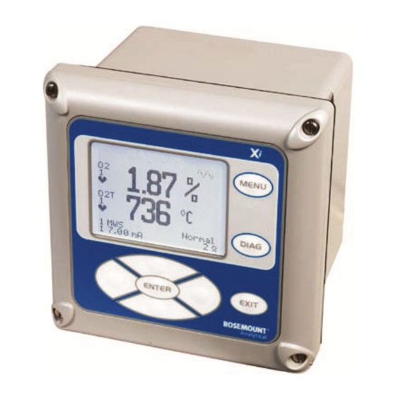
O Figure 4-1: Rosemount Xi display (typical) Note The display can be customized through the Rosemount Xi menu. Use the SYSTEM → CONFIGURE → MAIN DISPLAY path (Figure 4-2). - Page 29 4.1.2 Rosemount Xi Controls The Rosemount Xi can be used to change the software and alarm settings, to adjust the high and low gas settings, and to initiate the calibration sequence. Refer to the following control descriptions. Use the control keys on the front...
- Page 30 Quick Start Guide October 2022 Figure 4-2: Xi menu Rosemount Xi...
- Page 31 October 2022 Quick Start Guide Quick Start Guide...
- Page 32 Quick Start Guide October 2022 Rosemount Xi...
- Page 33 Password protection Beginning with Rosemount Xi system software version 1.05 or higher, the main display and diagnostic screens of the Rosemount Xi can be viewed at any time, but further access and unauthorized configuration changes can be prevented by enabling a password protection feature. However, the Rosemount Xi is shipped with password protection disabled.
- Page 34 4.2.1 Field communicator signal line connections When working at the Rosemount Xi, the Field Communicator can be connected directly to test points TP21 and TP22 on the Rosemount Xi I/O board as shown in Figure 4-3. The AM+ and AM- test points are provided to monitor the 4-20 mA signal without breaking into the loop.
- Page 35 October 2022 Quick Start Guide with a PC (refer to applicable HART documentation regarding HART/PC applications). In the online mode, the Field Communicator is connected to the 4-20 mA analog output signal line. The communicator is connected in parallel to the probe or in parallel to the 250 ohm load resistor.
-
Page 36: Safety Instructions For The Wiring And Installation Of This Apparatus
8. Where equipment or covers are marked with the following symbol, there is a danger from hot surfaces beneath. These covers should only be removed by trained service personnel when power is removed from the equipment. Certain surfaces may remain hot to the touch. Rosemount Xi... - Page 37 October 2022 Quick Start Guide 9. Where equipment or covers are marked with the following symbol, refer to the Reference Manual for instructions. 10. All graphical symbols used in this product are from one or more of the following standards: EN61010-1, IEC417, and ISO3864. 11.
-
Page 38: Certifications
Quick Start Guide October 2022 Certifications Rosemount Xi... - Page 39 October 2022 Quick Start Guide Quick Start Guide...
- Page 40 00825-0100-4889, Rev. AB October 2022 © 2022 Emerson. All rights reserved. The Emerson logo is a trademark and service mark of Emerson Electric Co. Rosemount is a mark of one of the Emerson family of companies. All other marks are the property of their respective...
Need help?
Do you have a question about the Rosemount Xi and is the answer not in the manual?
Questions and answers