
Related Manuals for Emerson Rosemount Analytical RDO


Summary of Contents for Emerson Rosemount Analytical RDO
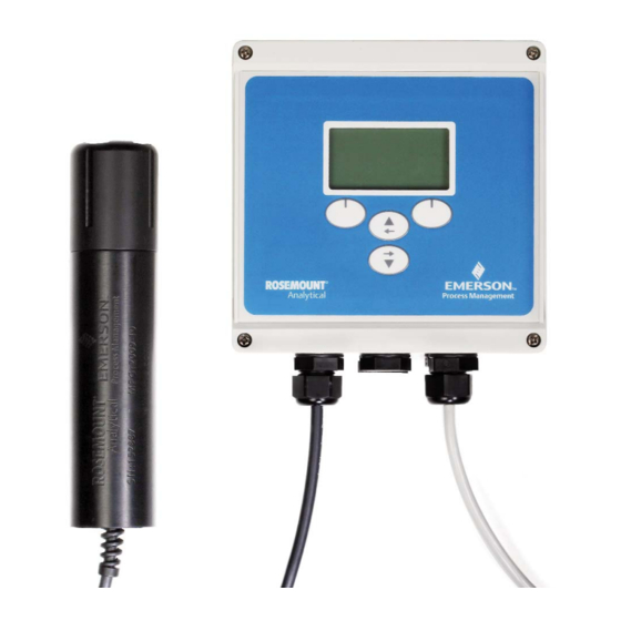
- Page 1 Manual 51-RDO Model RDO April 2010 ® Optical Dissolved Oxygen Analyzer and Sensor RDO is a registered trademark of In-Situ Inc. All rights reserved.
- Page 2 this page left blank intentionally...
-
Page 3: Table Of Contents
MODEL RDO TABLE OF CONTENTS TABLE OF CONTENTS No. Title Page Section 1: Installation ........................4 Box Contents..........................4 Optional Mounting Kit........................4 Mounting Options ...........................4 1.3.1 Analyzer Dimensions ........................4 1.3.2 Pole Mounting ..........................5 1.3.3 Wall Mounting Using Mounting Tabs .....................6 1.3.4 Wall Mounting With User-supplied Screws and Hardware ............6 Installing Dome Connectors and Plugs ..................7 Section 2: Wiring..........................8 Electro-static Discharge (ESD) Recommendations ..............8... - Page 4 Emerson Process Management makes no warranty of any kind with regard to this material, including, but not limited to, its fitness for a particular application.
-
Page 5: Section 1: Installation
MODEL RDO INSTALLATION SECTION 1.0 INSTALLATION 1.1 BOX CONTENTS 1.3 MOUNTING OPTIONS Remove the analyzer from the shipping box. The ship- 1.3.1 Analyzer Dimensions ping box should contain: • Figure 1-1 calls out the analyzer dimensions with • Analyzer (1) the lid closed. - Page 6 MODEL RDO INSTALLATION 1.3.2 Pipe Mounting 1. Remove the four nuts and four screws from the mounting kit. 2. Open the enclosure and drop one nut into each drilled corner of the box (Figure 1-3). 3. Use a screwdriver to push the nut down and set it in place (Figure 1-3).
-
Page 7: Wall Mounting Using Mounting Tabs
MODEL RDO INSTALLATION 1.3.3 Wall Mounting Using Mounting Tabs The optional mounting kit contains a set of wall mount- ing hardware that includes four screws, nuts, and tabs for mounting the analyzer to a wall or panel. Follow the instructions included with the mounting tab hardware to attach the tabs (Figure 1-6). -
Page 8: Installing Dome Connectors And Plugs
MODEL RDO INSTALLATION 1.4 INSTALLING DOME CONNECTORS 3. Place the lock nut concave side down on the AND PLUGS threads and using a screwdriver blade and mallet, tighten the lock nut until there is approximately one Install dome connectors and plugs as shown in Figure thread showing. -
Page 9: Section 2: Wiring
MODEL RDO WIRING SECTION 2.0 WIRING 2.3 ENSURING GOOD ELECTRICAL DANGER CONNECTIONS To ensure that all sensors and power sources function Only properly trained and qualified personnel properly, make sure that: should install the RDO analyzer described in this • Each individual wire is stripped and tinned to ¼... - Page 10 MODEL RDO WIRING The AC power board is located under the metal shield on the right side of the enclosure. The terminal strip on the board accommodates the AC power connections as well as two high voltage relay connections. See Figure 2-1. FIGURE 2-2.
- Page 11 MODEL RDO WIRING 2.5 ANALOG AND DIGITAL OUTPUTS AND LOW VOLTAGE RELAY CONNECTIONS DANGER Requires 24-12 AWG cable. Requires stripped and tinned ® RuggedCable system Requires stripped and tinned ® RuggedCable system Requires 24-12 AWG cable CONNEXIONS POUR AUTOMATE PROGRAMMABLE INDUSTRIEL DANGER Requires 24-12 AWG cable Débrancher toute alimentation à...
-
Page 12: Rdo Probe Wiring
MODEL RDO WIRING 2.6 RDO PROBE WIRING DANGER Make sure that power to the instrument is discon- nected before making any wiring connections. CONNEXIONS POUR LE RACORD DES SONDES FIGURE 2-4. Earth ground screws for DANGER analog outputs and sensors. Débrancher toute alimentation à... -
Page 13: Section 3: Placing The Rdo Probe In Service
MODEL RDO PLACING PROBE IN SERVICE SECTION 3.0 PLACING THE RDO PROBE IN SERVICE 3.1 UNPACKING 3. Align the arrow on the cap with the index mark on the probe and firmly press the cap onto the probe, Remove the probe and sensing cap from the box. The without twisting, until it seals. - Page 14 this page left blank intentionally...
-
Page 15: Section 4: Display And Operation
MODEL RDO DISPLAY AND OPERATION SECTION 4.0 DISPLAY AND OPERATION 4.1 DISPLAY AND KEYPAD Table 4.1 shows the icons used in the display. Figure 4-1 shows the keypad and display window. Table 4-1 Display icons and their descriptions Error with parameter Calibration stabilizing Calibration nominally stable View... - Page 16 this page left blank intentionally...
-
Page 17: Section 5: Programming The Analyzer
MODEL RDO PROGRAMMING THE ANALYZER SECTION 5.0 PROGRAMMING THE ANALYZER 5.1 INITIAL CONFIGURATION b. Use the Up/Left Arrow key to enter a positive or negative value. Enter the following information upon first use or any- c. Press the Down/Right arrow key to move the time after you have restored the default settings. -
Page 18: Parameters (Concentration, Temperature, Saturation, And Partial Presssure)
MODEL RDO PROGRAMMING THE ANALYZER FIGURE 5-1. Menu Tree 1. Select Menu, then Settings, then Probes. Select • Enable or disable the measurement. If the meas- RDO Probe A or RDO Probe B, if it is present, then urement is enabled, the probe will make the meas- Select Options. -
Page 19: Replacing A Probe
MODEL RDO PROGRAMMING THE ANALYZER as soon as you press any key to leave. 5.3.4 Deleting a Probe d. Scroll to Sentinel and press Select. Use the If you plan to permanently remove a probe, follow the arrow keys to change the setting. steps below. -
Page 20: Configuring Outputs
MODEL RDO PROGRAMMING THE ANALYZER 3. Select Temperature 8. Scroll to 20mA Trim: Use the arrow keys to adjust the loop current to 20 mA. a. Press the Select key to toggle between enable and disable. If the box is checked, temperature 5.5.2 Alarm Relays has been selected. -
Page 21: Changing The Date And Time
MODEL RDO PROGRAMMING THE ANALYZER 4. Scroll to Mode and select it. Choose high alarm or 1. Select Menu, then Settings, then Power Save. low alarm. 2. Select External. Do not choose Battery. 5. Scroll to Parameter and select it. Scroll through the 3. -
Page 22: Defaults
MODEL RDO PROGRAMMING THE ANALYZER You may set up the analyzer with passwords for an 5.14 DIAGNOSTICS administrator and a user. The user can access the The following diagnostic information is available for the Calibrate, Hold Options, and Diagnostics menus. The RDO probe: administrator can access all functions, most notably, •... -
Page 23: Calibration Options
MODEL RDO CALIBRATION SECTION 6.0 CALIBRATION 6.1. CALIBRATION OPTIONS There are three ways to calibrate the RDO probe: • Saturation: Both a two-point (100% and 0% satura- tion) and one-point (100% saturation) calibration are available. 100% saturation refers to water com- pletely saturated with atmospheric oxygen. -
Page 24: Two-Point Calibration (100% And 0% Saturation)
MODEL RDO CALIBRATION 5. Allow at least 5 minutes for the temperature to stabi- 4. The 0% saturation step starts automatically. lize before starting the calibration. Keeping the sen- Remove the probe and fill the calibration chamber to sor in the shade will help reduce drift caused by the the upper fill line with approximately 60 mL of fresh sun’s heat. -
Page 25: Concentration Calibration
MODEL RDO CALIBRATION 7. The calibration report screen appears. The slope will be between 0.8 and 1.2 and the offset will be between -0.2 an +0.2. Press OK. 8. Remove the probe from the calibration chamber. Rinse it and return it to the process liquid. 6.4 CONCENTRATION CALIBRATION 1. - Page 26 this page left blank intentionally...
-
Page 27: Section 7: Maintenance
MODEL RDO MAINTENANCE SECTION 7.0 MAINTENANCE 7.1 ANALYZER 2. Gently scrub the probe body with a soft-bristled brush or a nylon dish scrubber. Use a mild detergent 7.1.1 Cleaning the analyzer enclosure to remove oil or grease. Soak in vinegar followed by Clean the analyzer case and front panel by wiping with deionized water to remove mineral deposits or ex- a clean, soft cloth dampened with water ONLY. - Page 28 MODEL RDO MAINTENANCE 7.3 REPLACEMENT PARTS Part number Description R0094030 RDO analyzer, AC power, no data logging R0086460 RDO sensor with 32 ft (10 m) of integral cable R0082490 RDO sensor with twist lock connector R0087560 RDO analyzer pipe and wall mounting kit R00CBL10 Twist lock connector cable, 32 ft (10 m) R00CBL20...
- Page 29 MODEL RDO SPECIFICATIONS SECTION 8.0 SPECIFICATIONS 8.1 RDO PROBE 8.2 RDO ANALYZER Wetted Materials: Delrin , ABS, Viton , titanium, polycar- Enclosure: Polycarbonate, rated NEMA 4X, IP67 bonate/poly(methyl methacrylate) blend Dimensions (W x H x D): 6.3 x 6.3 x 3.6 in (16 x 16 x Dimensions: length 8.0 in (203 mm) diameter 1.9 in 9.0 cm) (47 mm)
- Page 30 this page left blank intentionally...
- Page 31 this page left blank intentionally...
- Page 32 ON-LINE ORDERING NOW AVAILABLE ON OUR WEB SITE right now. http://www.raihome.com Specifications subject to change without notice. Credit Cards for U.S. Purchases Only. Sira MC070110/00 Emerson Process Management 2400 Barranca Parkway Irvine, CA 92606 USA Tel: (949) 757-8500 Fax: (949) 474-7250 http://www.raihome.com...
Need help?
Do you have a question about the Rosemount Analytical RDO and is the answer not in the manual?
Questions and answers