
Related Manuals for Emerson Rosemount 3814


Summary of Contents for Emerson Rosemount 3814
- Page 1 Maintenance and Troubleshooting Manual 00809-0100-3814, Rev AB January 2023 Rosemount ™ 3814 Liquid Ultrasonic Flow Meter...
- Page 2 Emerson employees. Emerson will not accept your returned equipment if you fail to follow Emerson procedures. Return procedures and forms are available on our web support site at www.emerson.com, or by phoning the Emerson Customer Service department.
-
Page 3: Table Of Contents
3.4 Transducer cable removal and installation................55 3.5 Replace the meter electronics....................61 Appendix A Conversion factors....................77 A.1 Conversion factors per units of measurement..............77 A.2 K-Factor and inverse K-Factor....................78 Appendix B Engineering drawings..................... 79 B.1 Rosemount 3810 Series Ultrasonic Flow Meter Drawings...........79 Rosemount 3814 Liquid Ultrasonic Flow Meter... - Page 4 Contents Maintenance and Troubleshooting Manual January 2023 00809-0100-3814 Emerson.com/Rosemount...
-
Page 5: Chapter 1 Routine Maintenance
00809-0100-3814 January 2023 1 Routine Maintenance 1.1 Meter maintenance This section includes discussion of the maintenance of Rosemount 3814 Liquid Ultrasonic Flow Meters. For reference, you may download the MeterLink Quick Start Manual from: www.emerson.com/meterlink CAUTION SURFACE TEMPERATURE HAZARD Meter body and piping may be extremely hot or cold. -
Page 6: Field Hydrostatic Pressure Testing Procedures
A. Flange stabilizers CAUTION ESCAPING FLUIDS HAZARD The purchaser of the meter is responsible for the selection of Emerson components/seals and materials compatible with the chemical properties of the measurement fluid. Failure to select suitable meter components/seals may cause escaping fluids, resulting in injury to personnel or equipment damage. -
Page 7: Routine Maintenance
Preferably, collect the log files at several velocities within the operating range of the meter. This helps establish that the flow profile is relatively constant throughout the meters operating range (except velocities below 3 ft/sec where the profile may vary). Rosemount 3814 Liquid Ultrasonic Flow Meter... - Page 8 Trending the logs indicates changes from the original installation of the meter, or over time. Looking at a single inspection report, that is either collected monthly or quarterly, can give you an indication of the meter's health. Emerson.com/Rosemount...
- Page 9 Daily log - generated every 24 hours on the Contract Hour. • Hourly log - generated every hour at the top of the hour. • Event log - collects the alarm and event log records. Rosemount 3814 Liquid Ultrasonic Flow Meter...
- Page 10 Maintenance and Troubleshooting Manual January 2023 00809-0100-3814 Figure 1-4: Archive log collection parameters The logs may be collected in a single file or you can choose to collect one type of log. Each of the Meter Archive logs include the Meter Configuration file. Emerson.com/Rosemount...
- Page 11 1.3.3 High Viscosity piping requirements The piping requirements for High Viscosity meter applications are shown in Figure 1-5. Rosemount 3814 Liquid Ultrasonic Flow Meter...
- Page 12 Rosemount recommendations. Alignment of this flange joint is critical in the performance of the meter. It is recommended to consult Emerson Customer Support for assistance when re-aligning this joint.
-
Page 13: Chapter 2 Troubleshooting
Status Summary screen. The alarms are shown with the primary causes listed first. Click the question mark, , next to the alarm to display a help topic related to the alarm and recommended actions to resolve the issue. Figure 2-2: Status Summary Rosemount 3814 Liquid Ultrasonic Flow Meter... - Page 14 The System alarm indicates a failure in the hardware that should be addressed by a service technician. This includes memory checksum errors and communication errors within the hardware. A Red LED indicates a System alarm condition. Collect a Maintenance log and an audit/alarm log and then, contact your Emerson Flow service representative. Emerson.com/Rosemount...
- Page 15 Red and green are the only colors used for this alarm. 2.1.7 Communications The Communications Analyzer (via MeterLink Tools → Menu → Communications Analyzer menu path) displays communications between MeterLink and the ultrasonic meter. This utility is useful for troubleshooting communications to the Rosemount 3814 Liquid Ultrasonic Flow Meter...
-
Page 16: Troubleshooting The Meter
Replace the Acquisition Module. — If the Acquisition Module cannot be reprogrammed, collect a complete Archive log and contact your local area Emerson Flow service representative. Acquisition Module is not • Upgrade the firmware in the meter to the latest compatible with firmware version using MeterLink. - Page 17 Check the CPU Module LED1 is on (either solid red or flashing green). If the LED is not on, check power to the meter. — If the LED is on, check the Ethernet cable connections. Rosemount 3814 Liquid Ultrasonic Flow Meter...
- Page 18 PC is configured to receive its IP address automatically (via DHCP). Communication line • Check for loose connections at the flow meter and the connected to the flow flow computer. computer but no signal is • Check the CPU Module settings. received Emerson.com/Rosemount...
- Page 19 Verify that the resistance of transducers is within but all chords display failures specification (2 Ω). • Check the Acquisition Board. • Check the interconnect cables between the Base Enclosure and the Transmitter Electronics Enclosure. Rosemount 3814 Liquid Ultrasonic Flow Meter...
- Page 20 Verify that the communication parameters of the MeterLink program are correctly set. • Check RS-485 or RS-232 communication. Cannot communicate with Refer to the Emerson 475 Field Communication User’s 475 Field Communicator Manual, Rev F. This manual may be downloaded from the following location: www.emerson.com/en-us/catalog/ams-475-field-...
- Page 21 65 °C, you must remote mount the electronics off of the meter body. • Collect a Maintenance log using MeterLink while the meter is experiencing the issue and contact your Emerson Flow service representative. Rosemount 3814 Liquid Ultrasonic Flow Meter...
- Page 22 If using an analog pressure device, recheck wiring and switch settings. — If a flow computer is writing values to the fixed flow pressure, verify that the flow computer is still writing valid values without Modbus write errors. — Re-verify the pressure input settings are correct. Emerson.com/Rosemount...
- Page 23 If this occurs, contact Emerson Flow Support for assistance. No power to the unit • Check for correct voltage (24 VDC) (refer to the System...
- Page 24 1 (none) 2, 4, 8, or 16). If increasing the StackSize is not successful, try turning on the filter or consult with Emerson Customer Support if you are unsure of how stacking a signal can affect the meter's operation.
- Page 25 If you wish to use the Monitor (Detailed) dialog as the default view, click the checkbox in the lower portion of the dialog box. Figure 2-5: Meter Monitor (Detailed) view The following details the information displayed in this dialog box. Rosemount 3814 Liquid Ultrasonic Flow Meter...
- Page 26 This indicates an active alarm. Resolve and acknowledge active alarms as displayed on the Status Summary page. Click the Help button, , beside the alarm description to display information about the alarm and recommended actions to resolve the issue. Emerson.com/Rosemount...
- Page 27 Noise Ratios (SNR) are displayed in decibels and should be compared to the initial values in the maintenance logs taken during the calibration or initial start-up. • The average chord signal amplitudes should be compared to the Rosemount 3814 Liquid Ultrasonic Flow Meter...
- Page 28 If present, resolve transducer issues (failed transducer, cabling or debris buildup on the transducer face, or path length configured incorrectly). • Adjust SSMin or SSMax only if other checks pass (consult a Emerson Flow Service representative before making these adjustments). Emerson.com/Rosemount...
- Page 29 MeterLink Tools Menu • Frequency output • Run the Frequency Outputs test • If the output reads zero, you may require a pull up resistor 1.2k OHM, 0.5 Rosemount 3814 Liquid Ultrasonic Flow Meter...
- Page 30 Warm start: start required — Collect an Archive event log (Audit log) using MeterLink to view configuration parameter changes and when they changed. • Warm start is required: — When you make changes to the transducer characteristics, sample rates, the Emerson.com/Rosemount...
- Page 31 Power failure • If this was a known Menu power fail or restart of the meter just acknowledge this alarm on the Status Summary page. • If this was an unexpected restart of the meter, Rosemount 3814 Liquid Ultrasonic Flow Meter...
- Page 32 11-36 VDC at the meter. • Collect a complete Archive log and contact your local area Emerson Flow service representative. MeterLink Meter Monitor • Chord failure MeterLink • The meter is unable (Summary) view...
- Page 33 COM port. Typically this will only be necessary if you use one COM port to talk direct (serial communications) and use the same COM port to connect to an external modem. This is an apparent limitation in Microsoft’s Dial-up ® Rosemount 3814 Liquid Ultrasonic Flow Meter...
-
Page 34: Troubleshoot Maintenance Log Files And Trend Files
The only work around is to only install one modem driver per COM port on the PC at a time. Refer to the MeterLink Quick Start Manual (00809-0100-7630) for phone and modem details. The manual may also be downloaded from the Emerson website. www.emerson.com/meterlink 2.2.3 ... - Page 35 MeterLink, select Options under the File menu. ® Under the Trust Center tab, click Trust Center Settings. Under the Macro Settings tab, select Trust access to the VBA project object model. Rosemount 3814 Liquid Ultrasonic Flow Meter...
-
Page 36: Meter Reset Mode
5. Connect to the meter again using the default administrator username and go to Meter → Manage Users to setup new users and change the default password for the administrator user. • For added security, the default username for the administrator user can be changed as well. Emerson.com/Rosemount... - Page 37 Maintenance and Troubleshooting Manual Troubleshooting 00809-0100-3814 January 2023 • If a Cold start meter operation was performed, you must reconfigure the meter from a previously saved configuration file using the Edit → Compare Configuration screen. Rosemount 3814 Liquid Ultrasonic Flow Meter...
- Page 38 Troubleshooting Maintenance and Troubleshooting Manual January 2023 00809-0100-3814 Emerson.com/Rosemount...
-
Page 39: Chapter 3 Meter Maintenance
Failure to comply may cause injury to personnel. NOTICE Prior to lifting the unit, refer to the Rosemount 3814 Liquid Ultrasonic Flow Meter nameplate or outline dimensional (general arrangement) drawing for the assembled weight. Rosemount 3814 Liquid Ultrasonic Flow Meter... - Page 40 FLUID CONTENTS MAY BE UNDER PRESSURE When the meter is under pressure, DO NOT attempt to remove or adjust the transducer housing. Attempting to do so may release pressurized fluid, resulting in serious injury for personnel or equipment damage. Emerson.com/Rosemount...
- Page 41 Failure to do so could allow the meter to roll, resulting in serious injury or equipment damage. Consult your Emerson Sales and Service representative to ensure you purchase the correct components and seals for your application, below safety message. Rosemount 3814 Liquid Ultrasonic Flow Meter...
-
Page 42: Transducer Field Removal And Installation
Rosemount 3810 Series Ultrasonic Flow Meters are supplied with transducers which are extractable while the line is pressurized. The transducer shown below is a one-piece capsule that can be easily installed or removed from the meter without depressurizing the meter. Figure 3-2: Transducer (LT-01/LT-04/LT-08) Figure 3-3: Transducer (LT-03/LT-05/LT-09) Emerson.com/Rosemount... - Page 43 Transducer removal and installation WARNING CUTTING HAZARD Sharp edges may be present on the meter. Wear appropriate personal protective equipment when working on the meter. Failure to do so may cause serious injury. Prerequisites Tools required: Rosemount 3814 Liquid Ultrasonic Flow Meter...
- Page 44 Nickel anti-seize compound ® Procedure 1. Before removing and installing transducer(s), connect to the meter using MeterLink and collect and save a Maintenance Log and configuration files. Dow Corning 111 and Dow Corning 200 are trademarks of Dow Corning Corporation, U.S.A. Emerson.com/Rosemount...
- Page 45 Ensure the transducer housing threads are properly aligned (avoid cross- threading the housing) with the meter body, then use a wrench on the 1 inch hex bolt, if necessary, to screw it down until it is flush with the Rosemount 3814 Liquid Ultrasonic Flow Meter...
-
Page 46: Transducer Housing Removal And Installation
Rosemount 3810 Series Ultrasonic Flow Meters utilize transducer housings that contain the transducer and act as the pressure barrier between the transducers and the fluid. Under normal maintenance such as transducer replacement, the transducer housings do not need to be removed. If it is necessary to remove the Emerson.com/Rosemount... - Page 47 The meter must be fully depressurized and drained before attempting to remove the transducer housing. If fluid begins to leak from the transducer housing, immediately reinstall it. Failure to do so may cause serious injury or equipment damage. Rosemount 3814 Liquid Ultrasonic Flow Meter...
- Page 48 Correct the issue before attempting to remove the housing again. 6. Any time a transducer housing is removed from the meter the O-rings must be replaced with new O-rings prior to reinstalling the housing in the meter. Emerson.com/Rosemount...
- Page 49 Also, ensure the transducer housing is fully seated against the meter body per the table below 20 ft-lb (27 N-m). Rosemount 3814 Liquid Ultrasonic Flow Meter...
- Page 50 (see Figure 3-10). 15. Apply power to the meter and slowly repressurize the meter to line pressure. Check for leaks as the meter is pressurized. If you hear or see Emerson.com/Rosemount...
- Page 51 This utility is only available while connected to a meter. The length of the meter body is found on the original calibration sheet supplied with the meter. Rosemount 3814 Liquid Ultrasonic Flow Meter...
- Page 52 When transducer pairs are replaced or the meter has performed a cold start, the corresponding meter calibration parameters must be updated for accurate operation. Select the chord parameters which have changed (see Figure 3-12, example: Transducers and Housings are selected). Emerson.com/Rosemount...
- Page 53 Enter the chord values for the removed components, the components added and the new Delay time and Delta time on this page. After the values are entered, click the Write to Meter button to apply the changes. Rosemount 3814 Liquid Ultrasonic Flow Meter...
- Page 54 Equation 3-2. The lengths of the transducer housings are etched on on the individual components. The length of the meter body is found on the original calibration sheet supplied with the meter. Emerson.com/Rosemount...
-
Page 55: Transducer Cable Removal And Installation
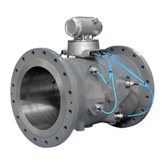
Figure 3-14: Flow meter transducer cables and ports A. Base enclosure transducer cable glands B. Cable ties (two locations) C. 3814 Ultrasonic Meter transducer port and locking ring D. Transducer mount and transducer cable Rosemount 3814 Liquid Ultrasonic Flow Meter... - Page 56 B. Transducer retainer to locking ring security wire 3. Unscrew the cable nut from the transducer housing and then, pull the cable from the transducer housing (see Figure 3-4). 4. Cut the tie wraps for the transducer cable you are replacing. Emerson.com/Rosemount...
- Page 57 Failure to do so could allow the meter to roll, resulting in serious injury or equipment damage. 9. Use a 1/8 inch (3 mm) flat-blade screw driver and disconnect the transducer wiring terminal block from the Acquisition Module (see Figure 3-17). Rosemount 3814 Liquid Ultrasonic Flow Meter...
- Page 58 Leave the connector plugged into the Acquisition Module while terminating the individual wires. 17. Once the transducers are wired correctly, tighten the cable gland so that the transducer cable is held securely in place. Pull the cable back through Emerson.com/Rosemount...
- Page 59 Choose holes that minimize counterclockwise rotation of the end cap when the security wire is taut (maximum wire diameter 0.078 inch; 2.0 mm). Dow Corning 111 and Dow Corning 200 are trademarks of Dow Corning Corporation, U.S.A. Rosemount 3814 Liquid Ultrasonic Flow Meter...
- Page 60 B. Security wire seals 30. Adjust the security wire, removing all slack and thread into the lead seal. 31. Crimp seal and cut wire ends to remove excess wire. 32. If required, attach the security wire seals on the Base Enclosure. Emerson.com/Rosemount...
-
Page 61: Replace The Meter Electronics
The Rosemount 3810 Series Ultrasonic Flow Meter Transmitter Electronics ™ Enclosure consists of the following: • CPU Module assembly (P/N 1-360-03-014) • Optional I/O Module (RS-232 or RS-485) • I.S. Barrier Board (P/N 1-360-03-004) Rosemount 3814 Liquid Ultrasonic Flow Meter... - Page 62 3. Disconnect security seals on the Transmitter Electronics Enclosure (see Figure 3-6), loosen the end cap security latches using a 3 mm Allen wrench (see Figure 3-20 and remove both end caps from the Transmitter Electronics Enclosure. Emerson.com/Rosemount...
- Page 63 Choose holes that minimize counterclockwise rotation of the end cap when the security wire is taut (maximum wire diameter 0.078-in.; 2.0 mm). Rosemount 3814 Liquid Ultrasonic Flow Meter...
- Page 64 Acquisition Module replacement before replacing the end caps and sealing the enclosure. This completes the CPU Module or I/O Module replacement procedure. If you encounter problems with this procedure, see the Emerson Customer Support contact information in Emerson website: www.emerson.com 3.5.2 ...
- Page 65 11. Adjust the security wire, removing all slack and thread into the lead seal. 12. Cut wire ends to remove excess wire. 13. Apply power to the meter. This completes the fuse replacement procedure. Rosemount 3814 Liquid Ultrasonic Flow Meter...
- Page 66 6. Pull the Backplane board out of the enclosure. This disconnects the I.S. Barrier Board. Lay the Backplane board down with the Acquisition Cable still attached (the Power Supply board may remain attached to the Backplane when you remove it from the enclosure). Emerson.com/Rosemount...
- Page 67 12. Install the four Phillips head screws to secure the Backplane to the enclosure standoffs. 13. Reinstall the terminal blocks on the CPU Module, Optional I/O Module (if installed), and the Power Supply board using a 3 mm flat head screw driver. Rosemount 3814 Liquid Ultrasonic Flow Meter...
- Page 68 18. Cut wire ends to remove excess wire. 19. Apply power to the meter. This completes the Backplane Board replacement procedure. If you encounter problems with this procedure, see the Emerson Customer Support contact information in Emerson website: www.emerson.com I.S. Barrier Board replacement Procedure 1.
- Page 69 14. If replacing other electronics, continue with the following procedures before replacing the end caps and sealing the enclosure. 15. If you are not replacing other electronics, replace the end caps and security latches (3 mm Allen wrench required). Rosemount 3814 Liquid Ultrasonic Flow Meter...
- Page 70 17. Cut wire ends to remove excess wire. 18. Apply power to the meter. This completes the I.S. Barrier Board replacement procedure. If you encounter problems with this procedure, see the Emerson Customer Support contact information in Emerson website: www.emerson.com...
- Page 71 13. If you are not replacing other electronics, replace the Transmitter Electronics Enclosure end caps, install the end cap security latches (3 mm Allen wrench required). Rosemount 3814 Liquid Ultrasonic Flow Meter...
- Page 72 15. Cut wire ends to remove excess wire. 16. Apply power to the meter. This completes the Power Supply Board replacement procedure. If you encounter problems with this procedure, see the Emerson Customer Support contact information in Emerson website: www.emerson.com...
- Page 73 C. Base enclosure 6. Use a 1/8 inch (3 mm) flat head screw driver and disconnect the Acquisition cable terminal block and the transducer wire terminal blocks from the Acquisition Module inside of the Base enclosure. Rosemount 3814 Liquid Ultrasonic Flow Meter...
- Page 74 13. If required, install the security seal wire into and through one of the two holes in the end cap. Choose holes that minimize counterclockwise rotation of the end cap when the security wire is taut (maximum wire diameter 0.078 inch; 2.0 mm) (see Figure 3-22). Emerson.com/Rosemount...
- Page 75 16. Apply conduit sealing compound according to manufacturer’s recommendations. 17. Apply power to the meter. This completes the Acquisition Module replacement procedure. If you encounter problems with this procedure, see the Emerson Customer Support contact information in Emerson website: www.emerson.com Rosemount 3814 Liquid Ultrasonic Flow Meter...
- Page 76 Meter maintenance Maintenance and Troubleshooting Manual January 2023 00809-0100-3814 Emerson.com/Rosemount...
-
Page 77: Appendix A Conversion Factors
Conversion factors per units of measurement The following table includes conversion factors for many of the Metric and U.S. Customary units of measure used with Rosemount 3814 Liquid Allocation Ultrasonic Flow Meters and MeterLink ™ Table A-1: Conversion factors per units of measurement... -
Page 78: K-Factor And Inverse K-Factor
= 60 s/m • volume/hour = 3600 s/h • volume/day = 86400 s/d (**) Volume = where the volume is selected via data points: • Units System • VolUnitUS — gallons — barrels • VolUnitMetric — cubic meters — liters Emerson.com/Rosemount... -
Page 79: Appendix B Engineering Drawings
00809-0100-3814 January 2023 B Engineering drawings B.1 Rosemount 3810 Series Ultrasonic Flow Meter Drawings This appendix contains the following engineering drawing(s) for the ultrasonic meter: DMC-004936 Rosemount 3810 Liquid Ultrasonic Flow Meter System Wiring Diagram Rosemount 3814 Liquid Ultrasonic Flow Meter... - Page 80 Engineering drawings Maintenance and Troubleshooting Manual January 2023 00809-0100-3814 Emerson.com/Rosemount...
- Page 81 Maintenance and Troubleshooting Manual Engineering drawings 00809-0100-3814 January 2023 Rosemount 3814 Liquid Ultrasonic Flow Meter...
- Page 82 Emerson Terms and Conditions of Sale are available upon request. The Emerson logo is a trademark and service mark of Emerson Electric Co. Rosemount is a mark of one of the Emerson family of companies. All other marks are the property of their respective owners.
Need help?
Do you have a question about the Rosemount 3814 and is the answer not in the manual?
Questions and answers