Sign In
Upload
Manuals
Brands
Emerson Manuals
Measuring Instruments
Rosemount Analytical X-STREAM XEGP
Emerson Rosemount Analytical X-STREAM XEGP Manuals
Manuals and User Guides for Emerson Rosemount Analytical X-STREAM XEGP. We have
1
Emerson Rosemount Analytical X-STREAM XEGP manual available for free PDF download: Short Form Manual
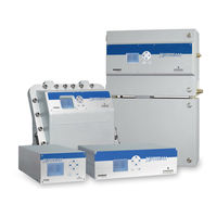
Emerson Rosemount Analytical X-STREAM XEGP Short Form Manual (123 pages)
Gas Analyzers
Brand:
Emerson
| Category:
Measuring Instruments
| Size: 12.26 MB
Table of Contents
Table of Contents
3
Introduction
7
Terms Used in this Instruction Manual
8
Symbols Used on and Inside the Equipment
9
Symbols Used in this Manual
10
Additional Literature
11
General Safety Notice / Residual Risk
11
Intended Use Statement
11
Definitions
7
Safety Instructions
11
Authorized Personnel
12
Disposal of Batteries
12
Installing and Connecting this Analyzer
13
Operating and Maintaining this Analyzer
13
Chapter 1 Technical Description
19
Overview
20
Housings
20
The Front Panel
20
Interfaces
21
Fig. 1-1: X-STREAM XE Front Panel (here the X-STREAM XEGP)
21
Comparison of the Various X-STREAM Analyzer Model
22
X-STREAM XEGK: ½ 19 Inch Table-Top Unit
24
Fig. 1-2: X-STREAM XEGK
25
X-STREAM XEGP: 19 Inch Table-Top or Rackmount Design
26
Fig. 1-3: X-STREAM XEGP - Details
27
X-STREAM XEXF: Field Housing with Single (XEF) or Dual (XDF) Compartment
28
Fig. 1-4: X-STREAM XEF / XDF- Front Views
29
Fig. 1-5: X-STREAM XEF - Side and Bottom View
30
Fig. 1-6: X-STREAM XEF - Power Supply and Signal Terminals
30
XEXF Field Housings for Installation in Hazardous Areas (Ex-Zones)
31
Measurement Specifications
32
Tab. 1-1: Gas Components and Measuring Ranges, Examples
32
Tab. 1-2: IR, UV, VIS, TCD - Standard and Enhanced Measurement Performance
33
Tab. 1-3: Trace Moisture - Standard Measurement Performance Specifications
33
Tab. 1-4: Oxygen - Standard and Enhanced Measurement Performance Specifications
34
Tab. 1-5: H S - Standard Measurement Performance Specifications
34
Tab. 1-7: Special Performance Specifications for Gas Purity Measurements
36
Chapter 2 Installation
37
Scope of Supply
37
Fig. 2-1: X-STREAM XE Analyzers - Scope of Supply
37
Introduction
38
Technical Data
39
Common Technical Data
39
Specific Technical Data
40
Gas Conditioning
41
Gas Connections
43
Fig. 2-3: Installation in Bypass Mode
44
Fig. 2-2: Labelling of Gas Connectors (Example)
44
Electrical Connections
45
X-Stream Xegk, X-Stream Xegp
47
Fig. 2-4: X-STREAM XEGK - Rear Panel
47
Fig. 2-5: X-STREAM XEGP - Rear View
48
Fig. 2-6: X-STREAM XEGP - Dimensions
49
Fig. 2-8: Power Supply Connectors
51
X-Stream Xexf
52
Fig. 2-9: X-STREAM XEF - Dimensions for Installation
52
Fig. 2-10: X-STREAM XDF - Dimensions for Installation
53
Fig. 2-11: X-STREAM XEXF Field Housings - Arrangement of Terminals, Cable Glands and
54
Fig. 2-12: Terminal Block X1 - Analog Signals and Relay Outputs 1-4 (XSTA)
57
Fig. 2-13: Power Supply Connections
58
Notes on Wiring Signal Inputs and Outputs
60
Electrical Shielding of Cables
60
Fig. 2-14: Shielded Signal Cable, Shielding Connected at both Ends
60
Fig. 2-15: Shielded Signal Cable, Shielding Connected at One End
60
Fig. 2-16: Signal Cable with Double Shielding, Shieldings Connected at Alternate Ends
61
Fig. 2-17: Shield Connector Terminal with Cable
61
Wiring Inductive Loads
62
Driving High-Current Loads
62
Fig. 2-18: Suppressor Diode for Inductive Loads
62
Fig. 2-19: Driving High-Current Loads
62
Driving Multiple Loads
63
Fig. 2-20: Loads in Series
63
Fig. 2-21: Loads in Parallel
63
Chapter 3 Startup
65
Introduction
65
Performing a Leak Test
66
Symbols and Typographical Conventions
67
Front Panel Elements
68
Display
68
Status Line and Text Message Line
68
Fig. 3-2: X-STREAM XE Front Panel
68
Keys
69
Software
71
Access Levels & Codes
74
Special Messages
75
Powering up
75
Boot Sequence
75
Measurement Display
76
Language Settings
77
Checking the Settings
78
Installed Options
79
Configuring the Display
80
Calibration Setup
81
Setting the Analog Outputs
83
Tab. 3-1: Analog Output Signals
84
Tab. 3-2: Analog Output Signals Settings and Operational Modes
86
Setting Concentration Alarms
88
Fig. 3-3: Arrangement of Concentration Thresholds
88
Backup the Settings
89
Web Browser
91
Connection Via Network
91
Fig. 3-4: Ethernet Connectors
91
Connection to Single Computer
92
Fig. 3-5: Web Browser Logon Screen
93
Fig. 3-6: Web Browser Measurements Screen
93
Chapter 4 Maintenance
95
Perform a Calibration
95
Preparing Calibrations
97
Manual Zero Calibration
99
Manual Span Calibration
101
Chapter 5 Dismounting and Disposal
102
Dismounting and Diposal of the Analyzer
102
Appendix
104
Block Diagram
104
Assignment of Terminals and Sockets
104
Tabletop & Rack Mount Analyzers
120
Field Housings
121
Advertisement
Advertisement
Related Products
Emerson Rosemount Apex
Emerson Rosemount Apex Sentry
Emerson Rosemount Analytical X-STREAM Enhanced Series
Emerson Rosemount Analytical X-STREAM XEGK
Emerson Rosemount Analytical X-STREAM XEXF
Emerson Rosemount Analytical X-STREAM XEFD
Emerson Rosemount Analytical RDO
Emerson Rosemount Analytical FCLi
Emerson Rosemount Analytical 385+
Emerson ROSEMOUNT X-STREAM XEGP
Emerson Categories
Controller
Control Unit
Transmitter
Measuring Instruments
Fan
More Emerson Manuals
Login
Sign In
OR
Sign in with Facebook
Sign in with Google
Upload manual
Upload from disk
Upload from URL