
Related Manuals for Emerson Rosemount Analytical FCLi


Summary of Contents for Emerson Rosemount Analytical FCLi
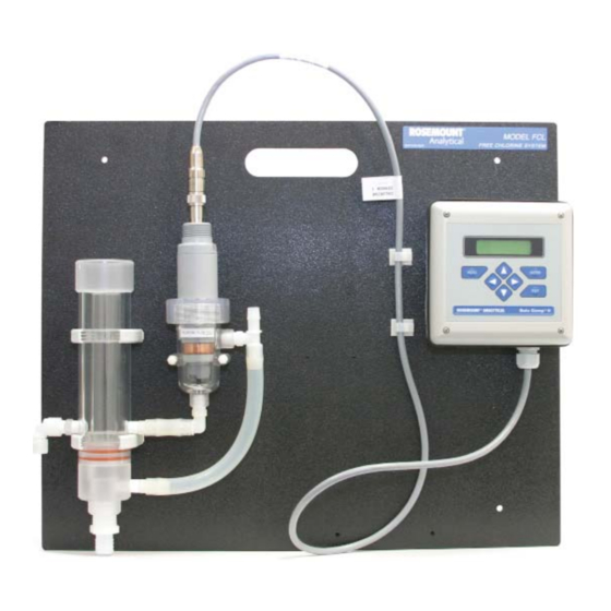
- Page 1 Instruction Manual PN 51-FCLi/rev.C March 2012 Model FCLi Free Chlorine Measuring System...
- Page 2 This product is not intended for use in the light industrial, residential or commercial environments per the instru- ment’s certification to EN50081-2. Emerson Process Management 2400 Barranca Parkway Irvine, CA 92606 USA Tel: (949) 757-8500 Fax: (949) 474-7250 http://www.rosemountanalytica.com...
- Page 3 QUICK START GUIDE FOR FCLi ANALYZER 1. Refer to Section 2.0 for installation instructions, and Section 3.0 for wiring instructions. 2. Once connections are secured and verified, apply power to the analyzer. 3. When the analyzer is powered up for the first time, Quick Start screens appear. Using Quick Start is easy. a.
-
Page 5: Table Of Contents
MODEL FCLi TABLE OF CONTENTS MODEL FCLi SYSTEM FOR THE DETERMINATION OF FREE CHLORINE TABLE OF CONTENTS Section Title Page DESCRIPTION AND SPECIFICATIONS ..............Features........................Specifications ......................Ordering Information ....................INSTALLATION ....................... Unpacking and Inspection..................Installation........................ WIRING........................Power, Alarm, and Output Wiring................Sensor Wiring ...................... - Page 6 MODEL FCLi TABLE OF CONTENTS TABLE OF CONTENTS CONT’D Section Title Page CALIBRATION ......................Introduction ......................Calibrating Temperature................... Calibration - Free Chlorine..................Auto Calibration - pH....................Manual Calibration - pH ................... Standardization - pH ....................Entering a Known Slope - pH................... MAINTENANCE .....................
- Page 7 MODEL FCLi TABLE OF CONTENTS LIST OF FIGURES Number Title Page Chlorine Sensor Parts ....................FCLi-01 ........................FCLi-2 ........................Wiring Connections ....................Wiring Diagram for Chlorine Sensor................. Wiring Diagram for Chlorine pH Sensor Combination..........Displays During Normal Operation................FCLi Keypad ......................Assigning Outputs 1 and 2 ..................
- Page 8 Date Notes 5/06 This is the initial release of the product manual. The manual has been reformatted to reflect the Emerson documentation style and updated to reflect any changes in the product offering. 3/07 Corrected typographical and format errors. 03/12...
-
Page 9: Description And Specifications
MODEL FCLi SECTION 1.0 DESCRIPTION AND SPECIFICATIONS SECTION 1.0. DESCRIPTION AND SPECIFICATIONS 1.1 APPLICATIONS AND FEATURES 1.2 SPECIFICATIONS 1.3 ORDERING INFORMATION AND ACCESSORIES • COMPLETE SYSTEM INCLUDES sensor, connecting cable, analyzer, and flow controller • SENSOR RESPONSE IS PRACTICALLY INDEPENDENT of pH between pH 6 and 10 •... -
Page 10: Specifications
MODEL FCLi SECTION 1.0 DESCRIPTION AND SPECIFICATIONS 1.2 SPECIFICATIONS — GENERAL Sample requirements: SPECIFICATIONS — ANALYZER Pressure: 3 to 65 psig (122 to 549 kPa abs) A check valve in the inlet opens at 3 psig (122 Case: Polycarbonate, NEMA 4X/CSA4 (IP65) kPa abs). -
Page 11: Ordering Information
MODEL FCLi SECTION 1.0 DESCRIPTION AND SPECIFICATIONS 1.3 ORDERING INFORMATION Model FCLi Free Chlorine Measuring System. The FCLi is a complete system for the determination of free chlorine in aqueous samples. It consists of the sensor(s), analyzer, and constant head flow controller. All compo- nents are mounted on a backplate. - Page 12 This page intentionally left blank.
-
Page 13: Installation
MODEL FCLi SECTION 2.0 INSTALLATION SECTION 2.0. INSTALLATION 2.1 UNPACKING AND INSPECTION 2.2 INSTALLATION 2.1 UNPACKING AND INSPECTION Inspect the shipping container. If it is damaged, contact the shipper immediately for instructions. Save the box. If there is no apparent damage, unpack the container. Be sure all items shown on the packing list are present. If items are missing, notify Rosemount Analytical immediately. -
Page 14: Installation
MODEL FCLi SECTION 2.0 INSTALLATION 2.2 INSTALLATION 2.2.1 General Information 1. Although the system is suitable for outdoor use, do not install it in direct sunlight or in areas of extreme temperature. 2. To keep the analyzer enclosure watertight, install plugs (provided) in the unused cable openings. 3. -
Page 15: Chlorine Sensor Parts
MODEL FCLi SECTION 2.0 INSTALLATION fill plug membrane o-ring assembly cable membrane retainer cap FIGURE 2-1. Chlorine Sensor Parts 2. Remove the protective cap on the pH sensor. 3. Install the sensors in the flow cells as shown in Figures 2.2 and 2.3. For Model FCLi-02, the pH sensor must be installed as shown in Figure 2.3. - Page 16 MODEL FCLi SECTION 2.0 INSTALLATION chlorine sensor FIGURE 2-2. Model FCLi-01 chlorine sensor pH sensor FIGURE 2-3. Model FCLi-02...
-
Page 17: Wiring
MODEL FCLi SECTION 3.0 WIRING SECTION 3.0. WIRING 3.1 POWER, ALARM, AND OUTPUT WIRING 3.2 SENSOR WIRING 3.1 POWER, ALARM, AND OUTPUT WIRING See Figure 3-1 for identification of power, alarm, and output terminals. Note that the sensor cables are already wired to the analyzer. -
Page 18: Sensor Wiring
MODEL FCLi SECTION 3.0 WIRING 3.2 SENSOR WIRING The Model FCLi is provided with sensor cables pre-wired to the analyzer. If it is necessary to replace the cable, refer to the wiring diagrams below. Figure 3-2 is the sensor wiring diagram for Model FCLi-01 (free chlorine sensor only). -
Page 19: Display And Operation
MODEL FCLi SECTION 4.0 DISPLAY AND OPERATION SECTION 4.0 DISPLAY AND OPERATION 4.1 DISPLAY 4.2 KEYPAD 4.3 PROGRAMMING AND CALIBRATING THE ANALYZER - TUTORIAL 4.4 SECURITY 4.5 USING HOLD 4.1. DISPLAY The Model FCLi analyzer has a two-line display. The display can be customized to meet user requirements (see Section 5.11). -
Page 20: Programming And Calibrating The Analyzer - Tutorial
MODEL FCLi SECTION 4.0 DISPLAY AND OPERATION 4.3 PROGRAMMING AND CALIBRATING THE ANALYZER - TUTORIAL Setting up and calibrating the FCLi is easy. The following tutorial describes how to move around in the programming menus. For practice, the tutorial also describes how to assign chlorine values to the 4 and 20 mA outputs for sen- sor 1 (free chlorine sensor). -
Page 21: Security
MODEL FCLi SECTION 4.0 DISPLAY AND OPERATION 4.4 SECURITY 4.4.1 How the Security Code Works Use the security code to prevent accidental or unwanted changes to program settings, displays, and calibration. 1. If a security code has been programmed, pressing MENU causes the Enter Security security screen to appear. - Page 22 This page intentionally left blank.
-
Page 23: Programming The Analyzer
MODEL FCLi SECTION 5.0 PROGRAMMING THE ANALYZER SECTION 5.0 PROGRAMMING THE ANALYZER 5.1 GENERAL 5.2 CHANGING STARTUP SETTINGS 5.3 CONFIGURING AND RANGING THE OUTPUTS 5.4 CONFIGURING ALARMS AND ASSIGNING SETPOINTS 5.5 SELECTING THE TYPE OF CHLORINE MEASUREMENT 5.6 CHOOSING TEMPERATURE UNITS AND MANUAL OR AUTOMATIC TEM- PERATURE COMPENSATION 5.7 SETTING A SECURITY CODE 5.8 NOISE REJECTION... -
Page 24: Default Settings
MODEL FCLi SECTION 5.0 PROGRAMMING THE ANALYZER TABLE 5-1. DEFAULT SETTINGS 1. SENSOR-OUTPUT ASSIGNMENTS Model Output 1 Output 2 Section FCLi-01 chlorine temperature 5.3 and 5.9 FCLi-02 chlorine (sensor 1) pH (sensor 2) 5.3 and 5.9 2. OTHER OUTPUT SETTINGS Output Dampening 0 or 4 mA... - Page 25 MODEL FCLi SECTION 5.0 PROGRAMMING THE ANALYZER TABLE 5-1. DEFAULT SETTINGS (continued) 6. TEMPERATURE RELATED SETTINGS Section Units °C Automatic temperature compensation (chlorine) Automatic temperature compensation (pH) Solution Temperature Correction (pH) Isopotential pH 7.00 7. MISCELLANEOUS SETTINGS Section pH Correction Auto Language English...
-
Page 26: Configuring And Ranging The Outputs
MODEL FCLi SECTION 5.0 PROGRAMMING THE ANALYZER 5.3 CONFIGURING AND RANGING THE OUTPUTS. 5.3.1 Purpose The Model FCLi analyzer has two current outputs. This section describes how to configure and range the outputs. CONFIGURE THE OUTPUTS FIRST. 1. Configuring an output means a. - Page 27 MODEL FCLi SECTION 5.0 PROGRAMMING THE ANALYZER 5.3.3. Procedure: Configure Outputs. To choose a menu item, move the cursor to the item and press ENTER. To store a number or setting, press ENTER. 1. Press MENU. The main menu screen appears. Choose Program. Calibrate Hold Program...
-
Page 28: Configuring Alarms And Assigning Setpoints
MODEL FCLi SECTION 5.0 PROGRAMMING THE ANALYZER 5.4 CONFIGURING ALARMS AND ASSIGNING SETPOINTS 5.4.1 Purpose This section describes how to do the following: 1. assign an alarm relay to a sensor, 2. set the alarm logic to high or low, 3. - Page 29 MODEL FCLi SECTION 5.0 PROGRAMMING THE ANALYZER 5.4.3 Procedure: Configuring Alarms To choose a menu item, move the cursor to the item and press ENTER. To store a number or setting, press ENTER. 1. Press MENU. The main menu screen appears. Choose Program. Calibrate Hold Program...
- Page 30 MODEL FCLi SECTION 5.0 PROGRAMMING THE ANALYZER 5.4.4 Procedure: Programming Alarm Setpoints To choose a menu item, move the cursor to the item and press ENTER. To store a number or setting, press ENTER. Calibrate Hold 1. Press MENU. The main menu screen appears. Choose Program. Program Display Outputs...
-
Page 31: Selecting Type Of Chlorine Measurement
MODEL FCLi SECTION 5.0 PROGRAMMING THE ANALYZER 5.5 SELECTING THE TYPE OF CHLORINE MEASUREMENT 5.5.1 Purpose This section describes how to do the following: 1. Program the analyzer to measure free chlorine (and pH). This step is necessary because the Model FCLi ana- lyzer can be used with other sensors to measure other chlorine oxidants. - Page 32 MODEL FCLi SECTION 5.0 PROGRAMMING THE ANALYZER For the vast majority of applications, dual slope calibration is unnecessary. 5.5.3 Definitions — pH/ORP 1. ORP. ORP is oxidation-reduction potential. It is the voltage difference between a noble metal (usually platinum) indicator electrode and a silver/silver chloride reference electrode. Not used with Model FCLi. 2.
- Page 33 MODEL FCLi SECTION 5.0 PROGRAMMING THE ANALYZER 5.5.4 Procedure. To choose a menu item, move the cursor to the item and press ENTER. To store a number or setting, press ENTER. 1. Press MENU. The main menu screen appears. Choose Program. Calibrate Hold Program...
-
Page 34: Choosing Temperature Units And Manual/Automatic Temperature Compensation
MODEL FCLi SECTION 5.0 PROGRAMMING THE ANALYZER 5.6 CHOOSING TEMPERATURE UNITS AND MANUAL OR AUTOMATIC TEMPERATURE COMPENSATION 5.6.1 Purpose This section describes how to do the following: 1. Choose temperature display units (°C or °F). 2. Choose automatic or manual temperature compensation for membrane permeability. 3. -
Page 35: Setting A Security Code
MODEL FCLi SECTION 5.0 PROGRAMMING THE ANALYZER 5.6.3 Procedure. To choose a menu item, move the cursor to the item and press ENTER. To store a number or setting, press ENTER. 1. Press MENU. The main menu screen appears. Choose Program. Calibrate Hold Program... -
Page 36: Noise Rejection
MODEL FCLi SECTION 5.0 PROGRAMMING THE ANALYZER 5.8 NOISE REJECTION 5.8.1 Purpose. For maximum noise rejection, the frequency of the ac power must be entered in the analyzer. 5.8.2. Procedure. To choose a menu item, move the cursor to the item and press ENTER. To store a number or setting, press ENTER. -
Page 37: Resetting Factory Calibration And Factory Default Settings
MODEL FCLi SECTION 5.0 PROGRAMMING THE ANALYZER 5.10 RESETTING FACTORY CALIBRATION AND FACTORY DEFAULT SETTINGS 5.10.1 Purpose. This section describes how to re-install factory calibration and default values. The process also clears all fault mes- sages and returns the display to the first quick start screen. 5.10.2. - Page 38 MODEL FCLi SECTION 5.0 PROGRAMMING THE ANALYZER To choose a menu item, move the cursor to the item and press ENTER. To store a number or setting, press ENTER. 5.11.2 Procedure: Selecting a Display Screen Calibrate Hold 1. Press MENU. The main menu screen appears. Choose Display. Program Display 2.
-
Page 39: Calibration
MODEL FCLi SECTION 6.0 CALIBRATION SECTION 6.0 CALIBRATION INTRODUCTION CALIBRATING TEMPERATURE CALIBRATION - FREE CHLORINE AUTO CALIBRATION - pH MANUAL CALIBRATION - pH STANDARDIZATION - pH ENTERING A KNOWN SLOPE - pH 6.1 INTRODUCTION The Calibrate Menu allows the user to calibrate sensor 1 (chlorine) and sensor 2 (pH). The temperature element in each sensor can also be calibrated. -
Page 40: Calibrating Temperature
MODEL FCLi SECTION 6.0 CALIBRATION 6.2 CALIBRATING TEMPERATURE 6.2.1 Purpose Temperature is important in the measurement of chlorine and pH for different reasons. The free chlorine sensor is a membrane-covered amperometric sensor. As the sensor operates, free chlorine dif- fuses through the membrane and is consumed at an electrode immediately behind the membrane. The reaction produces a current that depends on the rate at which the free chlorine diffuses through the membrane. - Page 41 MODEL FCLi SECTION 6.0 CALIBRATION 6.2.2 Procedure 1. Remove the sensor from the process. Place it in an insulated container of water along with a calibrated ther- mometer. Submerge at least the bottom two inches of the sensor. Stir continuously. 2.
-
Page 42: Calibration - Free Chlorine
MODEL FCLi SECTION 6.0 CALIBRATION 6.3 CALIBRATION — FREE CHLORINE 6.3.1 Purpose As Figure 6-1 shows, a free chlorine sensor generates a current directly proportional to the concentration of free chlorine in the sample. Calibrating the sensor requires exposing it to a solution containing no chlorine (zero stan- dard) and to a solution containing a known amount of chlorine (full-scale standard). - Page 43 MODEL FCLi SECTION 6.0 CALIBRATION 6.3.2 Procedure — Zeroing the sensor. 1. BEFORE ZEROING THE SENSOR, PLACE IT IN THE FLOW CELL AND ALLOW THE SENSOR TO OPERATE IN A FLOWING, CHLORINATED SAMPLE FOR AT LEAST TWO HOURS. 2. Remove the sensor from the flow cell and place it in the zero standard. See Section 6.3.1 for suggested zero standards.
- Page 44 MODEL FCLi SECTION 6.0 CALIBRATION 6.3.3 Procedure — Calibrating the sensor (single slope) NOTE Single slope calibration is the commonly used calibration method for free chlorine. Dual slope calibration, described is section 6.3.4, is rarely needed. 1. Place the chlorine sensor in the chlorine flow cell. Be sure pH correction has been set to Manual and the pH is 7.00.
-
Page 45: Dual Slope Calibration
MODEL FCLi SECTION 6.0 CALIBRATION 6.3.4 Procedure — Calibrating the sensor (dual slope) Figure 6-2 shows the principle of dual slope calibration. Between zero and concentration C1, the sensor response is linear. When the concentration of chlorine becomes greater than C1, the response is non-linear. In spite of the non-linearity, the response can be approximated by a straight line between point 1 and point 2. - Page 46 MODEL FCLi SECTION 6.0 CALIBRATION 11. Choose pt1. The screen at left appears. The top line is the current chlo- S1 Live 10.00ppm rine reading based on the previous calibration or, for a first time calibra- 10.00ppm tion, the default sensitivity 12.
-
Page 47: Auto Calibration - Ph
MODEL FCLi SECTION 6.0 CALIBRATION 6.4 AUTO CALIBRATION — pH 6.4.1 Purpose 1. New sensors must be calibrated before use. Regular recalibration is also necessary. 2. Use auto calibration instead of manual calibration. Auto calibration avoids common pitfalls and reduces errors. 6.4.2 Definitions 1. - Page 48 MODEL FCLi SECTION 6.0 CALIBRATION Calibrate Hold a. Press MENU. The main menu screen appears. Choose Calibrate. Program Display Calibrate? b. Choose Sensor2 (pH sensor). Sensor1 Sensor2 c. Choose Measurement. CalSensor2? Measurement Temp d. Choose BufferCal. Standardize Slope BufferCal e. Choose Auto. S2BufferCal? Auto Manual...
-
Page 49: Manual Calibration - Ph
MODEL FCLi SECTION 6.0 CALIBRATION 6.5 MANUAL CALIBRATION — pH 6.5.1 Purpose 1. New sensors must be calibrated before use. Regular recalibration is also necessary. 2. Use manual calibration if non-standard buffers are being used; otherwise, use auto calibration. Auto calibra- tion avoids common pitfalls and reduces errors. - Page 50 MODEL FCLi SECTION 6.0 CALIBRATION Calibrate Hold a. Press MENU. The main menu screen appears. Choose Calibrate. Program Display Calibrate? b. Choose Sensor2 (pH sensor). Sensor1 Sensor2 c. Choose Measurement. CalSensor2? Measurement Temp d. Choose BufferCal. Standardize Slope BufferCal e. Choose Manual. S2BufferCal? Auto Manual...
-
Page 51: Standardization - Ph
MODEL FCLi SECTION 6.0 CALIBRATION 6.6 STANDARDIZATION — pH 6.6.1 Purpose 1. The pH measured by the FCLi analyzer can be changed to match the reading from a second or referee instru- ment. The process of making the two readings agree is called standardization. 2. -
Page 52: Entering A Known Slope - Ph
MODEL FCLi SECTION 6.0 CALIBRATION 6.7 ENTERING A KNOWN SLOPE VALUE — pH 6.7.1 Purpose If the electrode slope is known from other measurements, it can be entered directly in the FCLi analyzer. The slope must be entered as the slope at 25°C. To calculate the slope at 25°C from the slope at temperature t°C, use the equation: slope at 25°C = (slope at t°C) t°C + 273... -
Page 53: Maintenance
MODEL FCLi SECTION 7.0 MAINTENANCE SECTION 7.0 MAINTENANCE 7.1 ANALYZER 7.2 CHLORINE SENSOR 7.3 pH SENSOR 7.4 CONSTANT HEAD SAMPLER 7.1 ANALYZER The analyzer used with the FCLi needs little routine maintenance. Clean the analyzer case and front panel by wiping with a clean soft cloth dampened with water ONLY. Do not use solvent, like alcohol, that might cause a buildup of static charge. -
Page 54: Replacement Parts For Fcli (1055-01-11-24-68 Or 1055-01-11-24-32-68)
MODEL FCLi SECTION 7.0 MAINTENANCE TABLE 7-1. Replacement Parts for FCLi Analyzer (1055-01-11-24-68 or 1055-01-11-24-32-68) Location in Shipping Figure 7-1 Description Weight note Screw, 6-32 x 1.38 in. note O-ring 2-007 33655-00 Gasket for pipe/surface mount version 2 lb/1.0 kg not shown 23833-00 Surface mount kit;... -
Page 55: Chlorine Sensor
MODEL FCLi SECTION 7.0 MAINTENANCE 7.2 CHLORINE SENSOR CAUTION: CAUTION: Fill solution may cause irritation. PRESSURIZED SPRAY INJURY May be harmful if swallowed. Before removing the sensor from the process stream for Read and follow manual. maintenance, be sure the process pressure is reduced to 0 psig and the process temperature is at a safe level! 7.2.1 General. -
Page 56: Spare Parts
MODEL FCLi SECTION 7.0 MAINTENANCE fill plug membrane o-ring assembly membrane retainer cap FIGURE 7-2. Chlorine Sensor Parts SPARE PARTS 33970-00 Fill Plug 33968-00 Membrane retainer cap 23501-10 pH-independent free chlorine membrane assembly, includes one membrane assembly and O-ring 23502-10 pH-independent free chlorine membrane assembly, includes three membrane assemblies and O-rings 24146-00... -
Page 57: Ph Sensor
MODEL FCLi SECTION 7.0 MAINTENANCE 7.3 pH SENSOR 7.3.1 General. When used in clean water, the pH sensor requires little maintenance. Generally, the sensor needs maintenance when the response becomes sluggish or noisy. In clean water the typical cleaning frequency is once a month. In water containing large amounts of suspended solids, for example open recirculating cooling water, cleaning fre- quency will be substantially greater. -
Page 58: Replacement Parts For Constant Head Flow Controller Assembly (Model Fcli-01)
MODEL FCLi SECTION 7.0 MAINTENANCE TABLE 7-3. Replacement parts for constant head flow controller assembly (Model FCLi-01) Location in Shipping Figure 7-3 Description Weight 24091-01 Flow cell for chlorine sensor with bubble shedding nozzle 1 lb/0.5 kg 24040-00 O-ring kit, two 2-222 and one 2-024 silicone O-rings, 1 lb/0.5 kg with lubricant 33812-00... -
Page 59: Replacement Parts For Constant Head Flow Controller Assembly (Model Fcli-02)
MODEL FCLi SECTION 7.0 MAINTENANCE Table 7-4 and Figure 7-4 show the replacement parts for the flow controller assembly used in Model FCLi-02. TABLE 7-4. Replacement parts for constant head flow controller assembly (Model FCLi-02) Location in Shipping Figure 7-4 Description Weight 24091-01... - Page 60 This page intentionally left blank.
-
Page 61: Troubleshooting
MODEL FCLi SECTION 8.0 TROUBLESHOOTING SECTION 8.0 TROUBLESHOOTING 8.1 OVERVIEW 8.2 TROUBLESHOOTING USING FAULT CODES 8.3 TROUBLESHOOTING WHEN NO ERROR MESSAGE IS SHOWING — FREE CHLORINE 8.4 TROUBLESHOOTING WHEN NO ERROR MESSAGE IS SHOWING — pH 8.5 TROUBLESHOOTING WHEN NO ERROR MESSAGE IS SHOWING — GENERAL 8.6 SIMULATING INPUTS —... - Page 62 MODEL FCLi SECTION 8.0 TROUBLESHOOTING 8.2.3 pH Sensitive Glass Membrane is Broken The analyzer continuously measures the impedance between the reference electrode and the inside of the pH- sensing electrode. If the glass membrane is intact, the impedance is normally between 10 MΩ and 1000 MΩ. If the membrane is cracked or broken, the impedance drops below 10 MΩ.
-
Page 63: Troubleshooting When No Error Message Is Showing - Free Chlorine
MODEL FCLi SECTION 8.0 TROUBLESHOOTING 8.3 TROUBLESHOOTING WHEN NO ERROR MESSAGE IS SHOWING — FREE CHLORINE Problem See Section Zero current was accepted, but the current is substantially greater than 80 nA 8.3.1 Error or warning message appears while zeroing the sensor (zero current is too high) 8.3.1 Zero current is unstable 8.3.2... - Page 64 MODEL FCLi SECTION 8.0 TROUBLESHOOTING 8.3.3 Sensor can be calibrated, but the current is too low A. Is the temperature low? The sensor current decreases about 3% for every °C drop in temperature. B. Sensor current depends on the rate of sample flow past the sensor tip. If the flow is too low, chlorine readings will be low.
- Page 65 MODEL FCLi SECTION 8.0 TROUBLESHOOTING 8.3.7 Chlorine readings are too low. A. Was the sample tested as soon as it was taken? Chlorine solutions are unstable. Test the sample immediate- ly after collecting it. Avoid exposing the sample to sunlight. B.
-
Page 66: Troubleshooting When No Error Message Is Showing - Ph
MODEL FCLi SECTION 8.0 TROUBLESHOOTING 8.4 TROUBLESHOOTING WHEN NO ERROR MESSAGE IS SHOWING — pH. Problem See Section New temperature during calibration more than 2-3°C different from the live reading 8.4.1 Calibration Error warning during two-point calibration 8.4.2 Calibration Error warning during standardization 8.4.3 Invalid Input while manually entering slope 8.4.4... - Page 67 MODEL FCLi SECTION 8.0 TROUBLESHOOTING GLASS IMPEDANCE (Glass Imp) less than 10 MΩ Glass bulb is cracked or broken. Sensor has failed. between 10 and 1000 MΩ Normal reading. greater than 1000 MΩ pH sensor may be nearing the end of its service life. 8.4.3 Calibration Error during Standardization.
- Page 68 MODEL FCLi SECTION 8.0 TROUBLESHOOTING 8.4.7 Calibration Was Successful, but Process pH Is Grossly Wrong and/or Noisy. Grossly wrong or noisy readings suggest a ground loop (measurement system connected to earth ground at more than one point), a floating system (no earth ground), or noise being brought into the analyzer by the sensor cable. The problem arises from the process or installation.
-
Page 69: Troubleshooting When No Error Message Is Showing - General
MODEL FCLi SECTION 8.0 TROUBLESHOOTING 8.5 TROUBLESHOOTING WHEN NO ERROR MESSAGE IS SHOWING — GENERAL Problem See Section Current output is too low 8.5.1 Alarm relays do not operate when setpoint is exceeded 8.5.2 Display is unreadable — too faint or all pixels dark 8.5.3 8.5.1 Current Output Too Low. -
Page 70: Simulating Inputs - Ph
MODEL FCLi SECTION 8.0 TROUBLESHOOTING 8.7 SIMULATING INPUTS — pH 8.7.1 General This section describes how to simulate a pH input into the Model FCLi analyzer. To simulate a pH measurement, connect a standard millivolt source to the analyzer. If the analyzer is working properly, it will accurately measure the input voltage and convert it to pH. -
Page 71: Simulating Temperature
MODEL FCLi SECTION 8.0 TROUBLESHOOTING 8.8 SIMULATING TEMPERATURE 8.8.1 General. The FCLi analyzer accepts a Pt100 RTD (for pH and chlorine sensors). The Pt100 RTD is in a three-wire configuration. See Figure 8-4. 8.8.2 Simulating temperature FIGURE 8-4. Three-Wire RTD Configuration. To simulate the temperature input, wire a decade box to the analyzer or junction box as shown in Figure 8-5. -
Page 72: Measuring Reference Voltage
MODEL FCLi SECTION 8.0 TROUBLESHOOTING 8.9 MEASURING REFERENCE VOLTAGE Some processes contain substances that poison or shift the potential of the reference electrode. Sulfide is a good example. Prolonged exposure to sulfide converts the reference electrode from a silver/silver chloride electrode to a silver/silver sulfide electrode. The change in reference voltage is several hundred millivolts. -
Page 73: Return Of Material
Carefully package the materials and enclose your “Letter of Transmittal” (see Warranty). If possible, pack the materials in the same manner as they were received. Send the package prepaid to: Emerson Process Management Liquid Division 2400 Barranca Parkway Irvine, CA 92606 Attn: Factory Repair RMA No. - Page 74 A Worldwide Network of Sales and Service Emerson Process Management’s field sales offices are your source for more information on the fill line of Rosemount Analytical products. Field sales personnel will work closely with you to supply technical data and application information.
- Page 75 NESS FOR PARTICULAR PURPOSE, OR ANY OTHER MATTER WITH RESPECT TO ANY OF THE GOODS OR SERVICES. RETURN OF MATERIAL Material returned for repair, whether in or out of warranty, should be shipped prepaid to: Emerson Process Management 2400 Barranca Parkway Irvine, CA 92606...
- Page 76 ON-LINE ORDERING NOW AVAILABLE ON OUR WEB SITE right now. http://www.rosemountanalytical.com Specifications subject to change without notice. Credit Cards for U.S. Purchases Only. Emerson Process Management 2400 Barranca Parkway Irvine, CA 92606 USA Tel: (949) 757-8500 Fax: (949) 474-7250 http://www.rosemountanalytical.com...
Need help?
Do you have a question about the Rosemount Analytical FCLi and is the answer not in the manual?
Questions and answers