Table of Contents
Advertisement
Quick Links
Advertisement
Table of Contents

Subscribe to Our Youtube Channel
Related Manuals for JDS Uniphase OLP-85


Summary of Contents for JDS Uniphase OLP-85
- Page 2 430 N. McCarthy Blvd. • Milpitas, CA 95035 USA Copyright © Copyright 2014 JDS Uniphase Corporation. All rights reserved. JDSU, “You know us because you depend on our technology every day” and the JDSU logo are trademarks of JDS Uniphase Corporation.
-
Page 3: Table Of Contents
NTRODUCTION OLP-85 Power Meters ....... 5 Operating manual update ......6 Symbols used in this operating manual . - Page 4 NFORMATION OLP-85 stand alone unit ......80 Included items........80 Accessories .
-
Page 5: Introduction
Common features All OLP-85 series power meters can connect to single mode and multimode fibers (9/125 µm, 50/125 µm, and 62.5/125 µm). Tests on systems from different manufacturers with different connector types are easy to handle due to the universal adapter system. -
Page 6: Operating Manual Update
Connector type The connection is made with an universal push pull (UPP) adapter for all 2.5 mm connectors (UPP adapter for 1.25 mm ferrules are also available). The OLP-85 works with a .../PC and .../ APC connector as well. Powermeter mode Both modulated and unmodulated light signals can be measured. -
Page 7: Symbols Used In This Operating Manual
This safety instruction is given if the danger is due to laser radiation. Information specifying the laser class is also given. Warning format All warnings have the following format: WARNING Type and source of danger Consequences of ignoring the warning. ► Action needed to avoid danger. OLP-85... - Page 8 Cross references are indicated in blue type. When using the PDF version, just click on the blue text to skip to the cross reference. Instrument keys Instrument keys are indicated within square brackets. Touchscreen buttons [More] Touchscreen buttons are indicated within square brackets. OLP-85...
-
Page 9: Safety Information
This instrument is intended for measurements on optical fiber devices and systems. ► Please make sure the instrument is not operated outside the permitted ambient conditions. ► Always make sure that the instrument is in proper working order before switching it on. OLP-85... -
Page 10: Laser Safety
► Never short-circuit the battery contacts by touching both contacts simultaneously with an electrical conducting object. ► Only use AA size dry batteries or rechargeable batteries. ► Make sure the batteries are inserted with the correct polarity. OLP-85... -
Page 11: Ventilation
0 and +40 °C. NOTICE Insufficient ventilation Insufficient ventilation can damage the PS4 Universal AC/ DC Power Supply or adversely affect its function and safety. ► Ensure adequate ventilation when operating the PS4 Universal AC/DC Power Supply. OLP-85... - Page 12 If condensation cannot be avoided, such as when the PS4 Universal AC/DC Power Supply is cold and is moved to a warm room, wait until the PS4 Universal AC/DC Power Supply Unit is dry before plugging it into the AC power line. OLP-85...
-
Page 13: Getting Started
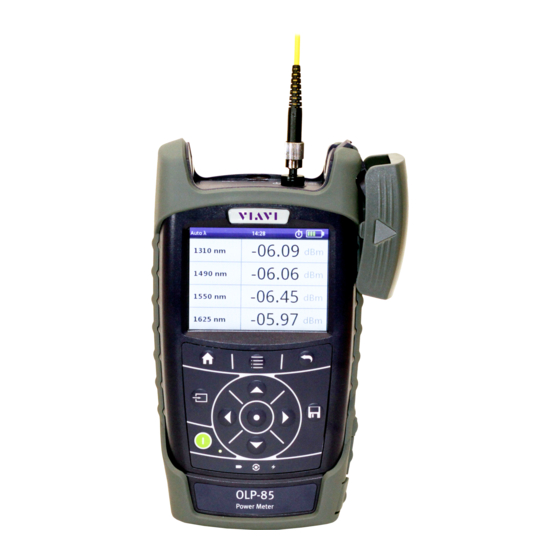
Do not operate the instrument until it has reached its specified temperature range and wait until it has cooled down if the instrument was stored at a high temperature (see “General specifications” on page 82). OLP-85... - Page 14 ETTING TARTED NPACKING THE INSTRUMENT Instrument overview Fig. 3.1 Front view OLP-85 Patch cord microscope (PCM) PCM controls: focus control, automated Pass/Fail analysis, magnification control Connector interface Test head cover 3.5 inch touchscreen Key pad (operator control panel) Battery compartment and stand (on rear of instrument) USB 2.0 device port (Type Micro-B)
- Page 15 USB 2.0 host port (Type A) USB 2.0 device port (Type Micro-B) Power supply The following power sources can be used to operate the OLP-85: • Eight 1.5 V dry batteries (Mignon AA size, alkaline type recommended) • Eight 1.2 V NiMH rechargeable batteries (Mignon AA size, no internal charge) •...
- Page 16 Insert new batteries or remove the used batteries and replace them with fresh ones. NOTICE: Take care to insert the batteries correctly. The correct polarity is indicated by a diagram inside the battery compartment. – or – OLP-85...
- Page 17 • Avoid using this product during electrical storms. There may be a remote risk of electric shock from lightning. • Do not use this product in the vicinity of a gas leak or in any explosive environment. OLP-85...
- Page 18 Centers for disposal. Operation from AC power NOTICE: Only the PS4 Universal AC/DC Power Supply may be used to operate the OLP-85 from AC power. To fit the AC line plug adapter: Select the appropriate AC line plug adapter. Slide the AC line plug adapter into the slot.
-
Page 19: Connecting Optical Cables
Fig. 3.6 PS4: Changing the AC line plug adapter To operate the OLP-85 from AC power: Connect the PS4 DC power cord to the OLP-85 external power supply connector. (The connector is under the cover on the right side.) Plug the PS4 into the AC line socket. -
Page 20: Basic Operation
Glows red when battery is low. Glows red when a measurement is running in the background. Glows orange when battery is charged; flashes orange when battery is charging. Turned off when dry batteries are used or battery bay is empty. OLP-85... -
Page 21: Display Elements
Auto-Off Indicates whether the instrument turns off within a certain time. External power supply The OLP-85 is powered by the external AC adapter when this symbol is shown. Battery status Indicates the battery charge status. If it is not shown, only the AC adapter is active. -
Page 22: Navigating In The Menus
Tap on the display to toggle between the display modes (context-sensitive). Configuring the instrument This chapter describes the configuration of the System Settings. System Settings menu overview √ The homescreen is displayed. ► Press the [A] key and tap the [Settings] button. The System Settings menu opens: OLP-85... - Page 23 Changing the Screen-Off setting Press the [A] key and tap the [Settings] button. Tap the [Screen-Off] button. Select the desired setting to change the screen off time. Notes: Auto-Off and Screen-Off settings are only active when no external power supply is connected. OLP-85...
- Page 24 [Language] button. The language menu opens: Tap the language you want to select. – or – Press the arrow keys to highlight the language you want to select and to confirm press the center key within the arrow keys. OLP-85...
- Page 25 Tap the Ethernet Mode you want to select. Resetting to the factory default values Press the [A] key and tap the [Settings] button. Tap the [Factory Reset] button. Notes: Setting the factory default values does not affect your stored measurement results. OLP-85...
-
Page 26: Software Options
Select a software option from the product line and order it just like an instrument. An e-mail with the license key will be sent. Save the software option to the root of a USB flash drive. Plug the USB flash drive into one of the instrument USB ports. OLP-85... - Page 27 To show the installed software options, tap the [Installed Licenses] button. – or – √ The homescreen is displayed. Press the [A] key and tap the [Software Options] button. To show the installed software options, tap the [View installed licenses] button. OLP-85...
-
Page 28: Probe /Pcm Operation
For best workflow adaption the key action is configurable. The dedicated Magnification Control key provides fast toggling between two microscope magnification levels, low magnification for high level inspection of the fiber endface, and high magnification for detailed inspection of the fiber endface. OLP-85... -
Page 29: Fmae Series Adapters For The Pcm
P5000i provides an exchangable FBPT inspection tip. The dedicated QuickCapture key provides either instant triggering of a pass/fail test or of freezing the live image. For best workflow adaption the key action is configurable. The dedicated Magnification Control key OLP-85... - Page 30 - low magnification for high level inspection of the fiber endface and high magnification for detailed inspection of the fiber endface. The P5000i Digital Probe kit sold with the OLP-85 contains the standard barrel assembly (FBPP-BAP1), standard patch cord tips, and standard bulkhead tips.
-
Page 31: Quickcapture™ Key
To display the live view, tap the [Probe] button. File toolbar Saving a picture It is possible to save the frozen picture from the Digital Probe. Press the [G] key. Edit the file name. Tap the [OK] button. File is saved in the preselected group. OLP-85... -
Page 32: Configuring The Digital Probe
Press the [A] key and tap the [Test] button. – or – Press the QuickCapture™ key on the Digital Probe if the button action is set to Test. When the test procedure terminates, the information shown on the display depends on the current overlay setting: OLP-85... - Page 33 If failed, the frame is red. Fig. 3.11 Pass/Fail analysis – overlay view Magnification Control The Magnification Control allows you to modify the live display from high to low magnification and vice-versa. In the high magnification mode an automatic centering is available. OLP-85...
- Page 34 OLP-85 screen: Click on the [G] key to save a JPG file of the test result in the currently active group on the OLP-85. On the edition keypad, enter the name of the JPG file. Press Enter to validate and save the document.
- Page 35 Select the tip set on the Digital Probe to connect fiber for inspection and tap on the tip set. More Press the [A] key. Tap the [More] button to view or change the storage location, settings and information of the Digital Probe. OLP-85...
-
Page 36: Powermeter Operation
WARNING Dangerous laser radiation Laser radiation can cause irreparable damage to eyes and skin. The maximum permitted power for the OLP-85 means that the optical input signals can reach hazard level. Bear this in mind when using the OLP-85. ►... -
Page 37: Powermeter Measurement
λ To edit the preselected wavelength and set/remove the checkmark, press the center key within the arrow keys. – or – Tap the desired wavelength value. A wavelength is shown or hidden in the preselection. OLP-85... - Page 38 Auto λ, such as a JDSU OLS-85), which can be detected by a JDSU OLP-85 In Auto λ mode the detected wavelength will be included in the λ table. As long as the detected wavelength is active, it cannot be deleted from the λ...
- Page 39 λ Displaying modulated signals automatically detects the modulation frequency of OLP-85 light signals modulated at the fixed frequencies of 270 Hz, 1 kHz and 2 kHz.The detected frequency is shown in the lower right display pane of the Powermeter application.
- Page 40 Tap the desired wavelength value. Press the [A] key. Tap the [Reference] button. The Reference edit mode is displayed. Type in the desired value. Tap the [OK] button. ► For other wavelengths, repeat steps 4 through 7 as required. OLP-85...
-
Page 41: Emory Anagement
EMORY ANAGEMENT General information The OLP-85 allows you to save measured values and inspection images in a structured data memory and recall them as required. Data can also be downloaded via the USB interface to a PC for further evaluation. -
Page 42: Selecting The Group To Save Or Display Results
Digital Probe will be stored in different folders. To save current results successively: √ The instrument is in application mode. Press the [G] key. The Fiber ID edit menu is displayed: Type in the Fiber ID. Tap the [OK] button. The measurement is stored. OLP-85... -
Page 43: Displaying Stored Results
The measurement data of the currently selected group is displayed: To display the last results stored in Probe mode: √ The homescreen is displayed. Tap the [Data] button. Tap the [Probe] button. Measurement data of the currently selected group is displayed. OLP-85... -
Page 44: Generating A Report
Tap the [OK] button. The project is created. To select a project: √ The Data & Reports menu is displayed. Press the [A] key. Tap the [More] button. Tap the [Select Project] button. Select the project you want to link. OLP-85... - Page 45 Press the [A] key. Tap the [Settings] button. Tap the [Linked Applications] button. Tap the [Link Data Mode] button. Tap the [Linked Applications] button. Select the applications you want to link. Press the [F] key to exit from the menu. OLP-85...
-
Page 46: Clearing The Memory
You do not have to clear the entire memory to free up capacity. You can clear individual data or group locations. The OLP-85 has the following memory clear functions: • Delete Selected Clears the data of the selected measurement •... -
Page 47: Maintenance
This cleaning method is very effective and leaves no residue. Blow out the test adapter with clean compressed air (available in spray cans, e.g. anti-dust spray). Notes: Cover the optical connections with the dust cap whenever they are not in use. This prevents them from getting dirty. OLP-85... -
Page 48: Cleaning The Instrument
NOTICE Water and cleaning fluids The instrument may be damaged or destroyed if water or cleaning fluids penetrate it. ► Make sure that water or cleaning fluids do not penetrate the instrument. OLP-85... -
Page 49: Remote Control
The OLP-85 is equipped with a USB 2.0 (Micro-B) device interface for remote control via a PC. In order to operate the OLP-85 via remote control it has to be connected to a PC with a USB cable (see “Accessories” on page 80). - Page 50 Notes: Adding a prefix to a command has the same effect as selecting an application via an application management command. Hence, after using a prefix, the application corresponding to that prefix is the selected application. OLP-85...
- Page 51 9.91E37 (NAN), and most of the Extended Remote Commands will return -100,“Command error”. Query the numerical setting range in the setup The suffixes :MINV and :MAXV return the minimal and maximal allowed values: e.g. :SYSTEM:DISP:BRGH:MINV? returns the value 10 and :SYSTEM:DISP:BRGH:MAXV? the value 100. OLP-85...
-
Page 52: Command Parameters And Responses
If the setting range is used as a response type, 0 and 1 are returned. Examples: 0, OFF, FALSE 1, ON, TRUE <NAN> Not a number. Indicates an invalid result. The returned value is 9.91E37. <STRING> IEEE488.2 <STRING_RESPONSE_DATA> IEEE488.2 OLP-85... -
Page 53: Commands
EMOTE ONTROL OMMANDS Commands Overview Generic commands These commands are always used without a prefix. *IDN? *OPT? *RST :APPM:LIST? :APPM:SEL :APPM:SEL? :APPM:VER? :SYST:DATE :SYST:DATE? :SYST:ERR? :SYST:TIME :SYST:TIME? OLP-85... - Page 54 :INSP:PASS:ZONE:A? ... F? :INSP:ZONE:NUMB? Setups :APP:ID:VSBL :APP:ID:VSBL? :AUTO:CNTR :AUTO:CNTR? :CAPT:BTTN:MODE :CAPT:BTTN:MODE? :FQM:ENAB :FQM:ENAB? :FRZE:BUSY? :INSP:BUSY? :INSP:ERR? :INSP:PRF:NAME :INSP:PRF:NAME? :INSP:PRF:NAMES? :INSP:TBL:SHOW :INSP:TBL:SHOW? :INSP:TIP:NAME :INSP:TIP:NAME? :INSP:TIP:NAMES? :MAGN:HIGH :MAGN:HIGH? :MICR:BAD? :MICR:CON? :MICR:DET? :MICR:OPER:MODE :MICR:OPER:MODE? :OVRL:SHOW :OVRL:SHOW? :STOR:AUTO:INCR:ENAB :STOR:AUTO:INCR:ENAB? :STOR:AUTO:INCR:IDX :STOR:AUTO:INCR:IDX? :STOR:AUTO:INCR:PRFX :STOR:AUTO:INCR:PRFX? :STOR:AVLB? OLP-85...
- Page 55 EMOTE ONTROL OMMANDS :STOR:GRP:NAME :STOR:GRP:NAME? :STOR:GRP:NAMES? :STOR:NAMES? :STOR:NOTE :STOR:NOTE? :STOR:WR:BUSY? Extended commands :APP:FACT:DEF :MICR:CAL:INFO? :MICR:MODL:NAME? :MICR:SER:NUMB? :MICR:SW:VER? :STOR:ALL:DEL :STOR:DEL :STOR:GRP:CREA :STOR:GRP:DEL :STOR:EVAL:TYPE? :STOR:RD? :STOR:RD:EVAL:XML? :STOR:RD:FMAP? :STOR:RD:IMG:HIGH? :STOR:RD:IMG:HIGH:OVRL? :STOR:RD:IMG:LOW? :STOR:RD:IMG:LOW:OVRL? :STOR:WR OLP-85...
- Page 56 1) Only available on instruments with separate optical broadband input. Setups :APP:ID:VSBL :APP:ID:VSBL? :AUTO:LMBD :AUTO:LMBD? :AUTO:LMBD:DTCT? :EVAL:ENAB :EVAL:ENAB? :MEAS:ACT? :SENS:MEAS:MODE :SENS:MEAS:MODE? :SENS:POW:REF :SENS:POW:REF? :SENS:POW:UNIT :SENS:POW:UNIT? :SENS:THRS:PASS :SENS:THRS:PASS? :SENS:WLEN? :SENS:WLEN:TBL :SENS:WLEN:TBL? :SENS:WLEN:TBL:LMT :SENS:WLEN:TBL:LMT? :SENS:WLEN:TBL:REF :SENS:WLEN:TBL:REF? :SENS:WLEN:USER :SENS:WLEN:USER? :STOR:AUTO:INCR:ENAB :STOR:AUTO:INCR:ENAB? :STOR:AUTO:INCR:IDX :STOR:AUTO:INCR:IDX? :STOR:AUTO:INCR:PRFX :STOR:AUTO:INCR:PRFX? :STOR:AVLB? :STOR:GRP:NAME :STOR:GRP:NAME? OLP-85...
- Page 57 EMOTE ONTROL OMMANDS :STOR:GRP:NAMES? :STOR:NAMES? :STOR:NOTE :STOR:NOTE? :STOR:WR:BUSY? 1) Only available on instruments with separate optical broadband input. Extended commands :SENS:ABS:TO:REF :STOR:ALL:DEL :STOR:DEL :STOR:DEL:MLTP :STOR:GRP:CREA :STOR:GRP:DEL :STOR:RD? :STOR:WR OLP-85...
- Page 58 These commands are used with the prefix :SYSTEM. Setups :APP:ID:VSBL :APP:ID:VSBL? :AUTO:OFF :AUTO:OFF? :DISP:BRGH :DISP:BRGH? :DISP:OFF :DISP:OFF? :ETH:MAC:ADDR? :IP:ADDR? :IP:ADDR:STAT :IP:ADDR:STAT? :IP:GATE :IP:GATE:STAT :IP:GATE:STAT? :IP:MASK :IP:MASK:STAT :IP:MASK:STAT? :IP:MODE :IP:MODE? :LANG :LANG? :OPT:INST:BUSY? :OPT:INST:ERR:LIST? :OPT:INST:LIST? :OPT:ULCK? :STOR:AVLB? Extended commands :APP:FACT:DEF OLP-85...
- Page 59 EMOTE ONTROL OMMANDS PowerManagement application These commands are used with the prefix :PMGNT. Results :BATT:CAP:PERC? :BATT:TYPE? :POW:SPLY:CON? Setups :STOR:AVLB? Extended commands :APP:FACT:DEF OLP-85...
- Page 60 Parameter type / Response type / Unit / Info *IDN? Returns the unique identification of the instrument. Response type: <STRING_RESPONSE_DATA> e.g. JDSU Germany GmbH, OLP-85/01,A-0106,V03.30 *OPT? Returns the installed software options. *RST Sets the parameters of all running applications to their default values. Calls :APP:FACT:DEF of all applications.
- Page 61 Response type: <NR1> :INSP:PASS? Pass/Fail result for the complete fiber. Response type: <BOOLEAN> :INSP:PASS Pass/Fail result for fiber zones A–F respectively, depending on the :ZONE:A? ... F? selection. Response type: <BOOLEAN> :INSP:ZONE:NUMB? Number of available inspection zones. Response type: <NR1> OLP-85...
- Page 62 The Digital Probe calculates a focus quality metric for each video frame. <BOOLEAN> If this flag is set to TRUE, the result is displayed as a focus bar on the screen. Deactivating this calculation can speed up video frame rate in some cases. Default: TRUE OLP-85...
- Page 63 Selects one tip out of the tip names map. See :INSP:TIP:NAMES? <STRING> command for more information. Each time the tip names map changes, the tip name has to be updated. :INSP:TIP:NAME? Returns the name of the selected tip. Response type: <STRING> See :INSP:TIP:NAME command for more information. OLP-85...
- Page 64 :MICR:OPER:MODE Selects the operation mode of the Digital Probe. <NR1> Valid values: 0 (Live image) 2 (Snapshot) 3 (Test) Default: :MICR:OPER:MODE? Returns the actual operation mode of the Digital Probe. Response type: <NR1> See :MICR:OPER:MODE command for more information. OLP-85...
- Page 65 See :STOR:AUTO:INCR:PRFX command for more information. :STOR:AVLB? Returns whether the application can or cannot store measurements. :STOR:GRP:NAME Sets the selected storage group name. <STRING> :STOR:GRP:NAME? Returns the name of the currently selected storage group. Response Type: <STRING> See :STOR:GPR:NAME command for more information. OLP-85...
- Page 66 “1.2.41.903”. :STOR:ALL:DEL Deletes all measurement entries and groups. Creates a new empty “default” group. :STOR:GRP:NAME is set to default. :STOR:DEL Deletes a dedicated measurement result specified by group (string1), <STRING>, fiber identifier (string2) and internal identifier (string3). <STRING>, <STRING> OLP-85...
- Page 67 (string2), and internal identifier (string3). <STRING>, Special format: “#h:10091,696e7072cdcc” <STRING> :STOR:RD:IMG Returns the contents of a *.thm.jpg (“thm.jpg” = “test high :HIGH:OVRL? magnification.jpg”) file specified by group (string1), fiber identifier <STRING>, (string2), and internal identifier (string3). <STRING>, Special format: “#h:16100,696e7072cdcc” <STRING> OLP-85...
- Page 68 Response type: <NR1> 0 (PASS) 1 (FAIL) :POW:WATT? Get the measured power level without a level unit. (Level unit is always Watts) :TONE? The detected tone frequency. :WLEN:AUTO? This result contains the result of the Auto λ measurement. OLP-85...
- Page 69 :EVAL:ENAB? Returns the current state of :EVAL:ENAB. :MEAS:ACT? Shows the status of the measurement. Valid results are available if this <BOOLEAN> setup is TRUE. :SENS:MEAS:MODE Selects the measurement mode. <NR1> Valid values: 0 (Absolute) 1 (Relative) 2 (PassFail) Default: OLP-85...
- Page 70 Returns the table of selectable wavelength. See :SENS:WLEN:TBL command for more information. :SENS:WLEN:TBL Is a child map of :SENS:WLEN:TBL containing the threshold limit values :LMT (unit dBm) for all selectable wavelength. Adding or deleting entries in :SENS:WLEN:TBL will automatically update this map. OLP-85...
- Page 71 Valid range: 1 to maximum integer Default: :STOR:AUTO:INCR Returns the current index for the automatic increment feature. :IDX? Response type: <NR1> See :STOR:AUTO:INCR:IDX command for more information. :STOR:AUTO:INCR Sets the prefix for the automatic increment feature. :PRFX <STRING> Default: FIBERID OLP-85...
- Page 72 See :STOR:NOTE command for more information. :STOR:WR:BUSY? Returns TRUE when a measurement is currently stored, otherwise, returns FALSE. Response Type: <BOOLEAN> See :STOR:WR for further information. 1) Only available on instruments with separate optical broadband input. See “Ordering Information” on page OLP-85...
- Page 73 <STRING>, and fiber identifier (string2). If the given group doesn’t exist, it will be <STRING> created. This command creates a dedicated file for each existing wavelength. To create unique file names, this function automatically adds an internal sequence number. OLP-85...
- Page 74 See :AUTO:OFF command for more information. :DISP:BRGH <NR1> Sets the brightness of the display in percent. Valid range: 10 to 100 Default: :DISP:BRGH? Returns the brightness of the display in percent. Response type: <NR1> See :DISP:BRGH command for more information. OLP-85...
- Page 75 In static mode, this setup corresponds to IP:GATE:STAT; in DHCP mode, it is delivered by the DHCP server. This setup is read-only. :IP:GATE:STAT Sets the static mode gateway address. <STRING> :IP:GATE:STAT? Returns the static mode gateway address. Response type: <STRING> See :IP:GATE:STAT command for more information. OLP-85...
- Page 76 1 (de_DE) 2 (fr_FR) 3 (es_ES) 4 (zh_CN) 5 (zh_TW) Default: :LANG? Returns which user interface language is set. Response type: <NR1> See :LANG command for more information. :OPT:INST:BUSY? Returns TRUE if an installation is in progress. Response type: <BOOLEAN> OLP-85...
- Page 77 Returns whether the application can or cannot store measurements. Always FALSE for SYSTEM application. Extended commands for the SYSTEM application Command string Parameter type / Response type / Unit / Info :APP:FACT:DEF Sets all parameters of the application to their default values. OLP-85...
- Page 78 Returns whether the application can or cannot store measurements. Always FALSE for PowerManagement application. Extended commands for the PowerManagement application Command string Parameter type / Response type / Unit / Info :APP:FACT:DEF Sets all parameters of the application to their default values. OLP-85...
-
Page 79: Error Messages
• -108,“Parameter not allowed” • -109,“Missing parameter” • -110,“Command header error” • -112,“Program mnemonic too long” • -113,“Undefined header” • -220,“Parameter error” • -221,“Settings conflict” • -222,“Data out of range” • -224,“Illegal parameter value” • -254,“Media full” • -290,“Memory use error” OLP-85... -
Page 80: Ordering Information
10 O RDERING NFORMATION OLP-85 STAND ALONE UNIT RDERING NFORMATION OLP-85 stand alone unit OLP-85 Power meter, 800–1650 nm, -75 to +26 dBm BN 2307/03 OLP-85P Power meter with integrated patch cord microscope, BN 2308/03 800–1650 nm, -75 to +26 dBm... -
Page 81: Specifications
11 S PECIFICATIONS OLP-85 SPECIFICATIONS PECIFICATIONS OLP-85 specifications Adjustable wavelength range 800 nm to 1700 nm Calibrated wavelenghts 850 nm, 980 nm, 1300 nm, 1310 nm, 1490 nm, 1550 nm, 1625 nm Photo diode filtered InGaAs Fiber types 9/125 to 62.5/125... -
Page 82: General Specifications
2.5 mm UPP (1.25 mm UPP optional) Recommended recalibration 3 years interval Size (H x W x D) OLP-85 208 x 112 x 64 mm (8.2 x 4.4 x 2.5 in) Size (H x W x D) OLP-85P 208 x 153 x 64 mm (8.2 x 6.0 x 2.5 in) - Page 83 Modulated signals 39 Relative 40 Relative power level 40 Power mode 20 Power supply 15 PowerManagement 59, 78 Environmental Management Program Powermeter 56, 68 Measurement 36 Environmental protection 18 Mode 6 Extended commands 78 Probe/PCM 54 Powermeter 73 Project OLP-85...
- Page 84 System 58, 74, 77 Results PowerManagement 78 Powermeter 68 Probe/PCM 61 RoHS 87 Saving results 42 Setups 78 Powermeter 69 Probe/PCM 62 System 74 Shipping damage 13 Specifications General 82 System 57 Test adapter, mounting 19 Update Firmware 26 OLP-85...
- Page 85 Packaging materials Preference is given to reusable or biodegradable single- substance packaging materials whenever possible. Environmental management partnerships JDSU encourages our customers and suppliers who take this responsibility seriously to join JDSU in establishing their own environmental management programs. OLP-85...
- Page 86 The following page provides information with regard to the location of restricted hazardous substances within this equipment according to Chinese requirements. As measuring equipment, this equipment is excluded from the European regulations for the restriction of hazardous substances (RoHS). OLP-85...
- Page 87 RoHS (Additional Information required for the Chinese Market only) RoHS (Component) (Pb) (Hg) (Cd) (PBB) (PBDE) (Main Product) (PCB Assemblies) (Internal wiring) (Display) (Keyboard) (Plastic case parts) (Accessories) SJ/T11363-2006 SJ/T11363-2006 OLP-85...
- Page 88 OLP-85...
Need help?
Do you have a question about the OLP-85 and is the answer not in the manual?
Questions and answers