Table of Contents
Advertisement
Quick Links
Preface
This publication provides the service technician with
information for troubleshooting, testing, and repair of
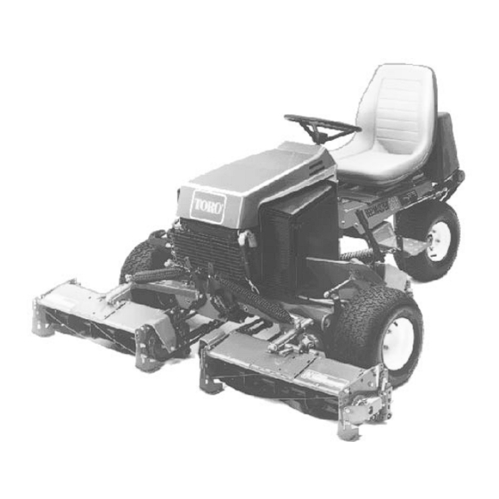
major systems and components on the Reelmaster 216
and Reelmaster 216-D
REFER TO THE REELMASTER 216 OR 216-D
OPERATOR'S MANUAL FOR OPERATING, MAIN-
TENANCE AND ADJUSTMENT INSTRUCTIONS.
Space is provided at the end of Chapter 2 in this publi
cation to insert the Operator's Manuals and Parts
Catalogs for your machine. Replacement Operator's
Manuals are available by sending complete Model and
Serial Number of traction unit and cutting unit to:
The Toro Company
8111 Lyndale Avenue South
Minneapolis, MN 55420
The Toro Company reserves the right to change product
specifications or this publication without notice.
Reelmaster 216
Reelmaster
© The Toro Company - 1991, 1994, 1996
This safety symbol means DANGER, WARN-
ING, or CAUTION, PERSONAL SAFETY IN-
STRUCTION. When you
carefully read the instructions that follow.
Failure to obey the instructions may result in
personal injury.
NOTE: A NOTE will give general information about the
correct operation, maintenance, service, testing or
repair of the machine.
IMPORTANT: The IMPORTANT notice will give im
portant instructions which must be followed to
prevent damage to systems or components on the
machine.
Reelmaster 216-D
Part No. 92783SL, Rev. B
Service Manual
216/216-D
®
see
this symbol,
Advertisement
Chapters
Table of Contents
Troubleshooting

Subscribe to Our Youtube Channel
Related Manuals for Toro Reelmaster 216


Summary of Contents for Toro Reelmaster 216
- Page 1 ® Preface This publication provides the service technician with information for troubleshooting, testing, and repair of major systems and components on the Reelmaster 216 and Reelmaster 216-D This safety symbol means DANGER, WARN- REFER TO THE REELMASTER 216 OR 216-D ING, or CAUTION, PERSONAL SAFETY IN- OPERATOR’S MANUAL FOR OPERATING, MAIN-...
- Page 2 This page is blank.
-
Page 3: Table Of Contents
....6 - 8 (Reelmaster 216) Maintenance Interval Charts....2 - 4 Troubleshooting . - Page 4 This page is blank.
-
Page 5: Chapter 1 - Safety
While Operating......2 Safety Instructions The Reelmaster 216/216-D has been tested and veri fied for compliance with the B71.4-1984 specifications... - Page 6 7. Make sure interlock switches are adjusted correctly 9. Since gasoline and diesel fuel is flammable, handle so engine cannot be started unless traction pedal is in it carefully: NEUTRAL and cutting units are DISENGAGED. A. Use an approved fuel container. 8.
- Page 7 To assure result. optimum performance and continued safety certification of the machine, use genuine Toro replacement parts and 29. Before disconnecting or performing any work on the accessories. Replacement parts and accessories made hydraulic system, all pressure in system must be re...
- Page 8 ® Safety Instructions Page 1 - 4 Reelmaster 216/216-D...
-
Page 9: Product Records
EQUIVALENTS AND CONVERSIONS ..2 Reelmaster 216 ......4 Decimal and Millimeter Equivalents . -
Page 10: Equivalents And Conversions
Equivalents and Conversions Decimal and Millimeter Equivalents ___________________________________________________________________________________________________ Fractions Decimals Fractions Decimals ___________________________________________________________________________________________________ 1/64 0.015625 — 0.397 33/64 0.515625 — 13.097 1/32 ––––– 0.03125 — 0.794 17/32 –––– 0.53125 — 13.494 3/64 0.046875 — 1.191 35/64 0.546875 — 13.891 1/16 –––––––––––– 0.0625 —... -
Page 11: Torque Specifications
Torque Specifications Use these torque values when specific torque values The torque values listed below are for lubricated are not given. DO NOT use these values in place of threads. Plated threads are considered to be lubricated. specified values. Capscrew Markings and Torque Values - U.S. Customary SAE Grade Number ________________________________________________________________________________________________________________________________________________________ Capscrew Head Markings... - Page 12 ® Torque Specifications Page 2 - 4 Rev. B Reelmaster 216/216-D...
- Page 13 Transmission Numbers: ____________________ Date Purchased: ____________________ Warranty Expires __________ Purchased From: ____________________ ____________________ ____________________ Contacts: Parts ____________________ Phone __________________ Service ____________________ Phone __________________ Sales ____________________ Phone __________________ See your TORO Distributor/Dealer for other Publications, Manuals, and Videos from The TORO Company.
- Page 14 ® REELMASTER 216 Maintenance Schedule Minimum Recommended Maintenance Intervals: Maintenance Procedure Maintenance Interval & Service Every Every Every Every 400hrs Check Battery Fluid/Connections Every 200hrs 100hrs 50hrs 25hrs Lubricate Grease Fittings A Level Service Air Filter Pre-Cleaner Service † Change Engine Oil †...
- Page 15 ® REELMASTER 216 Daily Maintenance Check List Unit Designation: __________ Daily Maintenance: (duplicate TORO ID#:_______-_______ this page for routine use) Daily Maintenance Check For Week Of _____________ TUES THURS Maintenance Check Item _______HRS _______HRS _______HRS _______HRS _______HRS _______HRS _______HRS Safety Interlock Operation...
- Page 16 ® REELMASTER 216 Supervisor Maintenance Work Order Date:______________ (duplicate this page for routine use) Unit Designation: TORO I.D. #: Remarks: ____________-____________ Hours: Service to perform (circle): A B C D E Other Technician: -Service (every 25 hours) -Service (every 50 hours)
- Page 17 Transmission Numbers: ____________________ Date Purchased: ____________________ Warranty Expires__________ Purchased From: ____________________ ____________________ ____________________ Contacts: Parts ____________________ Phone __________________ Service ____________________ Phone __________________ Sales ____________________ Phone __________________ See your TORO Distributor/Dealer for other Publications, Manuals, and Videos from The TORO Company.
- Page 18 REELMASTER® 216-D Maintenance Schedule Minimum Recommended Maintenance Intervals: Maintenance Procedure Maintenance Interval & Service Every Every Every Inspect Air Filter, Dust Cup, and Baffle Every 400hrs 200hrs 100hrs 50hrs Lubricate All Grease Fittings † Change Engine Oil A Level Service †...
- Page 19 REELMASTER® 216-D Daily Maintenance Check List Unit Designation:__________ Daily Maintenance: TORO ID#:_______-_______ (duplicate this page for routine use) Daily Maintenance Check For Week Of _____________ TUES THURS Maintenance Check Item _______HRS _______HRS _______HRS _______HRS _______HRS _______HRS _______HRS Safety Interlock Operation...
- Page 20 REELMASTER® 216-D Supervisor Maintenance Work Order Date:______________ (duplicate this page for routine use) Unit Designation: TORO I.D. #: Remarks: ____________-____________ Hours: Service to perform (circle): A B C D Other Technician: -Service (every 50 hours) -Service (every 100 hours) -Service (every 200 hours)
-
Page 21: Specifications
Chapter 3 Kohler Engine Table of Contents SPECIFICATIONS ......1 ADJUSTMENTS ......2 Carburetor Adjustments. - Page 22 Adjustments Carburetor Adjustments Lack of power accompanied by black sooty exhaust 4. Start engine and let it run for 5 to 10 minutes at half smoke is usually caused by a rich carburetor setting. throttle to warm up. Engine must be warm before mak Since a dirty air cleaner element causes the same ing final adjustments.
-
Page 23: Specifications
Chapter 4 Perkins Diesel Engine Table of Contents SPECIFICATIONS ......1 ADJUSTMENTS ......3 GENERAL INFORMATION . -
Page 24: General Information
General Information Bleeding The Fuel System (Fig. 1, 2) CAUTION Because diesel fuel is flammable, use caution when storing or handling it. Do not smoke while filling the fuel tank. Do not fill fuel tank while engine is running, hot or when machine is in an enclosed area. -
Page 25: Adjustments
Adjustments Throttle Linkage Adjustment 1. Adjust low engine speed to 1250 ± 50 RPM at engine. 2. With the engine off, adjust throttle stop on back side of control panel so throttle lever on engine goes against low speed adjustment screw at the same time throttle lever on control panel bottoms out. - Page 26 ® Adjustments Page 4 - 4 Reelmaster 216/216-D...
- Page 27 ..... . . 25 (Reelmaster 216-D) Reelmaster 216 ......6 Traction Pedal Adjustment Reelmaster 216 3WD .
-
Page 28: Specifications
Spin-on cartridge type, 25 micron ________________________________________________________________________________________________________________________________________________________ Hydraulic Oil * Mobil DTE 26 or equivalent ________________________________________________________________________________________________________________________________________________________ Reservoir Reelmaster 216 (Fig. 2) Approximately 3.5 gal. U.S. Reelmaster 216-D (Fig. 3) Approximately 3.3 gal. U.S. * Equivalent Hydraulic Oils GAUGE PORT SYSTEM PRESSURE... -
Page 29: General Information
General Information Hydraulic Hoses Hydraulic hoses are subject to extreme conditions such as, pressure differentials during operation and exposure to weather, sun, chemicals, very warm storage condi CAUTION tions or mishandling during operation or maintenance. These conditions can cause damage or premature de Before disconnecting or performing any work terioration. - Page 30 SAE Straight Thread O-Ring Port - Non-adjustable (Fig. 6) 1. Make sure both threads and sealing surfaces are free of burrs, nicks, scratches, or any foreign material. 2. Always replace the O-ring seal when this type of fitting shows signs of leakage. 3.
- Page 31 Towing (Fig. 9) In case of an emergency, the Reelmaster 216/216-D can be towed for a short distance. However, Toro does not recommend this as a standard procedure. IMPORTANT: Do not tow the machine faster than 2 to 3 MPH because drive system may be damaged.
- Page 32 Hydraulic Schematic (Reelmaster 216) WHEEL MOTOR CONTROL VALVE (RIGHT) BY-PASS VALVE CHARGE CHECK CHARGE CHECK VALVE VALVE PILOT OPERATED VALVE LIFT CYLINDER RESERVOIR CHARGE IMPLEMENT RELIEF RELIEF VALVE VALVE CHARGE PUMP FILTER VARIABLE DISPLACEMENT PUMP COOLER PUMP WHEEL MOTOR (LEFT) ®...
- Page 33 Hydraulic Schematic (Reelmaster 216 3WD) FORWARD WHEEL MOTOR REVERSE (RIGHT) CONTROL VALVE P.C. FLOW CONTROL 1.75 GPM SELECTOR (3WD) BY-PASS VALVE CHARGE CHECK CHARGE CHECK VALVE VALVE PILOT OPERATED VALVE RESERVOIR LIFT CYLINDER IMPLEMENT CHARGE RELIEF RELIEF WHEEL MOTOR VALVE...
- Page 34 Hydraulic Schematic (Reelmaster 216-D) WHEEL MOTOR (RIGHT) CONTROL VALVE VALVE A - TOP VALVE BOTTOM - B BOTTOM BY-PASS VALVE CHARGE CHECK CHARGE CHECK VALVE VALVE B - UPPER A - LOWER BOTTOM FRONT RESERVOIR LIFT CYLINDER CHARGE IMPLEMENT RELIEF...
- Page 35 Hydraulic Schematic (Reelmaster 216-D 3WD) ® Reelmaster 216/216-D Page 5 - 9 Hydraulic Schematic Rev. A (Reelmaster 216-D 3WD)
- Page 36 Special Tools NOTE: Order special tools from the TORO SPECIAL TOOLS AND APPLICATIONS GUIDE (COMMERCIAL PRODUCTS) . Some tools may be listed in the Reelmaster 216 or Reelmaster 216-D Parts Catalog. Some tools may also be available from a local supplier.
- Page 37 You must have o-ring face seal (ORFS) adapter fittings 4. HIGH PRESSURE GAUGE: High range gauge to for this tester to use it on the Reelmaster 216/216-D. accommodate pressure beyond the capacity of the low pressure gauge, 0 - 5000 PSI.
- Page 38 Hydraulic Oil Reservoir Plug (Fig. 13) Used to temporarily plug the outlet of the hydraulic tank to retain most of the fluid when the hydraulic filter is removed. Figure 13 ® Special Tools Page 5 - 12 Reelmaster 216/216-D Rev. A...
- Page 39 Troubleshooting The cause of an improperly functioning hydraulic sys The charts that follow contain detailed information to tem is best diagnosed with the use of proper testing assist in troubleshooting. There may possibly be more equipment and a thorough understanding of the com than one cause for a machine malfunction.
- Page 41 NOTE: Before checking for problems in hydrau lic system, make sure brakes are released. Check for debris in brakes.
- Page 43 Testing The most effective method for isolating problems in the 1. Thoroughly clean the machine before disconnecting hydraulic system is by using hydraulic test equipment or disassembling any hydraulic components. Always such as pressure gauges and flow meters in the circuits keep in mind the need for cleanliness when working on during various operational checks.
- Page 44 Connect tester in series between implement pressure port of hydrostatic pump and pressure inlet port of lift valve (Flow Control Open). Reelmaster 216: Install tester between hose and fitting at front of valve. Reelmaster 216-D: Install tester between hose and fitting at bottom front of pump.
- Page 45 Connect tester in series between traction forward pres sure port of hydrostatic pump and tee connection (Flow Control Open). Reelmaster 216: Install tester between hose coming from bottom front of pump and T-connection on tube line. Reelmaster 216-D: Remove (4) screws securing right fender to frame and remove fender (Fig.
- Page 46 3. Block front of all wheels. 4. Operate engine at full speed: 4. Operate engine at full speed: 3600 ± 100 RPM 3600 ± 100 RPM Reelmaster 216: Reelmaster 216: 3200 ± 100 RPM 3200 ± 100 RPM Reelmaster 216-D: Reelmaster 216-D: 5.
-
Page 47: Reelmaster 216
TEST A: Charge Pressure 1. Make sure hydraulic oil is at operating temperature. 2. Operate engine at full speed: 3600 ± 100 RPM Reelmaster 216: 3200 ± 100 RPM Reelmaster 216-D: 3. Traction pedal and lift valve in neutral. Parking brake engaged. -
Page 48: Test Hook-Up No. 4: Traction Pressure
2. Make sure hydraulic oil is at operating temperature. 3. Operate engine at full speed: 3600 ± 100 RPM Reelmaster 216: 3200 ± 100 RPM Reelmaster 216-D: 4. Attach a heavy chain to rear frame of machine and then to something solid in shop. -
Page 49: Test Hook-Up No. 5: Traction Pressure
Test Hook-up No. 5: Traction Pressure (Fig. 22) (Reelmaster 216-D only) Gauge Connection Connect a 10,000 PSI hydraulic pressure gauge with extension hose to forward traction pressure quick dis connect fitting on hydraulic tube line. TEST A: Traction Pressure 1. Make sure pump drive belt is properly adjusted and in good condition. - Page 50 Adjustments Adjusting Transmission For Neutral (Fig. 23) (Reelmaster 216) If the machine “creeps” when the traction control pedal is in the neutral position, the spring leaf assembly must be adjusted. 1. Block up under the frame so one of the front wheels is off the floor.
- Page 51 Adjusting Transmission For Neutral (Fig. 24, 25) (Reelmaster 216-D) If the machine “creeps” when the traction control pedal is in the neutral position, the spring leaf assembly must be adjusted. 1. Block up under the frame so one of the front wheels is off the floor.
- Page 52 Adjusting Tracton Pedal (Fig. 26, 27) (Reelmaster 216) If traction pedal contacts footrest when pushed fully forward or you cannot get maximum forward traction speed, an adjustment to the traction pedal linkage is required. There should be 3/8 inch clearance between pedal shaft and footrest when pedal is pushed fully forward.
- Page 53 Adjusting Traction Pedal (Fig. 28, 29) (Reelmaster 216-D) If traction pedal contacts footrest when pushed fully forward or you cannot get maximum forward traction speed, an adjustment to the traction pedal linkage is required. There should be 1/16 inch between pedal stop cam and R.H.
- Page 54 Pump Belt Adjustment (Fig. 30) Make sure belts are properly tensioned to assure proper operation ot the machine and unnecessary wear. Check belt midway in span of belt. Check tension again on new belts after 8 hours of operation. Tighten nut on adjustment rod until desired belt tension is attained.
-
Page 55: Repairs
Repairs Removing Hydraulic System Components 1. Thoroughly clean the machine before disconnecting, 3. If a pump was disconnected or removed, prime removing or disassembling any hydraulic components. system before operating. Disconnect fuel stop solenoid Always keep in mind the need for cleanliness when electrical connector on diesel engine or disconnect ig... -
Page 56: Charge Pump
Charge Pump (Fig. 31) 1. Note orientation of charge pump housing to adjacent housing. Scribe a line or make punch marks to assure proper re-installation. 2. Clean the shaft extension to remove all sharp edges, burrs and abrasive residue to prevent shaft seal dam age. -
Page 57: Pump Check Valves
Pump Shaft & Trunnion Seals (Fig. 32) Lip type seals are used throughout the pump. These seals can be replaced without disassembly of the pump; however, replacement of either the input or output seal requires removal of the pump from the machine. 1. -
Page 58: Pump Relief Valves
Pump Relief Valves (Fig. 34) 1. Remove plug ,then slide the spring and poppet out of the housing. IMPORTANT: Do not interchange parts between charge and implement relief valves. Do not alter shims unless adjusting pressure setting of valve. 2. Inspect the poppet and seat in housing for damage and remove any foreign material in the valve area. -
Page 59: Pump Disassembly
Pump Disassembly (Fig. 35, 36, 37, 38) The following procedures are for major repair of the variable displacement pump. These instructions begin with the removal of the end cap. Remove the charge pump, seals, check valves and relief valves before doing major disassembly (See procedures on previous pages of this section). - Page 60 Figure 37 4. Lift out the cylinder block assembly (Item 5). The 5. Visually inspect wear surfaces of valve plate, cylinder pistons may come out of the cylinder block. There is no block and slippers for damage. Check to be sure pistons special orientation of piston to bore that needs to be are free in bores.
- Page 61 Figure 38 7. Place the pump housing (Item 8) with the large cavity bore, the shaft can be removed easily. The swashplate up. Use care not to scratch the port face surface. (Item 37) is then removed from the pump housing. 8.
-
Page 62: Assembly Of Pump
Assembly of Pump (Fig. 39, 40, 41, 42) Figure 39 1. Before assembling, wash parts in solvent. Dry parts 3. Place housing (Item 8) with large cavity up. Use care with compressed air. Do not wipe them dry with a cloth not to scratch the port face surface. - Page 63 Figure 40 6. Install new pins through swashplate and shaft. Use 8. The swashplate should swing freely in the pump two (2) pins in control shaft (Item 28), installing first pin housing to 150° each side of center. until second pin can be started, then driving in both pins together until the last pin is 1/4 inch below swashplate.
- Page 64 Figure 41 9. Lubricate thrust plate (Item 39) with clean hydraulic 12. Slide cylinder block assembly (Item 5) over shaft and oil and insert in counterbore of swashplate. engage spline. Be certain that pistons and thrust plate remain in place. When properly installed a slight spring 10.
- Page 65 Figure 42 14. Properly orient the end cap (Item 45) and housing 18. Install four (4) screws (Item 46) and tighten alter (Item 8). Align the O-rings (Item 44) with the mating nately until the end cap and housing are pulled com holes in the housing.
-
Page 66: Wheel Motor
Wheel Motor (Fig. 43) Figure 43 1. Screw 9. Body & bearing assembly 16. Retainer pin 2. Cover & bearing ass’y 10. Shaft 17. Lip seal 3. Plug 11. Key 19. Thrust washer 4. Seal 12. O-ring 20. Thrust bearing 5. - Page 67 4. Gently slide the oiled seal retainer assembly (Item 15, 3. Insert the shaft (Figure 37, Item 10) and install seals 16, 17) over the shaft, chamfered side first, and press and thrust bearings. (See Assembly of Shaft and Front into the body bore.
-
Page 68: Lift Control Valve
Lift Control Valve (Fig. 44) 1. After removing control valve from machine, wash valve in solvent and dry it thoroughly. 2. Carefully mount control valve into a vise so that control valve mounting pads are against jaws of vise. The control valve spool snap ring (Item 14) should be facing up. - Page 69 Lift Cylinder (Fig. 45, 46, 47) Figure 45 1. After removing cylinder, pump oil out of cylinder into a drain pan by SLOWLY moving cylinder’s piston in and out of cylinder bore. 2. Plug ports and clean the outside of cylinder. Spanner wrench IMPORTANT: To prevent damage when clamping cylinder barrel in a vise, clamp only on pivot end.
- Page 70 5. Grasp end of shaft (Item 4) and use a twisting and pulling motion to carefully extract piston (Item 8), shaft (Item 4), and head (Item 3) from barrel (Item 6). IMPORTANT: Do not clamp vise jaws against shaft surface. Protect shaft surface before mounting in vise.
-
Page 71: 3Wd Selector Valve
3WD Selector Valve (Fig. 48) Figure 48 1. After removing selector valve from machine, wash 8. Inspect all components of control valve assembly for valve in solvent and dry it thoroughly. wear, paying special attention to valve spool. Signs of wear on one side of spool may indicate a bent spool. - Page 72 ® Repairs Page 5 - 46 Reelmaster 216/216-D...
- Page 73 Battery ....... . 25 (S/N 20001 & Up) Reelmaster 216-D ......5 Injection Pump (ETR) Solenoid SPECIAL TOOLS .
-
Page 74: Wiring Schematics
Wiring Schematics Reelmaster 216 (S/N 99999 & Below) ® Wiring Schematics Page 6 - 2 Reelmaster 216/216-D... -
Page 75: Reelmaster 216 (S/N 10001 - 19999)
Reelmaster 216 (S/N 10001 – 19999) ® Reelmaster 216/216-D Page 6 - 3 Wiring Schematics... -
Page 76: Reelmaster 216 (S/N 20001 & Up)
Reelmaster 216 (S/N 20001 & Up) ® Wiring Schematics Page 6 - 4 Reelmaster 216/216-D... -
Page 77: Reelmaster 216-D
Reelmaster 216-D ® Reelmaster 216/216-D Page 6 - 5 Wiring Schematics... -
Page 78: Special Tools
Special Tools NOTE: Order special tools from the TORO SPECIAL TOOLS AND APPLICATIONS GUIDE (COMMERCIAL PRODUCTS) . Some tools may be available from a local supplier. Continuity Tester Battery powered test lamp which is helpful in testing for continuity of circuits and electrical components when the current is off. - Page 79 Skin-Over Grease Special non-conductive grease which forms a light pro tective skin to help waterproof electrical switches and contacts. Figure 3 ® Reelmaster 216/216-D Page 6 - 7 Special Tools...
- Page 80 Troubleshooting (Reelmaster 216) Study the operating characteristics preceding the elec trical failure to help identify the area of difficulty. Try to isolate the failure to a specific functional system; then CAUTION check that area, repairing one component at a time.
- Page 81 Ignition switch wiring loose, cor Repair wiring. roded or damaged. Starter solenoid faulty. Test starter solenoid. Replace if faulty. Starter solenoid wires loose, cor Clean and tighten or repair as roded or damaged. necessary. ® Reelmaster 216/216-D Page 6 - 9 Troubleshooting (Reelmaster 216)
- Page 82 Make sure wires are connected to “COMMON” and “NORMALLY OPEN” (N.O.) terminals. ________________________________________________________________________________________________________________________________________________________ Engine cranks (but should not) Cutting unit clutch switch faulty. Replace switch. with cutting unit clutch switch ON. ® Troubleshooting Page 6 - 10 Reelmaster 216/216-D (Reelmaster 216)
- Page 83 Test alternator and replace if faulty. Dead battery. Charge battery. Replace battery if it will not hold a charge. ________________________________________________________________________________________________________________________________________________________ Battery continuously charges at Regulator / rectifier faulty. Replace regulator / rectifier. high rate. ® Reelmaster 216/216-D Page 6 - 11 Troubleshooting (Reelmaster 216)
- Page 84 OPEN” (N.O.) terminals. Cutting unit interlock switch wiring Repair wiring. faulty. Clutch faulty or out of adjustment. Test clutch. Make sure clutch air gap is properly adjusted.. Clutch wiring faulty. Repair wiring. ® Troubleshooting Page 6 - 12 Reelmaster 216/216-D (Reelmaster 216)
- Page 85 Engine should stop. If engine does not bystanders. Raise cutting units and stop engine. En stop, there is a malfunction in interlock system. Repair gage parking brake. immediately. If engine stops, seat switch is operating correctly. ® Reelmaster 216/216-D Page 6 - 13 Troubleshooting (Reelmaster 216)
-
Page 86: Troubleshooting (Reelmaster 216)
Troubleshooting (Reelmaster 216-D) Study the operating characteristics preceding the elec trical failure to help identify the area of difficulty. Try to isolate the failure to a specific functional system; then CAUTION check that area, repairing one component at a time. -
Page 87: Troubleshooting (Reelmaster 216-D)
Test start relay. Replace if faulty. Start relay wires loose, corroded or Repair wiring. damaged. Starter solenoid wiring loose, cor Repair wiring. roded or damaged. Starter solenoid faulty. Replace starter. ® Reelmaster 216/216-D Page 6 - 15 Troubleshooting (Reelmaster 216-D) - Page 88 Cutting unit clutch switch faulty. Replace cutting unit clutch switch. with cutting unit clutch switch ON. Diode faulty (engine will also crank Replace diode. with traction pedal out of neutral in this situation). ® Troubleshooting Page 6 - 16 Reelmaster 216/216-D (Reelmaster 216-D)
-
Page 89: General Run And Transport Problems
Loose, corroded or damaged Repair wiring. wire(s). Faulty alternator. Check alternator belt tension. Test alternator and replace if faulty. Dead battery. Charge battery. Replace battery if it will not hold a charge. ® Reelmaster 216/216-D Page 6 - 17 Troubleshooting (Reelmaster 216-D) -
Page 90: Cutting Operation Problems
Repair wiring. loose, corroded or damaged. Clutch faulty or out of adjustment. Test clutch. Make sure clutch air gap is properly adjusted.. Clutch wiring loose, corroded or Repair wiring. damaged. ® Troubleshooting Page 6 - 18 Reelmaster 216/216-D (Reelmaster 216-D) -
Page 91: Verify Interlock Operation
Engine should stop. If engine does not bystanders. Raise cutting units and stop engine. En stop, there is a malfunction in interlock system. Repair gage parking brake. immediately. If engine stops, seat switch is operating correctly. ® Reelmaster 216/216-D Page 6 - 19 Troubleshooting (Reelmaster 216-D) -
Page 92: Testing
50 +30 + AC +17 BATTERY 2. RUN B + L & LIGHTS BATTERY 4. GLOW 19 + 30 + AC B + S 3. START & START Figure 5 Figure 4 (Reelmaster 216-D) (Reelmaster 216) ® Testing Page 6 - 20 Reelmaster 216/216-D... -
Page 93: Seat Switch
3. Lower the seat. The continuity tester should show no continuity. Figure 6 NOTE: Make sure the compression spring and pin holds (Reelmaster 216) the seat up off the seat switch when there is no operator on the seat. 1. Seat switch (Item 32) 4. -
Page 94: Traction (Neutral) Switch
Figure 9 there should be continuity across the terminals. With the (Reelmaster 216) cutting units raised and lift cylinder extended there should be no continuity across the terminals. (See Re 1. Cutting unit interlock switch (Item 47) placing the Cutting Unit Interlock Switch in the Repairs section of this chapter for replacement procedures). -
Page 95: Cutting Unit Clutch (Reel Drive) Switch
Cutting Unit Clutch (Reel Drive) Switch (Fig. 11, 12) Reelmaster 216 (S/N 19999 and below) To test switch independent of wiring harness, discon nect wire harness connector(s) from switch terminals. When the switch is ON (Engage), there should be continuity between terminals A – B only. When the switch is OFF (Disengage), terminals C –... -
Page 96: Start And High Temp. Relays (Reelmaster 216-D Only)
Start and High Temp. Relays (Fig. 13, 14, 15) (Reelmaster 216-D only) To test the relay, disconnect the relay wire connector and install a continuity tester between the relay termi nals (terminals 30 and 87). The relay should make and break continuity at terminals 30 and 87 as 12 V.D.C. -
Page 97: Glow Plugs (Reelmaster 216-D Only)
Glow Plugs (Reelmaster 216-D only) Check for continuity between plug terminal and body. If there is no continuity, heat wire in glow plug is broken. Measure resistance between plug terminal and ground. Resistance should be 1.6 ± 0.16 OHM. Resistance of 0 indicates a short circuit. -
Page 98: Injection Pump (Etr) Solenoid (Reelmaster 216-D Only)
Injection Pump (ETR) Solenoid (Fig. 19) (Reelmaster 216-D only) ® The Reelmaster 216-D has an energize-to-run (ETR) fuel stop solenoid mounted on the engine block next to the fuel injection pump with a purple wire attached. The solenoid will stop injector pump fuel delivery with any electrical failure in the RUN circuit. - Page 99 Gauges and Indicator Lights Oil Pressure Light Test the lamp and relay by disconnecting the wire from (Reelmaster 216-D only) high temperature shut-down switch and grounding it Oil pressure lamp should come on when the ignition key against the engine. The light should come on when the...
-
Page 100: High Temperature Shut-Down Switch
High Temperature Shut-Down Switch (Fig. 20, 21) (Reelmaster 216-D only) Switch is located on cylinder head facing front of ma chine with tan wire attached. 1. Lower the coolant level in the engine and remove the high temperature shut-down switch. -
Page 101: Engine Oil Pressure Switch
Engine Oil Pressure Switch (Fig. 20) (Reelmaster 216-D only) Switch is located on cylinder head facing rear of ma chine with brown wire attached. The switch is normally closed (NC) and opens with pressure. Oil pressure switch operating range: 2.8 - 5.7 psi (0.2 - 0.4 kg/cm 1. -
Page 102: Starter Solenoid
12 VDC is connected to the clutch connector terminals. Interlock Module (Reelmaster 216 only) (Fig. 27) The interlock module senses the condition of the seat switch, traction (neutral) switch, and cutting unit clutch (reel engage) switch (Fig. 12). The seat switch must remain CLOSED while the traction switch or cutting unit clutch switch is OPEN or the engine will not run. -
Page 103: Repairs
Battery Service (Fig. 28) Reelmaster 216 IMPORTANT: To prevent damage to electrical com Battery Specifications ponents, do not operate the engine with the battery cables disconnected. -
Page 104: Fuses
Fuses Reelmaster 216 (Fig. 29) The starter circuit is protected by a 30A fuse located on the dash panel. Reelmaster 216 (Fig. 30) The electrical system is protected by a 15A “ACC” fuse located on the dash panel, a 15A “ENGINE” fuse in the wiring harness near the ignition switch and a fusible link in the wiring harness near the starter solenoid. -
Page 105: Traction (Neutral) Switch Replacement
Traction (Neutral) Switch Replacement (Fig. 31) 1. Remove the two wires that are connected to the traction switch. 2. Have a helper push the traction pedal down into either the FORWARD or REVERSE position; this will take the switch arm tension off of the switch. Loosen two (2) screws and remove the switch. -
Page 106: Cutting Unit Interlock Switch Replacement
NOTE: Apply “Loctite 271” or equivalent to threads of Figure 32 switch screws before installing. (Reelmaster 216) 4. Reconnect the two wires to the new switch. Make sure 1. Cutting unit interlock switch (Item 47) that one wire is connected to the “COMMON” terminal, and one wire is connected to the “NORMALLY OPEN”... - Page 107 Brake Service (Reelmaster 216 – S/N 19999 & Below) Parking Brake Adjustment (Reelmaster 216 – S/N 20001 & Up, Reelmaster 216-D) . . 4 (Reelmaster 216 S/N 20001 & Up, Reelmaster 216-D) Steering Column Adjustment....4 Steering Stop Adjustment .
-
Page 108: Specifications
Specifications Item Specification __________________________________________________________________________________________ Tire pressure 12 - 16 PSI ________________________________________________________________________________________________________________________________________________________ Wheel lug nut torque 45 - 65 ft-lb ________________________________________________________________________________________________________________________________________________________ Wheel motor spindle nut torque 250 - 400 ft-lb ® Specifications Page 7 - 2 Reelmaster 216/216-D... -
Page 109: Adjustments
Adjustments Hand Brake Adjustment (Fig. 1) (Reelmaster 216 - S/N 19999 & Below) Brake spacers Figure 1 1. Jack up front of machine and support under frame D. Right brake shoe should have approximately with jack stands. Remove both front wheels. -
Page 110: (Reelmaster 216 S/N 20001 & Up, Reelmaster 216-D)
Hand Brake Adjustment (Fig. 2) (Reelmaster 216, S/N 20001 & Up, Reelmaster 216-D) 1. Jack up front of machine and support under frame with jack stands. Remove both front wheels. 2. Make sure brake is in OFF position. 3. Loosen jam nut on clevis. Remove cotter pin securing of clevis to lower brake lever. -
Page 111: Steering Stop Adjustment
Steering Stop Adjustment (Fig. 4) To increase or decrease turning radius of machine when steering wheel is turned fully left or right, adjust steering stop screws. 1. Loosen locknuts securing stop screws to tabs on steering sector. 2. Thread stop screws in or out until desired turning radius is attained. -
Page 112: Repairs
Repairs Brake Service (Fig. 5) (Reelmaster 216 — S/N 19999 & below) Figure 5 1. Park machine on a level surface. Jack up front of 5. Replace parts that are worn or damaged. machine and support under frame with jack stands. -
Page 113: Brake Service
Brake Service (Fig. 6) (Reelmaster 216 — S/N 20001 & Up, Reelmaster 216-D) Figure 6 1. Park machine on a level surface. Lift front wheel off 6. After installing brake shoes, install brake shoe springs the ground using a jack. Block front and rear of other (Item 17) into holes on each brake shoe plate from the wheels. - Page 114 ® Repairs Page 7 - 8 Reelmaster 216/216-D...
- Page 115 ADJUSTMENTS ......2 Jackshaft and Bearing Service . . . 5 (Reelmaster 216) Cutting Unit Drive Belt Adjustment ... 2 Jackshaft, Bearing and Clutch Adjustment .
-
Page 116: Adjustments
Adjustments Cutting Unit Belt Adjustment Cutting unit drive belts should have a maximum deflec tion of 1/2 in. with 10 lb. load applied to middle of belt span. NOTE: When new belts have been installed, check tension again after the first 8 hours of operation. Old Style Belt Tensioner Assembly (Fig. -
Page 117: Clutch Adjustment (Reelmaster 216)
Clutch Adjustment ) (Fig. 7) (Reelmaster 216 1. Check adjustment by inserting a feeler gauge through slots next to flange studs on clutch (Item 21). 2. Correct disengaged clearance between clutch plates is 0.006 to 0.012 in. It will be necessary to check this... -
Page 118: Repairs
Repairs Clutch Replacement (Fig. 7) (Reelmaster 216) Installing Clutch Removing Clutch 1. Make sure clutch stop (Item 19) is installed in engine block. Clutch stop should extend 0.75 ± 0.03 inch. 1. Loosen tension on jackshaft drive belt (Item 25) and slip belt off of clutch pulley. -
Page 119: Jackshaft And Bearing Service
Jackshaft and Bearing Service ( (Fig. 8) Reelmaster 216) Figure 8 1. Remove tension from cutting unit drive belts and 6. Apply anti-seize compound to keys, then assemble jackshaft drive belt. parts to jackshaft. Do not tighten locking collars (Item 23).Do not tighten pulley setscrews. -
Page 120: Jackshaft, Bearing And Clutch Service (Reelmaster 216)
Jackshaft, Bearing and Clutch Service ) (Fig. 9) (Reelmaster 216-D Figure 9 1. Remove tension from cutting unit drive belts and 6. Inspect bearings (Item 8) and replace if necessary. If jackshaft drive belt. replacing bearing, remove bearing assembly (Item 7) from bearing support (Item 6). - Page 121 10. Align clutch pulley with engine pulley so a straight edge laid across engine pulley face will not have more than a 0.30 in. gap with flanges on clutch pulley, then tighten collars (Item 11) to secure clutch and pulley in Tighten nut against position.
- Page 122 Clutch Service (Fig. 11) (Reelmaster 216) The clutch has a rotor that is driven by the engine crankshaft. When the reel engagement circuit is ener gized, and electromagnet pulls the armature into con tact with the rotor to drive the pulley.
-
Page 123: Clutch Service (Reelmaster 216-D)
NOTE: The air gap is not adjustable on this clutch. The clutch must be serviced in sub-assemblies. Individ ual parts of the clutch can be replaced. See Jackshaft, Bearing and Clutch Service (Reelmaster 216-D) for more information. Figure 12 1. - Page 124 ® Repairs Page 8 - 10 Reelmaster 216/216-D...
- Page 125 Chapter 9 Cutting Units Table of Contents SPECIFICATIONS ......2 SERVICE AND REPAIRS ....12 Front Roller Installation SPECIAL TOOLS .
-
Page 126: Specifications
Specifications Width/Height of Cut: 72 in. (183 cm) width of cut. 5, 8, Height of Cut Adjustment: Positive position settings or 11 blade floating: 1/4 – 1-3/4 in. (6.4 – 44.4 mm); with separate fine adjustments for leveling either end of 5 blade fixed: 1/2 –... -
Page 127: Special Tools
NOTE: Order special tools from the TORO SPECIAL TOOLS AND APPLICATIONS GUIDE (COMMERCIAL PRODUCTS) . Some tools may be listed in the Reel master 216 or Reelmaster 216-D Parts Catalog. Some tools may also be available from a local supplier. Handle Assembly (Fig. 1) -
Page 128: Troubleshooting
Troubleshooting There are a number of factors that can contribute to height may not always be overcome by adjusting the unsatisfactory quality of cut, some of which may be turf machine. It is important to remember that the lower the conditions. - Page 129 Factor Possible Problem/Correction ___________________________________________________________________________________________ 8. Height of cut. All cutting units set at same height of cut. Bench set height of cut and actual (effective) height of cut are different. Effective height of cut depends on cutting unit weight, counterbalance spring adjustment, cut ting unit accessories and turf conditions.
- Page 130 Set Up and Adjustments Adjustment Summary and Check List Monthly Adjustments DETAILED ADJUSTMENT INSTRUCTIONS FOLLOW THIS SUMMARY AND CHECK LIST . Study this informa tion and refer to it often to get maximum life and per NOTE: Remove cutting unit from traction unit. formance from the cutting units.
- Page 131 Cutting Unit Characteristics The single knob bedknife-to-reel adjustment system ing sharp cutting edges, assuring good quality-of-cut, incorporated in this cutting unit simplifies the adjustment and greatly reducing the need for routine backlapping. procedure needed to deliver optimum mowing perform ance.
-
Page 132: Height Of Cut Adjustment And Leveling Rear Roller
Height of Cut Adjustment and Leveling Rear Roller (Fig. 4) (Floating Cutting Units) 1. Position cutting unit on a flat level table or board. 2. Slightly loosen (crack) nut securing each roller bracket to angle bracket. 3. Adjust support capscrew to achieve 1-1/16 in. dimen sion between Height-of-Cut support and front roller bracket (2 places). -
Page 133: Height Of Cut Adjustment And Leveling Rear Roller
Height of Cut Adjustment and Leveling Rear Roller (Fig. 5) (Fixed Cutting Units) 1. Position cutting unit on flat level surface or board. 2. Slightly loosen (crack) nuts securing roller brackets to angle brackets. 3. Adjust support capscrews to achieve 5/8 ± 1/16 in. dimension between Height-of-Cut support and roller bracket (2 places). -
Page 134: Parallel Bedknife To Reel
Parallel Bedknife to Reel (Fig. 6, 7, 8) (Floating or Fixed Cutting Units) 1. Make sure reel contact is removed by turning bed knife adjustment knob counterclockwise. Tip cutting unit to gain access to reel and bedknife. 2. On either end of reel, insert a long strip of dry newspaper between reel and bedknife. -
Page 135: Verifying Height Of Cut Adjustment And Leveling Front Roller
1. On gauge bar, set head of screw to desired Height-of -Cut. This measurement is from bar face to underside of screw head. Gauge bar (Toro Part No. 13-8199) may be obtained from your local Toro Distributor. 2. Slightly loosen (crack) nut securing each front roller bracket to angle bracket. -
Page 136: Service And Repairs
Service and Repairs Front Roller Installation (Fig. 11) (Floating Cutting Units) 1. Remove (2)locknuts securing each angle bracket to cutting unit. 2. Remove height-of-cut pins. 3. Insert smaller diameter. shaft end of roller into white bushing in roller bracket, making sure flanged end of nylon bushing faces inside toward roller. -
Page 137: Installing Cutting Units
Installing Cutting Units (Fig. 12) (Floating Cutting Units) 1. Slide a thrust washer onto lift arm pivot rod. 2. Slide cutting unit carrier frame onto pivot rod and secure with a flat washer, lockwasher and capscrew. Figure 12 1. Thrust washer 2. -
Page 138: Drive Belt And Belt Tensioner Installation
Drive Belt and Belt Tensioner Installation (Fig. 14) (Floating Cutting Units) 1. Route V-belts around jackshaft pulleys and reel pulleys. 2. On pulley end of front cutting units and both ends of rear cutting unit, remove nut from bolt securing carrier frame to tensioner bracket. -
Page 139: Counterbalance Spring Installation
Counterbalance Spring Installation (Figs. 16, 17, 18) 1. Remove capscrew securing counterbalance arm to frame. 2. Remove hairpin cotter and clevis pin next to arm. 3. Pivot front arms outward and rear arm inward. 4. Hook one end of spring into second hole (from bottom) on cutting unit lift tab. -
Page 140: Cutting Unit Overhaul
Cutting Unit Overhaul (Fig. 19, 20) Loctite Anti-seize compound Anti-seize compound Anti-seize compound Torque to 35 ft-lb Anti-seize compound both ends Torque to 200 in-lb Anti-seize compound Figure 19 (8 blade floating cutting unit shown) It is recommended that the following new parts be When assembling cutting unit, apply anti-seize com... - Page 141 When assembling reel (Fig. 19): When assembling S.P.A. handle (Fig. 19): Tighten large jam nut (Item 56) on reel shaft against Tighten locknut (Item 10) so compression spring washer (Item 57) and bearing (Item 30) so that when (Item 11) is 0.86 in. long. capscrew (Item 34) on end of reel shaft is tightened, there will be a 0.060 in.
- Page 142 Connect a lapping machine to the capscrew on the left can result in personal in ury. end of reel shaft with an extension coupler and a 9/16 in. socket. Backlap according to procedures in the Toro Sharpening Reel and Rotary Mowers Manual Form No. 80-300-SL.
- Page 143 This page is blank.
- Page 144 Commercial Products © The Toro Company...
Need help?
Do you have a question about the Reelmaster 216 and is the answer not in the manual?
Questions and answers