
Related Manuals for E+E Elektronik EE240 Series


Summary of Contents for E+E Elektronik EE240 Series
- Page 1 Series EE240 WirElESS SENSOr FOr HUMiDiTY TEMPErATUrE Manual Hardware and Software BA_EE240_04_e // technical data are subject to change // 350118...
- Page 2 EMC disturbances in residential areas. This equipment produces, consumes and can radiate high frequency energy. If not installed and used in accordance with the information in this manual, the EE240 series can cause EMC disturbance.
-
Page 3: Table Of Contents
TABLE OF CONTENTS HARDWARE 1. GENERAL 1.1 Symbol clarification 1.2 Safety instructions 2. PRODUCT DESCRIPTION 2.1 Wireless network 2.1.1 General 2.1.2 Installation of a wireless system 2.1.3 Example for a wireless measurement setup 2.2 Components of the series EE240 2.2.1 Sensing probe 2.2.2 Transmitter 2.2.3 Router 2.2.4 Base station... -
Page 4: General
Symbol Clarification This symbol indicates safety instructions. The safety instructions have to be carried out unconditionally. If disregarded loss, injury, or damage may be inflicted to people and property. In any case E+E Elektronik ® Ges.m.bH. cannot be hold responsible. -
Page 5: Product Description
TRANSMISSION MODULE: Contains FCC ID: MCQ-XBEEPRO2 Contains Model XBee PRO Radio; IC: 1846A-XBEEPRO2 This equipment complies with Part 15 of the FCC Rules. Operation is subject to the following conditions: - this device may not cause harmful interference - under direct influence of EMC interference the device must continue to function, including interference that may cause an undesired operational situation Approval United States... -
Page 6: Installation Of A Wireless System
2.1.2. Installation of a wireless system In principle, in an ideal situation, the transmitter and the router resp. the base station should be within ‘eyesight’ to achieve an optimal strength of the signal. If that is not possible, a more appropriate location can be found using the features of the base station EE242, with the support of an amplifying router. -
Page 7: Router
2.2.3. Router The router is designed to increase the overall transmission distance and to bypass obstacles. Each router has the ability to receive and transmit a maximum of 10 signals (transmitter or another router). It is not possible to connect measuring probes to a router. For a detailed technical description, see chapter 3.3 Router 2.2.4. -
Page 8: Installation
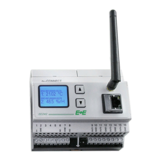
3.1.1. Installation The housing can be installed on DIN-rail. To remove from the rail, both orange snap locks can be opened with the use of a screwdriver. (4.3“) (0.2“) (2.4“) Pluggable antenna which can also be ordered with a remote cable (antenna cable refer to accessories) 3.1.2. -
Page 9: Webserver
3.1.4. Webserver The EE242 can be set up with any desired configuration by means of the webserver; as a result one has full control of the entire network. The base station of the series E240 does not have a data logger. For a detailed technical description, see chapter „Configuration Software“. -
Page 10: Electrical Connections
3.2.2. Electrical Connections Sensing probe All available sensing probes have a matching 4-pin plug, to fit the connector on the transmitter housing. For further detailed information see the data sheet of the particular sensing probe. Transmitter Depending on the type ordered up to three sensing probes can be connected to the transmitter. By means of a pluggable sensor cable (optional) the probe can be installed remotely up to 10m (33ft). -
Page 11: Operating Components
3.2.3. Operating components 3. Display 1. Interval rotary-switch „TIME“ 2. Push-button „CONNECT“ 4. Battery compartment 5. Jumper „J1“ (EXT/BAT) 1. Interval rotary-switch “TIME” With the rotary switch “TIME”, the following transmission and measurement intervals can be selected. Switch position Interval 3 sec. -
Page 12: Router
4. Battery compartment: Alkaline batteries, 4 off (1.5V, AA) 5. Jumper „J1“ (EXT/BAT): The allocation of the jumper allows for the selection of ‘battery power’ or ‘external power’. Router The router is designed to increase the overall transmission distance and to bypass obstacles. Each router has the ability to receive and transmit a maximum of 10 signals (transmitter or another router). -
Page 13: Starting Up The Wireless System
“Point-to-Point” (EE241 with a single transmitter) There is no personal computer necessary to configure the EE241 – the desired setup is configured by E+E Elektronik in accordance with the ordering code. Necessary steps to start up the system: 1) Establish the power supply to the base station. -
Page 14: Calibration Of Measurement System
CALIBRATION OF MEASUREMENT SYSTEM Calibration of the Sensing Probe at E+E’s OEKD-Lab Any of the sensing probes can be sent to E+E’s OEKD-lab for calibration. Customer’s Calibration of the Humidity and Temperature Sensing Probes a) Calibration software on the personal computer: The calibration can be done by means of software on a personal computer =>... -
Page 15: Troubleshooting / Maintenance
TROUBLESHOOTING / MAINTENANCE Replacing Sensing Probes If a sensing probe is damaged (e.g. mechanically damaged,...), the user can replace the probe with a new one without any adjustment of the transmitter. This way an elaborate process of returning the equipment to the factory will be avoided. Procedure to replace a sensing probe: 1) Remove the faulty sensing probe. -
Page 16: Technical Data
TECHNICAL DATA Measuring values of sensing probes Refer to data sheet of respective sensing probes General Transmission frequency 2.4 GHz Transmission system IEEE 802.15.4 Transmission power 10mW Radio range up to 100m indoors, up to 1000m in open field (330 ft) (3300 ft) Antenna pluggable... -
Page 17: Configuration Software
CONFIGURATION SOFTWARE LIMITED LIABILITY E+E Elektronik® is not liable for any direct or consequential damages (for example, but not restricted to loss of earnings, interruption of business, loss of information and data or any other financial losses), which result from the installation, usage and also impossibility of usage of a software product from E+E Elektronik®... - Page 18 In the dialog box “Local Area Connections Properties” point at “Internet Protocol (TCP/IP)” and click the button “Properties”. Check “Use the following IP-address” and change the computer IP-address to 192.168.0.X (choose X between 33 and 63) 192.168.0.64 ist busy with EE242. Enter in the “Subnet Mask”...
-
Page 19: Menu Items
MENU ITEMS 12.1 Overview Shows an overview of the wireless network and its components. Hyperlinks link into the different software menus Status of the entire wireless network “Warn” - warning Warn “Alert” - alarm / failures have occurred Alert “OK” - the entire network functions properly Transmitters: Line 1: number of active transmitters... -
Page 20: Transmitters
12.2 Transmitters Listing of the active routers and transmitters. Transmitter List (chapter 12.2.1) Transmitter Details Probe Details (chapter 12.2.2) Transmitter Status (chapter 12.2.3) 12.2.1 Transmitter List Status: There are three conditions: OK / WARNING / ALERT The following can result in a change of the status: - xxx = Time since the last transmitting (status of wireless connection) - the level of the power supply Data Age:... -
Page 21: Transmitter Details
12.2.2 Probe Status If clicked in the ‘Transmitter List’ on the hyperlink “Name” or “Serial Number”, the details of the selected transmitter will be shown in the bottom part of the screen. Depending on the transmitter model up to three sensing probes can be connected. -
Page 22: Outputs
12.3 Outputs Each analogue output can be configured by clicking on “Edit”: In general there are two methods to map a measurement signal to an analogue output: (a) “mapping the special port ‘X’ of a transmitter ‘Y’ to an analogue output”. This configuration always maps the measurement signal of port ‘X’... -
Page 23: Modbus Map
12.4 Modbus Map Via the link „Add new Modbus Register“, new registers / variables can be created. Register Number: Is incremented automatically, but can be changed any time. Assigned to: Here you select whether a sensor or a transmitter will be mapped to the register. (For details see 12.3. - Page 24 Basic settings Modbus: Main menu -> Management -> Modbus: Basic settings for Modbus-TCP for Modbus-RTU...
-
Page 25: Management
12.5 Management Wireless Network - „Open System”: in this mode the base station is always in “Connect Mode” and can accept at any given time a ‘connection request’ from an E+E transmitter. Attention: if two wireless systems are built parallel to each other a separation of the clients cannot be controlled - “Closed System”: in this mode the base station must be switched to “Connect Mode”... - Page 26 HEAD OFFICE: E+E ELEKTRONIK Ges.m.b.H. Langwiesen 7 A-4209 Engerwitzdorf Austria Tel: +43 7235 605 0 Fax: +43 7235 605 8 info@epluse.com www.epluse.com SALES OFFICES: E+E CHINA / BEIJING Tel: +86 10 84992361 info@epluse.cn www.epluse.cn E+E CHINA / SHANGHAI Tel: +86 21 61176129 info@epluse.cn...
Need help?
Do you have a question about the EE240 Series and is the answer not in the manual?
Questions and answers