
Related Manuals for E+E Elektronik EE741 Series


Summary of Contents for E+E Elektronik EE741 Series
- Page 1 User Manual EE741 Inline Flow Sensor for Compressed Air and Gases BA_EE741 // v1.7 // Modification rights reserved // 194408...
- Page 2 E+E Elektronik Ges.m.b.H. doesn't accept warranty and liability claims neither upon this publication nor in case of improper treatment of the described products. The document may contain technical inaccuracies and typographical errors. The content will be revised on a regular basis. These changes will be implemented in later versions. The described products can be improved and changed at any time without prior notice.
-
Page 3: Table Of Contents
CONTENT General ..............................4 Explanation of Symbols ..........................4 Safety Instructions ............................4 1.2.1 Intended Use ................................4 1.2.2 Mounting, Start-Up and Operation ........................5 Environmental Aspects ..........................5 Scope of Supply ..........................5 Product Description ..........................6 Modular Design .............................7 3.1.1 Changing the Pipe Diameter ..........................7 Functions ...............................8 3.2.1 General ................................8... -
Page 4: General
The user manual may not be used for the purposes of competition without the written consent of E+E Elektronik® and may not be forwarded to third parties. Copies may be made for internal purposes. All information, technical data and diagrams included in these instructions are based on the information available at the time of writing. -
Page 5: Mounting, Start-Up And Operation
Environmental Aspects Products from E+E Elektronik® are developed and manufactured observing of all relevant environmental protection requirements. Please observe local regulations for the device disposal. For disposal, the individual components of the device must be separated according to local recycling regulations. -
Page 6: Product Description
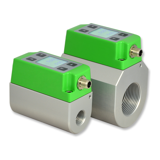
Product Description The EE741 flow sensor operates on the thermal mass flow measurement principle and is suitable for measuring the flow of compressed air and gases in pipelines. It can be used for measuring the consumption of compressed air, nitrogen, argon, oxygen, CO or other non-corrosive and non-flammable gases. -
Page 7: Modular Design
Modular Design One and the same sensing unit can be used for each of three pipe diameters: EE741: DN15 / DN20 / DN25 (1/2") (3/4") (1") EE741-N50: DN32 / DN40 / DN50 (1-1/4") (1-1/2") (2") The pipe diameter is easily changed via the display menu or the EE-PCS Product Configurator Software (available for free download at www.epluse.com/... -
Page 8: Functions
Functions 3.2.1 General Maximum consumption value on the display The consumption value on the display is limited at 999 999 999.0 m . For value above this, the display shows “LCD maximum”, while internally the consumption is metered normally up the maximum value of 3.4 * 10 . -
Page 9: Digital Interface
The minimum time between two pulses is 2 s. OUT 2 ≥ 2 s min. 2/3 Fig. 5 Pulse-pause ratio The pulse duration and the pulse value can be calculated with following MIN/MAX-Formula: Calculating the min. “pulse value” or the max. “pulse duration”: IMPW_MIN = NORMV_MAX [m³/h] * IMPL [s] / 1200 IMPL_MAX = IMPW [m³] * 1200 / NORMV_MAX [m³/h] IMPW... -
Page 10: Mechanical Installation
Mechanical Installation Installation Dimensions 4.1.1 Installation Dimensions Gauge Mounting Block EE741: Internal thread: Whitworth thread according to EN 10226 (old DIN 2999) or NPT Gauge Thread mounting EE741-N50: or NPT block DN15 1/2" DN20 3/4" DN25 1" DN32 1-1/4ʺ DN40 1-1/2ʺ... -
Page 11: Choosing The Appropriate Mounting Location
Choosing the Appropriate Mounting Location • The mounting location site shall be easily accessible and free of vibration. • A minimum clearance of 150 mm (5.9") shall be observed around the mounting location for installing / removing the sensing unit of the EE741. •... -
Page 12: Inlet And Outlet Measurement Path
Flow Direction Horizontal mounting, sensing unit horizontal Horizontal mounting, sensing unit at bottom F l o w D i r e c t i o n + ... Recommended installation position - ..Not recommended Inlet and Outlet Measurement Path For measurement accuracy according to product specification, the EE741 flow sensor shall be located as far as possible from flow disturbances caused for instance by pipe reductions or expansions, bends, T-pieces, valves or sliders. -
Page 13: Installation Of The Gauge Mounting Block
Installation of the Gauge Mounting Block 4.5.1 Gauge Mounting Block The gauge mounting block is symmetrical and can be installed in the pipeline irrespective of the flow direction. • All connections must be properly sealed and checked for tightness. • The thread seals shall not impact on the cross section of the pipe or of the block. 4.5.2 Gauge Mounting Block with Flanges The gauge mounting block with flanges is symmetrical and can be installed in the pipeline... -
Page 14: Mounting The Sensing Unit Unit Into The Gauge Mounting Block
Mounting the Sensing unit Unit into the Gauge Mounting Block Depressurize the pipeline before mounting or removing the sensing unit unit. In case the gauge mounting block has been operated without sensing unit, remove the sealing plug with a WAF 13 spanner. Remove the protective cap from the sensing head (Fig. -
Page 15: Electrical Installation
Electrical Installation The electrical installation of the EE741 shall be performed by qualified staff only. Observe all applicable national and international requirements for the installation of electrical devices as well as power supply according to EN 50178, SELV, PEL. Connection Diagram M12 4 pole connector according to IEC 61076-2-101 Fig. -
Page 16: Digital Interface
Digital Interface 5.2.1 M-Bus (Meter Bus) The M-Bus (Meter Bus) is a field bus for recording consumption data. Transmission runs serially on a reverse polarity protected two-wire line. The EE741 flow sensor as M-Bus slave requires a separate supply voltage. There is no prescribed specific topology (line or star) for the wiring. Normal phone cable of type J-Y(St)Y Nx2x0.8 mm can be used. -
Page 17: Modbus Rtu
5.2.2 Modbus RTU EE741 flow sensor can be operated in a Modbus RTU network with max. 32 devices. Writing 0 into the corresponding register will reset the MIN/MAX values and the consumption meter. For Modbus protocol settings see Application Note Modbus AN0103 (www.epluse.com/EE741). Modbus Map: Register number Register address... - Page 18 The recommended baud rate for several devices in the Modbus RTU network is 9600. Device address, baud rate, parity and stop bits can be set via: 1. EE-PCS, Product Configuration Software and USB configuration interface (see chapter 5.3). The EE-PCS can be downloaded free of charge from www.epluse.com/configurator 2.
-
Page 19: Io-Link
5.2.3 IO-Link Communication specification Manufacturer ID 0563 / 1379 Device IDs EE741 DN15 to DN25 : 0x074111 475409 d EE741 DN15 to DN25: EE741 DN32 to DN50 : 0x074112 475409 d EE741 DN32 to DN50: Bitrate COM2 (38.4 kBaud) Minimum cycle time 6.0 ms SIO mode supported Process data input length... -
Page 20: Usb Configuration Interface
USB Configuration Interface The micro USB port is located behind a blind cover (Fig. 15 and Fig. 16) Blind coupling USB cable Fig. 15 Remove the blind cover Fig. 16 Plug in the USB cable For EE741 setup and configuration via USB interface it is necessary to install the EE-PCS Product Configuration Software on a personal computer. -
Page 21: Measured Value Display
Measured Value Display Upon power on the display is in measuring mode and shows the measured values. One can select among six measurands and a status page (Fig. 19 and Fig. 20). Abbreviations for measurands: T ... Temperature V'n ... Standard volume flow m' ... - Page 22 Measuring mode Setup mode Output 1 Output 2 Pipe diameter Status DNxx Measurand 1 Display Measurand 2 Process param. Low-flow cut-off Measurand 3 Counter reading Measurand 4 Min/Max Measurand 5 Settings Measurand 6 Fig. 21 Display - menu guidance Output 1 Configuration for output 1: analogue or switch output, measurand, scale and switch setup.
-
Page 23: Error Messages
Error Messages Error messages are available on the status page of the display and at the status LEDs. Green LED Red LED Fig. 22 Status LED - error message 0: no error / green LED flashes 1: EEPROM faulty / green LED flashes, red LED lights up Cause: The EEprom for storing the consumption meter status and the MIN/MAX values is faulty. -
Page 24: Removing The Sensing Unit From The Gauge Mounting Block
Removing the Sensing Unit from the Gauge Mounting Block Depressurize the pipeline before mounting or removing the sensing unit unit. Ensure that the line is depressurized and release the mounting screws of the sensing unit (Fig. 23 and Fig. 24). Fig. -
Page 25: 10 Technical Data
10 Technical Data Measurands Flow Standard conditions 1 013.25 mbar , 0 °C (configurable) (factory setting) (14.7 psi) (32 °F) Measurement range 1) in air DN15 (1/2"): 0.2...76.3 Nm (0.12...44.88 SCFM) DN20 (3/4"): 0.4...135.7 Nm (0.24...79.77 SCFM) DN25 (1"): 0.6...212 Nm (0.36...124.71 SCFM) DN32 (1-1/4"): 0.9...347.4 Nm (0.52...202.06 SCFM) -
Page 26: 10.1 Factory Settings Of The Outputs For Dn15 / Dn20 / Dn25
10.1 Factory Settings of the Outputs for DN15 / DN20 / DN25 Analogue output Switch output Minimum flow hysteresis mode shutdown Pipe from diameter Standard volume flow [Nm³/h] DN15 0.15 0.07 DN20 0.25 0.12 DN25 0.35 0.17 Standard volume flow [Nm³/min] DN15 1.25 0.83... -
Page 27: 10.2 Factory Settings Of The Outputs Dn32 / Dn40 / Dn52
10.2 Factory settings of the outputs DN32 / DN40 / DN52 Analogue output Switch output Minimum flow hysteresis mode shutdown Pipe diameter from Standard volume flow [Nm³/h] DN32 0.55 0.25 DN40 0.45 DN50 Standard volume flow [Nm³/min] DN32 DN40 0.58 DN50 13.3 Standard volume flow [l/min]... -
Page 28: 10.3 Works Certificate
Es wird bestätigt, dass die Lieferung den Vereinbarungen bei der Bestellung entspricht. We hereby certify that the material described above complies with the terms of the order. Geprüft / Supervised E+E Elektronik Ges.m.b.H. Tel.: +43 7235 605-0 Langwiesen 7 Fax. +43 7235 605-8... - Page 29 HEADQUARTERS SUBSIDIARIES E+E Elektronik Ges.m.b.H. E+E Elektronik China E+E Elektronik Germany E+E Elektronik Korea Langwiesen 7 18F, Kaidi Financial Building, Schöne Aussicht 8 C Suite 2001, Heungdeok IT 4209 Engerwitzdorf No.1088 XiangYin Road 61348 Bad Homburg Valley Towerdong, 13, Austria 200433 Shanghai Tel.:...
Need help?
Do you have a question about the EE741 Series and is the answer not in the manual?
Questions and answers