
Related Manuals for E+E Elektronik EE240


Summary of Contents for E+E Elektronik EE240
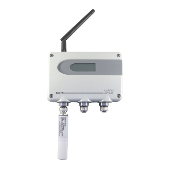
- Page 1 OPERATING MANUAL Series EE240 Wireless Sensor for Humidity Temperature BA_EE240_e // V8.0 // technical data are subject to change // 350118...
- Page 2 E+E Elektronik Ges.m.b.H. accept warranty and liability claims neither upon this publication nor in case of improper treatment of the described products. The document may contain technical inaccuracies and typographical errors. The content will be revised and updated on aregular basis. The described products can be improved and changed at any time without prior notice.
-
Page 3: Table Of Contents
STARTING UP THE WIRELESS SYSTEM ......................14 Necessary Steps to Start up the System .....................14 Increasing the Transmission Distance with Routers ..................15 Parallel Operation of Several EE240 Wireless Networks ................15 CALIBRATION OF MEASUREMENT SYSTEM ....................16 Calibration of the EE244 Sensing Probes at E+E’s OEKD-Lab ..............16 Customer’s Calibration of the Humidity/Temperature Sensing Probes ............16... -
Page 4: General
The operation manual may not be used for the purposes of competition without the written consent of E+E Elektronik® and may not be forwarded to third parties. Copies may be made for internal purposes. All information, technical data and diagrams included in these instructions are based on the information available at the time of writing. -
Page 5: Product Description
2.1.1 General The series EE240, based on the “ZigBee” protocol, transmits at a frequency of 2.4 GHz with a power of 6,3 mW. A bi-directional wireless connection prevents loss of data, if disturbances may occur. The maximum transmission distance depends greatly on the local conditions. Obstacles, like walls of reinforced concrete, steel buildings, or structures attenuate the signal and decreases the transmission distance. -
Page 6: Installation Of A Wireless System
Transmitter The transmitter powers the sensing probe and transmits wirelessly the measurement data. Each trans- mitter can be equipped with a maximum of three sensing probes. For a detailed technical description, see chapter 3.2. Operating manual Series EE240 Wireless sensor... -
Page 7: Router
(antenna cable refer to accessories) 3.1.2 Electrical Connections Screw terminal assignment of series EE242: Jumper to enable the Modbus termination resistor RS485 24V AC/DC* Modbus RTU SELV *) The supply circuit must be fused with ≤ 8A Operating manual Series EE240 Wireless sensor... -
Page 8: Operating Components
To reset the system to the default factory settings, the push-button “Connect” should be pressed for 10 seconds. All wireless connections (with transmitters and routers) will be cancelled. All settings will reset to the default factory settings: IP address of the base station, password of the web server, etc. Operating manual Series EE240 Wireless sensor... -
Page 9: Transmitter, Sensing Probe
2. Mount the bottom part of the housing with 4 screws; less than 4.2mm in diameter (not in the scope of supply). 3. Connect the transmitter (see chapter 3.2.2 Electrical Connections). 4. Install the cover with 4 screws (in the scope of supply). Operating manual Series EE240 Wireless sensor... -
Page 10: Electrical Connections Ee244
• After successful launch of the transmitter close the cover carefully. Attention: Please do not dispose of old equipment and used batteries in domestic waste. Take them to the environmentally compliant disposal at designated collection points in accordance with national or local regulations. Operating manual Series EE240 Wireless sensor... -
Page 11: Operating Components Ee244
Warning: The measured values are updated in the adjusted interval „TIME“ (see chapter 3.2.3.1). 4. Battery compartment: Alkaline batteries, 4 off (1.5V, AA) 5. Jumper „J1“ (EXT/BAT): The allocation of the jumper allows for the selection of ‘battery power’ or ‘external power’. Operating manual Series EE240 Wireless sensor... -
Page 12: Installation Ee245
Mounting holes 32 (1.3“) 31 (1.2“) 85 (3.3“) 11,5 (0.5“) 3.2.5 Electrical Connections EE245 - for external supply 10 9 power supply DC 8-28V SELV AC 12V (±20%) See page 10 for battery replacement. Operating manual Series EE240 Wireless sensor... -
Page 13: Operating Components Ee245
"signal strength level [%] of the wirless connection for 60 sec before switching back to the normal display mode. 3. Jumper „J1“ (EXT/BAT): The allocation of the jumper allows for the selection of ‘battery power’ or ‘external power’. 4. Battery compartment: Alkaline batteries, 4 off (1.5V, AA) Operating manual Series EE240 Wireless sensor... -
Page 14: Router
- PC with admin authotization, no disk space is needed on the personal computer, because the EE242 is equipped with a web server. - crossover cable (PC-EE242: HA010333) for connecting directly with the EE242 or Switch and two network cables. Operating manual Series EE240 Wireless sensor... -
Page 15: Increasing The Transmission Distance With Routers
Each wireless network is built around an EE242 base station, and depending on the number of trans- mitters, may include one or more EE244-R routers. For the parallel operation of several EE240 net- works at one site it is of paramount importance for each transmitter and router to be within the transmission range of the routers and basis station of only one network. -
Page 16: Calibration Of Measurement System
(type EE07). E+E’s “Humor 20” can be utilized as the high accurate humidity calibrator (see chapter 8. Replacement Parts / Accessories). T probe RH probe Operating manual Series EE240 Wireless sensor... -
Page 17: Troubleshooting / Maintenance
• New erected obstacles (metal structures …) attenuate the wireless signal → Bypass the obstacles utilizing additional router(s). Forgot password • → Reset the base station E242 to the default factory settings (IP- address, Password,.) see chapter 3.1.5. Network Reset. Operating manual Series EE240 Wireless sensor... -
Page 18: Technical Data
2.5mm Housing material polycarbonate (PC) Protection class housing IP20 Temperature ranges working temperature: -30...50°C (-22...122°F) (with display: -20...50°C / -4...122°F) storage temperature: -30...50°C (-22...122°F) (with display: -20...50°C / -4...122°F) 1) with external supply Operating manual Series EE240 Wireless sensor... -
Page 19: Replacement Parts / Accessories
CONFIGURATION SOFTWARE Limited Liability E+E Elektronik® is not liable for any direct or consequential damages (for example, but not restricted to loss of earnings, interruption of business, loss of information and data or any other financial losses), which result from the installation, usage and also impossibility of usage of a software product from E+E Elektronik®... -
Page 20: Creating An Ethernet Connection Between Personal Computer And Ee242
(choose X between 33 and 63). Properties” point at “Internet Protocol (TCP/IP)” and click the button “Properties”. 192.168.0.64 is already used by EE242! Enter in the “Subnet Mask” field ‘255.255.255.0’ and click the “OK” button to save the setup. Operating manual Series EE240 Wireless sensor... -
Page 21: Menu Items
Base Station: Line 1: model number Line 2: serial number of the base station Line 3: elapsed time since last interruption Webserver: All indicated data are updated in a 5sec-interval. Operating manual Series EE240 Wireless sensor... -
Page 22: Transmitters
Components, under 1. Interval rotary switch “TIME”) or direct from the web server. The change to the new selected transmission interval will take place at the next interval, and until that moment shown between brackets. For example: current interval = 30 sec, new interval = 10 min. Operating manual Series EE240 Wireless sensor... -
Page 23: Probe Status
If a sensing probe has to be replaced (e.g. calibration, etc...), this can be done in a few easy steps: 1. Disconnect the old sensing probe. 2. Connected the new sensing probe. 3. Remove the old sensing probe from the system by clicking “Delete Probe”. Operating manual Series EE240 Wireless sensor... -
Page 24: Transmitter Status
Transmitter Port: Select the transmitter port (see chapter 12.2.2 Transmitter Details, under “TM-Port”) to which the sensing probe is connected (Port 1, 2 or 3, resp.” 255”, if only one port is occupied, but the port number is unknown). Operating manual Series EE240 Wireless sensor... -
Page 25: Modbus Map
Possible multiplication factor for the register value (Reg.Value = Current Value * Factor) Offset: Possible offset for the register value (Reg.Value = Current Value * Factor + Offset) Create Register: The register will be created with the selcted configuration. Operating manual Series EE240 Wireless sensor... - Page 26 Using "Edit", the configuration of each register can be changed. (in the list „Modbus Register Map“) Via the button „Delete Register“ the selected register will be deleted. Basic settings Modbus: Main menu ► Management ► Modbus: Basic settings for Modbus-TCP for Modbus-RTU Operating manual Series EE240 Wireless sensor...
-
Page 27: Management
This feature allows to save all settings to a Backup-File on the PC to restore the old settings in case of an accidental reset to "factory settings" (see section 3.1.5). Passwords Here the login-designation (admin, reader) and the password can be changed. 12.6 About Operating manual Series EE240 Wireless sensor... - Page 28 HEADQUARTERS SUBSIDIARIES E+E Elektronik Korea E+E Elektronik Ges.m.b.H. E+E Elektronik Germany E+E Elektronik France Tel: +82 31 732 6050 Langwiesen 7 info@epluse.de info@epluse.fr info@epluse.co.kr A-4209 Engerwitzdorf Tel: +33 4 74 72 35 82 Office Bad Homburg Austria E+E Elektronik China...
Need help?
Do you have a question about the EE240 and is the answer not in the manual?
Questions and answers