
Subscribe to Our Youtube Channel
Related Manuals for E+E Elektronik EE850


Summary of Contents for E+E Elektronik EE850
- Page 1 User Manual EE850 Duct Sensor for , Humidity and Temperature BA_EE850 // v1.5 // Modification rights reserved...
- Page 2 E+E Elektronik Ges.m.b.H. does not accept warranty and liability claims neither upon this publication nor in case of improper treatment of the described products. The document may contain technical inaccuracies and typographical errors. The content will be revised on a regular basis.
-
Page 3: Table Of Contents
Installation ..............................6 Electrical Connection .............................7 Setup and Adjustment ...........................7 Digital Settings ..............................9 3.5.1 Bus Termination Resistor .............................9 3.5.2 Address Setting ..............................9 3.5.3 BACnet Setup ..............................9 3.5.4 Modbus Setup ..............................10 Modbus RTU Example ..........................11 Technical Data ...........................12 User Manual EE850 Duct Sensor... -
Page 4: General
(dv), mixing ratio (r), water vapour partial pressure (e) or enthalpy (h). The use of the EE850 in any other way than described in this manual bears a safety risk for people and the entire measurement installation and is therefore not allowed. -
Page 5: Installation, Start-Up And Operation
1.2.3 Installation, Start-up and Operation The EE850 duct sensor has been designed and produced under state of the art manufacturing conditions, has been thoroughly tested and has left the factory after fulfilling all safety criteria. The manufacturer has taken all actions to assure safe operation. The user has to make sure that the equipment is positioned and installed in such a way that safe operation is not impaired. -
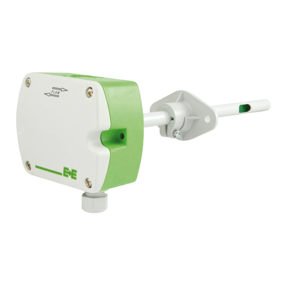
Page 6: Product Description
CABLE GLAND M16x1,5 EE850 with conduit connection for the North American market: use a flat screwdriver to carefully break open the plastic knockout at the marked location, in order to avoid damaging the electronics inside the enclosure. The conduit adapter is not included in the scope of supply. -
Page 7: Electrical Connection
RS485 EE850-M1xJ3 Setup and Adjustment The EE850 is ready to use and does not require any configuration by the user. The factory setup of EE850 corresponds to the type number ordered. For ordering guide please see data sheet at www.epluse.com/EE850. - Page 8 ƒ After changing the factory setup (output signal and/or output scale) the original type number on the EE850 identification label loses its validity; it does not match any longer the device setup. ƒ The return to factory setup function of EE-PCS restores the original adjustment/calibration of the device, but does not affect the user setup for output signal and output scale.
-
Page 9: Digital Settings
(see technical data) at any time and at all devices in the bus. This is particularly relevant when using long and thin cables which can cause high voltage drop. Please note that a single EE850 requires peak current of 350 mA. -
Page 10: Modbus Setup
Digital interface default settings The recommended settings for multiple devices in a Modbus RTU network are 9600, 8, even, 1. The EE850 represents 1/10 unit load on an RS485 network. Device address, baud rate, parity and stop bits can be set via: 1. -
Page 11: Modbus Rtu Example
1) Register number starts from 1. 2) Protocol address starts from 0. If the ID is set via DIP switch the response will be NAK. 4) For Modbus protocol settings see Application Note Modbus AN0103 (available on www.epluse.com/EE850). INFO (read register) Parameter... -
Page 12: Technical Data
-1 mA < I < 1 mA RH scale: 0...100 % RH Digital Interface RS485 EE850 = 1/10 unit load Protocol Modbus RTU or BACnet MS/TP Passive temperature, 2-wire T sensor type according ordering guide Wire resistance (terminal - sensor), typ. - Page 13 HEADQUARTERS SUBSIDIARIES E+E Elektronik Ges.m.b.H. E+E Elektronik China E+E Elektronik Germany E+E Elektronik Korea Langwiesen 7 18F, Kaidi Financial Building, Schöne Aussicht 8 C Suite 2001, Heungdeok IT 4209 Engerwitzdorf No.1088 XiangYin Road 61348 Bad Homburg Valley Towerdong, 13, Austria 200433 Shanghai Tel.:...
Need help?
Do you have a question about the EE850 and is the answer not in the manual?
Questions and answers