Advertisement
Quick Links
QUICK GUIDE
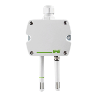
EE211 - Humidity and Temperature Sensor for Continuous High Humidity
(Full User Guide at www.epluse.com/EE211)
Assembly and Installation
•
Insert the M20 cable gland included in the scope of supply into the corresponding opening of the EE211 basis unit and fix it tight
with the nut.
•
Install the EE07-MT temperature probe either directly onto the M12 connector of the EE211 basis unit or using the optional
probe cable.
Connection Diagram
EE211-M1J3 - Digital Output
Address switches
EE211-M1A2/3/5/6 - Analogue Output
Analogue Settings
Selection Output Signal Voltage / Current
The factory setup of the output signal and scaling corresponds to the type number as ordered.
The output signal voltage (U) or current 3-wire (I) can be selected with the DIP switch on the main electronics board (see
Connection Diagram - EE211-M1A2/3/5/6). This does not impact on the scaling of the outputs, which can be changed using the
EE-PCS Product Configuration Software and the optional USB configuration adapter HA011066.
Digital Settings - RS485 Interface with Modbus RTU Protocol
Hardware Bus Termination
If required, the bus termination shall be realized with 120 Ohm resistor, jumper on the board.
Jumper mounted
= bus terminated
Jumper not mounted
= bus not terminated
Address setting via EE-PCS Product Configuration Software
All DIP switches at position 0 → address has to be set via
Product Configuration Software
Factory setting: 239 (permitted values: 1...247).
Example: Slave address is set via configuration software.
Address Switch:
0 0 0 0 0 0 0 0
Digital Settings
Factory settings
Baud rate
9600
Data bits
8
Parity
EVEN
Stop bits
1
Slave address
239
For details how to set the ID address, baud rate, parity and stop bits, please see Full User Guide at www.epluse.com/EE211.
15...35 V DC
24 V AC ± 20%
Bus termination resistor 120 Ω (jumper)
15...35 V DC
24 V AC ± 20%
Selection output signal U / I
0
1
9600, 19200, 38400, 57600, 76800, 115200
8
None, odd, even
1 or 2
1...247
Output:
Modbus RTU
V
V
Output: 0...5 V
mA
mA
0...10 V
0...20 mA
4...20 mA
Address setting via DIP switch
Setting the DIP switches to any other address than 0,
overrules the slave address set via configuration software
(permitted values: 1...247).
Example: Slave address set to 11 (= 0000 1011 binary).
Address Switch:
Selectable values
OUT1
OUT2
Setup interface
0
1
1 1 0 1 0 0 0 0
Advertisement

Subscribe to Our Youtube Channel
Related Manuals for E+E Elektronik EE211


Summary of Contents for E+E Elektronik EE211
- Page 1 (Full User Guide at www.epluse.com/EE211) Assembly and Installation • Insert the M20 cable gland included in the scope of supply into the corresponding opening of the EE211 basis unit and fix it tight with the nut. • Install the EE07-MT temperature probe either directly onto the M12 connector of the EE211 basis unit or using the optional probe cable.
- Page 2 2) Register address starts from 0 3) The choice of measurement units (metric or non-metric) must be done in the ordering guide, see EE211 data sheet. Switching from metric to non-metric or vice versa by using the EE-PCS is not possible.
Need help?
Do you have a question about the EE211 and is the answer not in the manual?
Questions and answers