E+E Elektronik EE600 Operation Manual
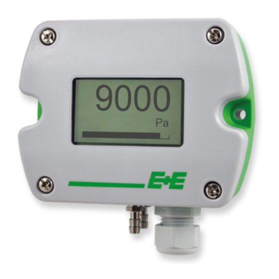
Differential pressure sensor
Hide thumbs
Also See for EE600:
- User manual (30 pages) ,
- Quick manual (2 pages) ,
- User manual (22 pages)

Subscribe to Our Youtube Channel
Related Manuals for E+E Elektronik EE600


Summary of Contents for E+E Elektronik EE600
- Page 1 Operation Manual EE600 Differential Pressure Sensor BA_EE600_e // v1.1 // technical data are subject to change...
- Page 2 E+E Elektronik Ges.m.b.H. accept warranty and liability claims neither upon this publication nor in case of improper treatment of the described products. The document may contain technical inaccuracies and typographical errors. The content will be revised and updated on aregular basis. The described products can be improved and changed at any time without prior notice.
-
Page 3: Table Of Contents
Select the Output Signal with S8 ........................7 Installation ............................8 Pressure connection ............................8 Maintenance and service ........................10 Cleaning ..............................10 Repairs ................................10 Readjustment of EE600 ..........................10 6.3.1 Zero Point Adjustment ............................10 6.3.2 Span Point Adjustment ............................10 6.3.3 Return to Factory Adjustment ..........................11 User Interface ............................12... -
Page 4: General
The operation manual may not be used for the purposes of competition without the written consent of E+E Elektronik® and may not be forwarded to third parties. Copies may be made for internal purposes. All information, technical data and diagrams included in these instructions are based on the information available at the time of writing. -
Page 5: Environmental Aspects
Consequential damages are excluded from the liability. Environmental aspects Products from E+E Elektronik® are developed and manufactured observing of all relevant requirements with respect to environment protection. Please observe local regulations for the device disposal. -
Page 6: Product Description
24 V AC ±20 % Fig. 3 Connection diagram Initial Setup Each EE600 leaves the E+E factory with the default setup (all switches on „0“): • Measurement range: 100% of the full scale (1000 Pa or 10000 Pa) • Output signals: 0-10V and 4-20mA •... -
Page 7: Select The Measurement Range With S1 And S2
Backlight Tab. 4 DIP switch settings - Blacklight Select the Output Signal with S8 EE600 provides simultaneously a voltage and a current output signal at the spring terminals. Output signals 0-10 V and 4-20 mA 0-5 V and 0-20 mA Tab. -
Page 8: Installation
Use a Ø 7.5 mm drill. • Connect the pressure hose (included in the scope of supply) first to the EE600 and then to the nipples at the duct. Route the pressure hose for avoiding sharp bends which might lead to the hose obstruction („Fig. - Page 9 Make sure to connect the higher pressure at the “+” pressure connector and the lower pressure at the “-“ pressure connector. Inverted connection leads to “out of range” information on the optional display and at the analogue outputs, see 7.2 and 7.3. Fig. 8 Mounting examples Preliminary operation manual EE600 Differential Pressure Sensor...
-
Page 10: Maintenance And Service
Zero Point Adjustment The zero point adjustment is used to correct an eventual zero point deviation. a. Remove the tubes from both pressure connections of the EE600. By this the pressure is same at both connections. b. Press “zero point” button 1-2sec. (see „3 Product Description“). -
Page 11: Return To Factory Adjustment
The red LED turning on for 2 seconds indicates that the return to factory adjustment did not succeed. In this case repeat b. Important: Return to factory adjustment affects both zero and span. Preliminary operation manual EE600 Differential Pressure Sensor... -
Page 12: User Interface
User Interface LED indication Green LED Red LED flashing (1s interval) = EE600 operates normally, the flashing (1s interval) = the measured data is out of measured data is within the the selected range (overload selected measuring range or reversed pressure... -
Page 13: Analogue Outputs
3.2 mA 0-20 mA -1 mA Indication of Δp > 105 % MR. Output signal Indication of overload 0-10V 10.5 V 0-5 V 5.25 V 4-20 mA 20.8 mA 0-20 mA 21 mA Preliminary operation manual EE600 Differential Pressure Sensor... -
Page 14: Technical Data
:50 ms; Display unit: Pa; Display backlight: on; Analogue outputs: 0-10 V and 4-20 mA 2) WC = Water Column 3) FS = full scale (1000 Pa or 10000 Pa) 4) Voltage and current output signals available simultaneously at the spring terminals, see connection diagram Preliminary operation manual EE600 Differential Pressure Sensor... - Page 15 Preliminary operation manual EE600 Differential Pressure Sensor...
- Page 16 HEADQUARTERS SUBSIDIARIES E+E Elektronik Ges.m.b.H. E+E Elektronik Germany E+E Elektronik France E+E Elektronik Korea Langwiesen 7 info@epluse.de info@epluse.fr Tel: +82 31 732 6050 A-4209 Engerwitzdorf Tel: +33 4 74 72 35 82 info@epluse.co.kr Office Bad Homburg Austria Tel: +49 6172 13881-0...
Need help?
Do you have a question about the EE600 and is the answer not in the manual?
Questions and answers