E+E Elektronik EE610 User Manual
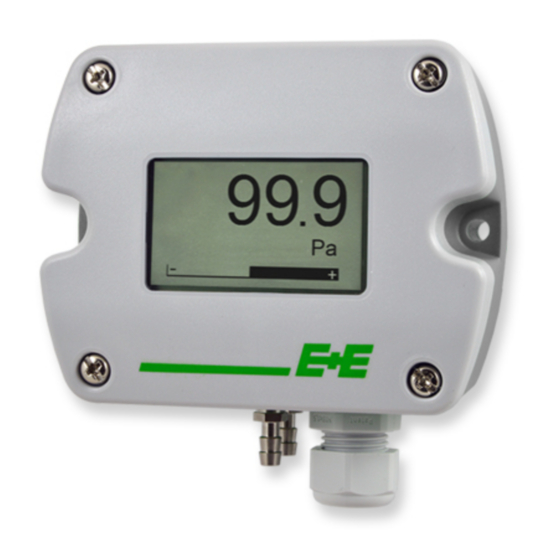
Low differential pressure sensor
Hide thumbs
Also See for EE610:
- User manual (16 pages) ,
- Quick manual (2 pages) ,
- User manual (28 pages)

Related Manuals for E+E Elektronik EE610


Summary of Contents for E+E Elektronik EE610
- Page 1 User Manual EE610 Low Differential Pressure Sensor BA_EE610 // v1.2 // Modification rights reserved...
- Page 2 E+E Elektronik Ges.m.b.H. accept warranty and liability claims neither upon this publication nor in case of improper treatment of the described products. The document may contain technical inaccuracies and typographical errors. The content will be revised and updated on aregular basis. The described products can be improved and changed at any time without prior notice.
-
Page 3: Table Of Contents
5.3.2 Analogue Version with PCS Settings or Digital Version ..................15 PCS10 Product Configuration Software ......................16 Maintenance and Service .........................16 Cleaning ..............................16 Repairs ................................16 Readjustment of EE610 ..........................16 6.3.1 Zero Point Adjustment ............................17 6.3.2 Span Point Adjustment ............................17 6.3.3 Return to Factory Adjustment ..........................17 6.3.4... -
Page 4: General
This symbol indicates safety information. It is essential that all safety information is strictly observed. Failure to comply with this information can lead to personal injuries or damage to property. E+E Elektronik® assumes no liability if this happens. This symbol indicates instructions. -
Page 5: Mounting, Start-Up And Operation
1.2.2 Mounting, Start-up and Operation The EE610 differential pressure sensor has been produced under state of the art manufacturing conditions, has been thoroughly tested and has left the factory fulfilling all safety criteria. The manufacturer has taken all precautions to ensure safe operation of the device. The user must ensure that the device is set up and installed in a manner that does not have a negative effect on its safe use. -
Page 6: Product Description
Dimensions FOR CONDUIT Values in mm (inch) INSTALLATION Pressure fittings Ø5 (0.2) high pressure low pressure Pressure connection set is included CABLE GLAND M16x1.5 in the scope of supply. (0.2) Fig. 2 Dimensions User Manual EE610 Low Differential Pressure Sensor... -
Page 7: Electrial Connection
Ausrichtung rechts out of range out of range Balken unterhalb ∆p < scale value low, ∆p > scale value high, -5 % of span +5 % of span Fig. 5 Out of range indication User Manual EE610 Low Differential Pressure Sensor... -
Page 8: Mounting And Installation
ƒ Use a Ø7.5 mm drill. Connect the pressure hose (included in the scope of supply) first to the EE610 and then to the ƒ nipples at the duct. Route the pressure hose for avoiding sharp bends which might lead to the hose obstruction (Fig. -
Page 9: Setup And Configuration
Mounting examples Setup and Configuration The EE610 is ready to use with its factory settings. The user can change the factory setup with the on- board DIP switches or the PCS10 Product Configuration Software and the USB configuration adapter (order code HA011066), please refer to the chapters below. -
Page 10: Select The Measurement Range With S1 And S2
DIP switches S1 to S9 as described below (S10 does not have any functionality). The function of the DIP switches is also indicated inside the EE610 front cover. 0 0 0 0 0 0 0 0 1 1 0 0 0 0 0 0 0 0 Fig. -
Page 11: Outputs
Setting the DIP switches to any other address than 0, overrules the default address (44) or the address set via software. Example: Address set to 3 (0000 0011 binary). 0 0 0 1 1 0 0 0 0 0 0 User Manual EE610 Low Differential Pressure Sensor... -
Page 12: Bacnet Protocol Settings
BACnet Protocol settings The recommended settings for multiple devices in a BACnet MS/TP network are 38 400, 8, None, 1. The EE610 PICS (Product Implementation Conformance Statement) is available on the website at www.epluse.com/ee610. BACnet address, baud rate can be set via: 1. -
Page 13: Modbus Register Map
Device status (bit decoded) 0x259 1) Register number starts from 1. 2) Protocol address starts from 0. 3) For Modbus protocol settings see Application Note Modbus AN0103 (available at www.epluse.com/ee610). 4) See chapter 5.2.7 Device Status Indication. 5.2.4 Modbus Register Map... -
Page 14: Freely Configurable Custom Modbus Map
0xBBA 1056 0x41F 6003 0x1772 FLOAT32 3004 0xBBB 1041 0x410 FLOAT32 3005 0xBBC 1042 0x411 1) Register number starts from 1. 2) Protocol address starts from 0. Tab. 11 Custom Modbus map example User Manual EE610 Low Differential Pressure Sensor... -
Page 15: Device Status Indication
Differential pressure measurement Unit: Pa, kPa, mbar, mm H O, inch WC, Layout: one line with limit bar User Manual EE610 Low Differential Pressure Sensor... -
Page 16: Pcs10 Product Configuration Software
HA011066 Fig. 12 EE610 configuration and adjustment Please note: The EE610 may not be connected to any additional power supply when using the USB configuration adapter HA011066. Maintenance and Service EE610 does not require any special maintenance, nevertheless it is recommended to perform a zero point adjustment every 12 month. -
Page 17: Zero Point Adjustment
The zero point adjustment is used to correct an eventual zero point deviation. a. Remove the tubes from both pressure connections of the EE610. By this the pressure equal on both connections. If the sensor has an auto-zero setting, the tubes do not need to be removed. -
Page 18: Technical Data
9 600, 19 200 and 38 400 Measured data types FLOAT32 and INT16 Protocol BACnet MS/TP Factory settings BACnet address 44 Supported Baud rates 9 600, 19 200, 38 400, 57 600 and 76 800 User Manual EE610 Low Differential Pressure Sensor... - Page 19 DIP switches PCS10 Analogue output without auto-zero Analogue output with auto-zero Digital interface without auto-zero Digital interface with auto-zero Configuration options see above or manual at www.epluse.com/ee610. User Manual EE610 Low Differential Pressure Sensor...
- Page 20 HEADQUARTERS SUBSIDIARIES E+E Elektronik Ges.m.b.H. E+E Elektronik China E+E Elektronik Germany E+E Elektronik Korea Langwiesen 7 18F, Kaidi Financial Building, Obere Zeil 2 Suite 2001, Heungdeok IT 4209 Engerwitzdorf No.1088 XiangYin Road 61440 Oberursel Valley Towerdong, 13, Austria 200433 Shanghai Tel.:...
Need help?
Do you have a question about the EE610 and is the answer not in the manual?
Questions and answers