
Related Manuals for E+E Elektronik EE75


Summary of Contents for E+E Elektronik EE75
- Page 1 User Manual EE75 Air / Gas Velocity Sensor Hardware and Software BA_EE75 // v14 // Modification rights reserved// 192310...
- Page 2 E+E Elektronik Ges.m.b.H. doesn‘t accept warranty and liability claims neither upon this publication nor in case of improper treatment of the described products. The document may contain technical inaccuracies and typographical errors. The content will be revised on a regular basis. These changes will be implemented in later versions.
-
Page 3: Table Of Contents
Resetting T to Factory Calibration: Self-Help / Maintenance Spare Parts / Accessories Technical Data CONFIGURATION General Information SOFTWARE Installation Menu Items File Help EE75 Configurator Start Analog Display Response Time Cross Section Probe Cable Switching Off Media Correction Calibration 4.9.1 Information on 1-point v/T Calibration 4.9.2... -
Page 4: General
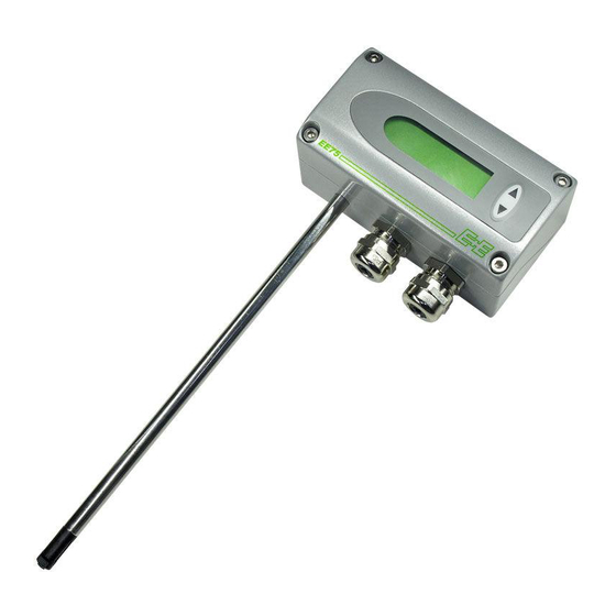
Product Description The EE75 velocity sensors were developed to obtain accurate measuring results over a wide range of velocities and temperatures. They have a robust metal enclosure to protect them against possible damage in rough... -
Page 5: Installation
Installation Before starting the installation please make sure that the upper and lower modules of the enclosures are not mixed up! Only with identical serial numbers the function of the sensor can be guaranteed within the specifications (see chapter 9. “Technical Data”). All dimensions in mm Installing the Enclosure 1. -
Page 6: Mounting Type T3 (Remote Probe)
Mounting Type T3 (Remote Probe) Selected probe length 3.3.1 Installing the enclosure Refer to chapter 3.1 3.3.2 Installing the probe (0.5") Refer to chapter 3.2.2 - Mounting with a Flange Mounting Type T26 (Remote Probe, Pressure- tight up to 10 bar / 145 psi Selected probe length 3.4.1 Installing the Enclosure... - Page 7 Removing the probe 1. If the sensor probe is installed in a pressure chamber, make sure that the pressure in the chamber and the ambient pressure are in equilibrium before removing the probe. 2. Hold the sensing probe/enclosure firmly. (Attention: Do not bend the connection cable) 3.
-
Page 8: Electrical Connections
Electrical Connections Connection Diagram Brown Black Measuring probe Orange Shield Analogue outputs Supply Green White USB-interface Black Shielding Connection Diagram with Plug Connections (Optional) Description: Connection assignment: Coupling for supply and analogue outputs (front view) OUT2 OUT1 Euro-Standard Description: Connection assignment: Plug for USB interface (front view) Vbus... -
Page 9: Operating Components
(for current output, e.g. 4 - 20 mA) EE75-TxA3 (for voltage output, e.g. 0 - 10 V) Jumpers for Setting the Velocity Response Time The EE75 allows users to set the velocity response time: a) Setting the velocity response time using jumpers: Jumper position Response time: (Also see chapter 5.1 - Circuit Board) -
Page 10: Display Module With Buttons (Optional)
Display Module with Buttons (Optional) 1. Measurand 2. Unit 3. Measurand selection and 4. Min/Max function 5. Measured value 6. Status line 3. Measurand Selection: 2. Unit 1. Measurand Velocity ft/min Pressing the ∆ or ∇ button switches between the various Temperature °C °F... -
Page 11: Velocity / Temperature Calibration
Velocity / Temperature Calibration The EE75 can be calibrated / adjusted using either the buttons on the optional display module or the USB interface and configuration software provided. Instructions for calibration: To achieve comparable results to the E+E factory setting, please note following: a) The adjustment should be done in a wind tunnel with homogeneous, low turbulent flow profile. -
Page 12: General Information On 2-Point V/T Calibration
The high calibration point should be in the upper third of the measuring range. Calibration / adjustment must be performed using the V/T-CAL HIGH function. Example: EE75 T3***HV23 - measuring range = 0 ... 2 m/s (0 - 400 ft/min). -
Page 13: Resetting To Factory Calibration
4. Use the buttons and cursor to select the menu item "CALIBRATION" and confirm the selection. 5. Select "T-Cal" and confirm the selection. 6.1 "1-point calibration": Select the calibration point as described in chapter 6.1.1. - If calibration point > 50% of measuring range, select "T-CAL HIGH" and confirm the selection. -
Page 14: Self-Help / Maintenance
Self-Help / Maintenance - If the measuring values are unrealistic, the first thing to check is the angle of inflow. - Also check the sensor element for soiling. If dust has collected on the element, blow it off carefully with oil-free compressed air. If there is anything else on the sensor, clean it carefully using isopropyl alcohol and allow it to dry. -
Page 15: Configuration Software
Administrator authorisations may be required for problem-free installation of the EE75 configuration software. 1. During installation do NOT connect the EE75 to the PC using the USB Port. 2. Run "Setup.exe" to install the EE75 configuration software. 3. The InstallShield Wizard for the EE75 configurator is launched. - Page 16 If the EE75 configuration software and the associated USB interface have been set up correctly, a connection has been assigned to the EE75 USB to UART Bridge Controller on your PC's Control Panel. See Start / Settings / Control Panel / System / Hardware / Device Manager 6.
-
Page 17: Menu Items
Start -> Settings -> Control Panel -> System -> Hardware -> Device Manager Exit: Closes the configuration software. Help Provides general information on the configuration software. EE75 Configurator Start The "Start" tab is used to initiate communication with the connected sensor. This function downloads the current sensor configuration and serial number. -
Page 18: Analog
Analog The "Analog" tab allows free configuration and scaling of the twoanalogue outputs Range: The drop-down input field is used either to select a standardised output signal (0-5 V, 0-10 V, 0-20 mA, 4-20 mA) or to specify a user-defined current/ voltage output range (e.g. -
Page 19: Cross Section
- The cable length is measured from the centre of the sensor element in the sensor head to the point where it enters the enclosure (PG / screw connection). - To increase the length of the probe cable, the instrument must be returned to E+E Elektronik. Configurations Software... -
Page 20: Switching Off
Calibration Velocity and temperature calibration is not only possible using the buttons on the integrated display, the EE75 can also easily be calibrated / adjusted using the configuration software. Note: The configuration software automatically distinguishes between the low and high calibration points. -
Page 21: Information On 1-Point V/T Calibration
5. Enter the velocity displayed by the reference system in the "Reference value" input field. 6. Clicking "Save" adjusts the EE75 measuring value with the reference value. 7. In the case of 1-point calibration, the process is now complete. 8. For 2-point calibration, repeat steps 2-7. -
Page 22: Measuring Values
4.10 Measuring Values The configuration software allows the EE75 measuring values to be queried periodically on the "Measuring Values" index card. If the "Activate automatic Query" function is activated, all measuring values are downloaded according to the specified interval and displayed in the desingated fields. - Page 23 Configurations Software...
- Page 24 HEADQUARTERS SUBSIDIARIES E+E Elektronik Ges.m.b.H. E+E Elektronik China E+E Elektronik Germany E+E Elektronik Korea Langwiesen 7 18F, Kaidi Financial Building, Obere Zeil 2 Suite 2001, Heungdeok IT 4209 Engerwitzdorf No.1088 XiangYin Road 61440 Oberursel Valley Towerdong, 13, Austria 200433 Shanghai Tel.:...
Need help?
Do you have a question about the EE75 and is the answer not in the manual?
Questions and answers