
Related Manuals for Air Liquide SAF-FRO DVU W500


Summary of Contents for Air Liquide SAF-FRO DVU W500
- Page 1 DVU W500 INSTRUCTIONS FOR OPERATION AND MAINTENANCE Cat n°: 8695-1215 Contact : www.SAF-FRO.com Date : 11/2013...
- Page 2 Arc welding and plasma cutting may be dangerous for the operator and persons close to the work area. Please ensure you read the operating manual carefully before use.
-
Page 3: Table Of Contents
CONTENTS 1 - GENERAL INFORMATION ............................................4 1.1. PRESENTATION OF INSTALLATION ....................................... 4 1.2. WELDING SET CONSTITUENT ........................................4 1.3. TECHNICAL SPECIFICATIONS ........................................4 1.4. DIMENSIONS AND WEIGHT..........................................4 2 - SETTING UP ................................................5 2.1. PRECAUTIONS ..............................................5 2.2. ASSEMBLY OF OPTIONS ..........................................5 2.3. -
Page 4: General Information
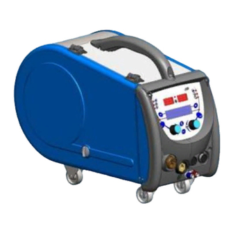
1 - GENERAL INFORMATION 1.1. PRESENTATION OF INSTALLATION The Wirefeeder DVU W500 has been specially developed for high standard applications that have particular requirements for the power source range of DIGIWAVE II, an expert range for manual applications Its optimized design makes it easy to use in a harsh environment whether for rolling (workshop trolley in option) or against exterior aggressive conditions (wet, dust, projections, etc…) The DVU W500 will allow you to achieve high quality welds with a nice appearance. -
Page 5: Setting Up
2 - SETTING UP 2.1. PRECAUTIONS To protect the front projections, hold closed the transparent cover. Ensure not to pinch the cables and gas pipes and water Ensure correct installation of power connections. The quarter turn connection must be well tightened Do not leave, liquid, hot material in contact with the cables. -
Page 6: Positionning The Wire
2.4. POSITIONNING THE WIRE Wire Feed unit Pin of the shaft of the reel locator Spool axle nut Flow meter option Wire speed setting Gas purge button Lever locker of the idlers Idlers Open the door of the wire-feed unit (I1) and ensure that it cannot fall. Unscrew the spool axle nut. -
Page 7: Instructions For Use
Displays the software version and the number of the wire feeder if several wire feeders are used Transit display « Air Liquide Welding » Work display depending on the state in which the installation was stopped. Adjustment in progress : When the power source is in a configuration where the setting is not allowed, the wire feeder’s interface is inactive and shows this message. -
Page 8: Welding Parameters Setting
Manual wire speed advance : To activate the wire speed advance, press and hold the button of manual wire speed advance. (I5). The wire speed is displayed and can be set with the left encoder (2) up to the limit of 12.5 m/min. - Page 9 Out of welding MIG program setting The scroll button ± (3) enables you to show the following lines in order to get access to the setting of the main welding parameters: line 1 Arc transfer Trigger mode Working mode (SYN, MAN FREE) not settable, for information line 2 Last welding current measure...
- Page 10 Specific case of the step mode : Go to the appropriate line for access to the parameters you want to set, and turn the right encoder to select the step you want to set: line 1 Working mode (SYN, MAN FREE) Arc transfer and step mode activated Trigger mode line 2...
- Page 11 line 7 Transit time Potentiometer settings The wire feeder may be connected to: • The potentiometer remote command • The potentiometer torch • The compatible push pull torch with potentiometers To be considered, the potentiometers must be configured into the power source (for more details see the power source instruction manual ). You have to specify the number of used potentiometers.
-
Page 12: Preview Ans Welding Measurement
TIG welding For more information about the setting of the TIG process, see the power source instruction manual § 3.4.1. line 1 TIG Process Trigger mode line 2 Last welding current measure Post soudage Last welding voltage measure line 3 welding current line 4 End of welding current... -
Page 13: Programs Management
The displayed values depend on the installation status: State Displayed values on (5) and (9) Indicator (8) Ajustement in Progress No values, these are replaced by dashes Out of welding Instructions or theoretical values In welding Direct measurements Blinks Post welding Last welding measures Fixed Notes :... -
Page 14: Wire Feeder Configuration
The line 1 contains, in this order, the following information • Program status (optional) • Program number • Program name The status information are: Floppy = The program has been modified since the last save. Verrou = Le programme est verrouillé. If the name of the program exceeds the capacity of the display, the name characters are continually shifted to allow a complete reading. - Page 15 Fault list description : Code Message LCD Signification Over max pw Exceeding the maximum allowed power from the current source – check that the welding program parameters do not exceed the characteristics of the current source (including Free mode) Overvoltage pw Over voltage of the 3 phase power supply of the power source of (tolerance 400V - 3 ~ 15 %/-20 %) - Verify the characteristics of the power supply Undervoltage pw...
-
Page 16: Options
4 - OPTIONS Pivot support, ref. W000279932 Gas flow controller, ref. W000275905 Wire feeder trolley, ref. W000275908 Simple remote control, ref. W000275904 RC-job II remote control ref. W000371925 Potentiometers torchs DIGITORCH 2 E 341 – 4m, ref. W000373831 DIGITORCH 2 E 341W – 4m, ref. W000373832 DIGITORCH 2 E 441W –... -
Page 17: Maintenance
5 - MAINTENANCE Twice a year, according to how often the set is used, inspect : The cleanliness of the wire feeder. The electrical and gas connections. Never clean or make repairs on the inside without first making sure that the set has been disconnected from the mains. Remove the wire feeder panels and vacuum up any dust and particles presente. -
Page 18: Recycling
5.3. RECYCLING The presence of the following components requires a specific end of life management (recycling): Electronic board of the front panel LCD screen on the electronic board of the front panel 5.4. SPARE PARTS see fold-out FIGURE 1 at the end of the manual) REF.
Need help?
Do you have a question about the SAF-FRO DVU W500 and is the answer not in the manual?
Questions and answers