Advertisement
Quick Links
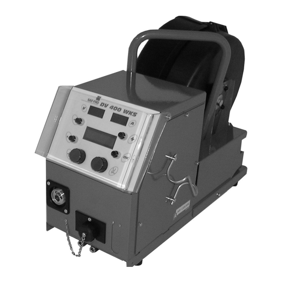
DV 400 WKS
Manuel d'emploi et d'entretien
FR
Use and maintenance manual
EN
Manual de utilizacion y mantenimiento
ES
Manuale per uso e manutenzione
IT
Manuel d'emploi et d'entretien
NL
Manuel d'emploi et d'entretien
RO
Návod na použitie a údržbu
SK
Cat n° : W 000 267 520
Rev
: E
Date : 09/08
/ Conserver ce livret d'instruction
/ keep this instruction booklet
/
Conservar este libro de instruciones
/ Conservare con cura
/ Conserver ce livret d'instruction
/ Conserver ce livret d'instruction
/
dôkladne uschovajte
Contact : www.saf-fro.com
Advertisement

Subscribe to Our Youtube Channel
Related Manuals for Air Liquide Saf-Fro DV 400 WKS


Summary of Contents for Air Liquide Saf-Fro DV 400 WKS
- Page 1 DV 400 WKS Manuel d’emploi et d’entretien / Conserver ce livret d’instruction Use and maintenance manual / keep this instruction booklet Manual de utilizacion y mantenimiento Conservar este libro de instruciones Manuale per uso e manutenzione / Conservare con cura Manuel d’emploi et d’entretien / Conserver ce livret d’instruction Manuel d’emploi et d’entretien...
- Page 2 Le soudage à l'arc et le coupage plasma peuvent être dangereux pour l'opérateur et les personnes se trouvant à proximité de l'aire de travail. Lire le manuel d'utilisation et l'instruction de sécurité. Arc welding and plasma cutting may be dangerous for the operator and persons close to the work area. Read the operating manual and safety instructions.
- Page 3 SOMMAIRE CONTENTS 1. INFORMATIONS GENERALES ................3 1.GENERAL INFORMATION..................3 1.1. PRESENTATION DE L'INSTALLATION ............3 1.1. PRESENTATION OF INSTALLATION ............3 1.2. COMPOSITION DE L’INSTALLATION ............3 1.2.WELDING SET CONSTITUENT ..............3 1.3. DESCRIPTION FACE AVANT ...............3 1.3.FRONT PANEL DESCRIPTION..............3 1.4. CARACTERISTIQUES TECHNIQUES DU DEVIDOIR .........3 1.4.
- Page 4 INHOUD CUPRINS 1. ALGEMENE INFORMATIE ..................39 1. INFORMAŢII GENERALE ..................39 1.1. VOORSTELLING VAN DE INSTALLATIE........... 39 1.1. PREZENTAREA INSTALAŢIEI ..............39 1.2. SAMENSTELLING VAN DE INSTALLATIE..........39 1.2. PĂRŢILE COMPONENTE ALE INSTALAŢIEI..........39 1.3. BESCHRIJVING VAN HET FRONTPANEEL ..........39 1.3. DESCRIEREA PĂRŢII FRONTALE .............39 1.5.
- Page 5 1. INFORMATIONS GENERALES 1.GENERAL INFORMATION 1.1. PRESENTATION DE L'INSTALLATION 1.1. PRESENTATION OF INSTALLATION Le dévidoir DV 400 WKS a été spécialement développé pour les applications où le The DV 400 WKS wire feed has been specially designed for applications where the matériel est exposé...
- Page 6 1.5. PRECAUTIONS 1.5. PRECAUTION ATTENTION : WARNING: - aux lexans possibilité de projection - protect Lexans from spray - ne pas coincer le câble - do not trap the cable - aux prises - take care with the plugs - ne pas laisser, de liquide, produit chaud en contact avec le câble - do not leave any liquid or hot product in contact with the cable Degrés de protection procurés par les enveloppes Degrees of protection provided by the covering...
- Page 7 2. MISE EN SERVICE 2. STARTING UP ATTENTION: la stabilité de l'installation est assurée jusqu'à une CAUTION : equipment stability is ensured up to an angle of inclinaison de 10°. 10°. 2.1. DEBALLAGE DE L'INSTALLATION 2.1. UNPACKING THE SET Retirer les différents éléments de leur emballage. Remove the various items from their packaging.
- Page 8 3. INSTRUCTIONS D'EMPLOI 3. INSTRUCTIONS FOR USE 3.1. MISE EN PLACE DU FIL DANS LE DV 400 WKS 3.1. POSITIONNING THE WIRE IN THE DV 400 WKS Le changement de fil de soudage s'effectue comme suit (après avoir mis le générateur The welding wire change takes place as follows (after having turned the power source hors tension) : OFF) :...
- Page 9 3.3. FONCTIONNEMENT 3.3. OPERATION Le dévidoir est reconnu automatiquement au démarrage du générateur, configurant The wire feed is automatically recognised when the generator is started, it configures le mode de fonctionnement de l’installation en fonction du numéro de programme the operating mode depending on the program number selected: sélectionné...
- Page 10 Bouton poussoir ou ‘Help’ : or ‘Help’ pushbutton: Un appui bref permet de passer à la fenetre de réglage suivante. When this pushbutton is pressed briefly the next setting window appears. L’appui maintenu sur ce bouton permet le défilement d’un message d’aide If the button is held down, a help message for the current screen is scrolled.
- Page 11 Ecran accessible par défaut en mode MANUEL. Default screen in MANUAL mode. - Tournez le codeur de gauche pour régler la vitesse fil de 1 à 25 m/min. - Turn the left-hand coder to set the wire speed between 1 and 25 m/mn. - Tournez le codeur de droite, pour régler la tension d’arc de 10 à...
- Page 12 Mode programme Programme mode Principe Principe Dans ce mode : In this mode: - Les réglages de vitesse fil (Vit fil), hauteur d’arc (HAr) et de réglage fin - The wire speed adjustment (Vit fil), arc height (HAr) and fine setting are sont deportés sur le dévidoir et donc ne sont plus accessibles sur le transposed to the wire feed and therefore no longer accessible on the generator;...
- Page 13 Bouton poussoir ’ ou ‘Help’: or 'Help' pushbutton: Cette touche est active hors et en soudage. This key is active whether or not welding in progress. L’appui bref (<1s) sur ce bouton permet le défilement des menus généraux Press this button briefly to scroll through the general menus. L’appui maintenu sur ce bouton permet le défilement d’un message d’aide correspondant If this button is held down, a help message for the currently active screen is à...
- Page 14 Procédure d’utilisation Operating procedure Hors soudage No welding in progress Ecran accessible en mode synergie : Screen accessible in synergy mode - tournez le codeur de gauche (Vit Fil ou Ep ou A) pour régler la valeur de - Turn the left-hand coder (Vit Fil or Ep or A) to set the left-hand value on the gauche sur l’afficheur display unit.
- Page 15 PRG V.Fil Longueur Arc Length of Arc Réglage pulse ou dynamisme Pulse or dynamism adjustment CYCLE Rotation Codeur Gauche Turn left Coder PRG Procede (lisse, SH+, pulse ou EE) Process (smooth, SH+, pulse or EE) PRG Fil (Fe, Inox, Alu, FF…..) SAUVEGARDE Wire (Fe, Stainless, Alu, FF…..) Rotation Codeur...
- Page 16 En soudage During welding En soudage, le prog en cours, U & I soudage sont affichés. During welding the currently active programme and welding voltage and current are displayed. Des que (V.Fil ou Ep ou A) sont modifiés avec codeur gauche ou (H.Arc) avec Any modification of V.Fil (wire speed) or Ep (thickness) or A with the left-hand coder codeur droit, le changement est affiché...
- Page 17 3.4. SECURITE 3.4. SECURITY Si le générateur se met en défaut, un message indique sur le dévidoir le type de If the generator is in default mode, a message on the wire feed shows the défaut. L’appui sur la touche OK permet d’acquitter le défaut. default type.
- Page 18 OPTIONS OPTIONS 1. Kit chariot, réf : W000 267 595 1. Chariot kit, ref : W000 267 595 2. Option débitlitre, réf : W000 267 596 2. Flowmeter option, ref : W000 267 596 3. Torche à potentiomètre, réf : W000 055072 3.
- Page 19 4. ENTRETIEN 4. MAINTENANCE 2 fois par an, en fonction de l’utilisation de l’appareil, inspecter : Twice a year, according to how often the set is used, inspect : la propreté du dévidoir the general cleanliness of the wire feeder les connexions électriques et gaz.
- Page 20 5. MAINTENANCE / PIECES DE RECHANGE 5. MAINTENANCE / SPARE PARTS 5.1 PIECE DE RECHANGE 5.1 SPARE PARTS see fold-out FIGURE 1 at the end of the manual) voir dépliant FIGURE 1 à la fin de la notice) Rep REF. SAF Désignation Désignation Item.
- Page 21 5.2. PROCEDURES DE DEPANNAGE DU DEVIDOIR 5.2. WIRE FEEDER UNIT DIAGNOSIS CHART Les interventions faites sur les installations électriques doivent être confiées Servicing operations carried out on electric installations must be performed à des personnes qualifiées pour les effectuer (voir MANUEL INSTRUCTIONS by persons qualified to do this kind of work (see SAFETY INSTRUCTIONS DE SECURITE).
- Page 22 dévidoir et le connecteur J2 sur carte wire feed base card embase dévidoir Check the presence of a potential of vérifier la présence d’une tension de 42VAC at the transformer terminals 42VAC aux bornes du transformateur GENERATEUR EN MARCHE / PAS DE DEVIDAGE, NI DE COMMANDE GAZ GENERATOR RUNNING / NO PAY OUT, NOR GAS CONTROL Connectique vérifier le branchement de...
- Page 23 1. INFORMACIONES GENERALES 1. INFORMAZIONI GENERALI 1.1. PRESENTACION DE LA INSTALACION 1.1. PRESENTAZIONE DELL’IMPIANTO La devanadera DV 400 WKS se ha desarrollado especialmente para las aplicaciones L'alimentatore DV 400 WKS è stato studiato specificamente per le applicazioni en las que el material está expuesto a un entorno hostil que necesita una concepción in cui il materiale è...
- Page 24 1.5. PRECAUCIONES 1.5. PRECAUTION ATENCIÓN : ATTENZIONE: - a los Lexan, posibilidad de proyección - ai lexan possibilità di proiezioni - de no pillar el cable - non schiacciare il cavo - a las tomas - alle prese - de no dejar liquido o un producto caliente en contacto con el - non lasciare liquidi o prodotti caldi a contatto col cavo cable Grados de protección proporcionados por las envolventes...
- Page 25 2. PUESTA EN SERVICIO 2. MESSA IN FUNZIONE ATENCIÓN: La estabilidad de la instalación está garantizada ATTENZIONE: la stabilità dell’impianto viene garantita fino ad hasta una inclinación de 10°. un’inclinazione di 10°. 2.1. DESEMBALAJE DE LA INSTALACIÓN 2.1. SBALLATURA DELL’IMPIANTO Retirar los diferentes elementos de su embalaje.
- Page 26 3. INSTRUCCIONES DE EMPLEO 3. ISTRUZIONI PER L’USO 3.1. COLOCACIÓN DEL HILO EN LA DV 400 WKS 3.1. POSIZIONAMENTO DEL FILO NEL DV 400 WKS El cambio de hilo de soldadura se realiza de la siguiente forma (después de haber Il cambio del filo di saldatura va eseguito come segue (con il generatore fuori puesto el generador fuera de tensión): tensione):...
- Page 27 3.3. FUNCIONAMIENTO 3.3. FUNZIONAMENTO La devanadera se reconoce automáticamente al iniciarse el generador, y configura el L'avvolgitore è riconosciuto automaticamente all'avvio del generatore, e la modalità modo de funcionamiento de la instalación en función del número de programa di funzionamento dell'impianto è configurata a seconda del numero di programma seleccionado: selezionato: Programa 0...
- Page 28 Botón pulsador o ‘Help’: Pulsante o ‘Help’: Una pulsación breve permite pasar a la siguiente ventana de ajuste. Una breve pressione di questo pulsante permette di passare alla finestra successiva di regolazione. La presión prolongada sobre el botón permite desplegar un mensaje de ayuda, La pressione prolungata del tasto permette di far scorrere un messaggio di giuda correspondiente a la pantalla en curso.
- Page 29 - Pantalla accesible por defecto en modo MANUAL - Schermata accessibile di default in modalità MANUALE - Se gira el codificommande à distanceor de la izquierda, para ajustar la - La rotazione del codificatore sinistro permette di impostare la velocità filo da 1 velocidad de hilo de 1 a 25 m/min.
- Page 30 Modo programa Modo Programma Principio Principio En este modo: In questa modalità: - Los ajustes de velocidad de hilo (Vit fil)), altura de arco (HAr) y ajuste fino se Le regolazioni di velocità filo (Vel.Filo), altezza d'arco (Ar) e di regolazione fine desvían a la devanadera y por lo tanto ya no puede accederse a ellos en el sono riportati sull'alimentatore e quindi non sono più...
- Page 31 Botón pulsador ’ O ‘HELP’: Pulsante ’ o ‘Help’ : Esta tecla está activa fuera y en soldadura. Questo tasto è attivo fuori ed in saldatura. Una presión breve (<1s) sobre el botón permite desplegar menús generales del MAD. La breve pressione (<1s) del tasto permette di far scorrere i menu generali della COMMANDE À...
- Page 32 Modo operativo Modo operativo Fuera de soldadura Fuori saldatura Pantalla accesible en modo SINERGIA: Schermata accessibile in modalità SINERGIA: - Se gira el codificommande à distanceor de la derecha (Vit Fil o Ep o A) para - Si gira il codificatore sinistro (Velocità Filo, Spessore o Altezza) per regolare il ajustar el valor de la izquierda en la pantalla valore di sinistra sul display.
- Page 33 PRG V.Fil Longitud Arco/lunghezza arco Ajuste pulsado o dinamismo Regolazione pulsata o dinamico CYCLE Rotación codificador izquierdo PRG Proceso (liso, SH+, pulsado o EE) SALVAGUARDA PRG Hil (Hie, Inox, Alu, FF…..) PRG Diam (0.8, 1.0, 1.2 ….) Rotación codificador izquierdo PRG Gas (Co2, Argon…..) Rotación codificador izquierdo...
- Page 34 En soldadura In saldatura En soldadura se visualiza el prog en curso, U & I soldadura. In saldatura, si visualizza il programma in corso, tensione ed intensità di saldatura. Apenas se modifica (V.Fil o Ep o A) con el codificommande à distanceor izquierdo o La modifica dei parametri (Velocità...
- Page 35 3.4. SEGURIDAD 3.4.SICUREZZA Si el generador pasa a fallo, un mensaje indica en el DEVANADERA el tipo de fallo. El Se si verifica un difetto del generatore, un messaggio indica sul comando a fallo puede eliminarse pulsando la tecla OK. distanza il tipo di difetto.
- Page 36 OPCIONES OPZIONI 1. Kit de carro, ref : W000 267 595 1. Kit carrello, cod : W000 267 595 2. Opción de caudalímetro, ref : W000 267 596 2. Opzione flussometro, cod : W000 267 596 3. Torcha à potenciometros , ref : W000 055072 2.
- Page 37 4. MANTENIMIENTO 4. INTERVISTA 2 veces por año, en función de la utilización del aparato, inspeccionar: 2 volte all’anno, in funzione dell’uso dell’apparecchio, verificare : la limpieza de la devanadera la pulizia dell’alimentatore las conexiones eléctricas y gas. i collegamenti elettrici e gas. ATENCIÓN ATTENZIONE No comenzar nunca una limpieza interna o una reparación sin...
- Page 38 5. MANTENIMIENTO / PIEZAS DE RECAMBIO 5. MANUTENZIONE / PEZZI DI RICAMBIO 5.1. PIEZAS DE RECAMBIO 5.1. PEZZI DI RICAMBIO Ver el desplegable figura 1 al final del manual) vedi opuscolo figura 1 alla fine delle istruzioni per l'uso) Rep / SAF Ref Désignación Désignation Pos / Rif.
- Page 39 5.2. PROCEDIMIENTOS DE REPARACION DE LA 5.2. PROCEDURE DI RIPARAZIONE DEVANADERA DELL’ALIMENTATORE FILO Las intervenciones realizadas en las instalaciones eléctricas deben ser Gli interventi eseguiti sugli impianti elettrici devono essere affidati a persone confiadas a personas cualificadas para realizarlas (véase el capítulo qualificate (vedi capitolo AVVERTENZE DI SICUREZZA).
- Page 40 VAC en los bornes del transformador Verificare la presenza di una tensione pari a 42VAC ai morsetti del trasformatore GENERADOR EN MARCHA / SIN DEVANADO, NI MANDO GAS GENERATORE IN MARCIA/ASSENZA DI SVOLGIMENTO E COMANDO GAS Conexiones verificar la conexión de la alimentación del Connettività...
- Page 41 1. ALGEMENE INFORMATIE 1. INFORMAŢII GENERALE 1.1. VOORSTELLING VAN DE INSTALLATIE 1.1. PREZENTAREA INSTALAŢIEI De haspelaar DV 400 WKS is speciaal ontwikkeld voor toepassingen waarbij het Cabestanul DV 400 WKS a fost dezvoltat special pentru aplicaţiile în care materialul materiaal aan een vijandige omgeving wordt blootgesteld, waardoor een versterkte este expus unui mediu ostil ce necesită...
- Page 42 1.5. VOORZORGSMAATREGELEN 1.5. PRECAUTION LET OP : ATENŢIE : - de lexans – spatten mogelijk - la lexani, posibilitate de proiectare a fragmentelor - dat de kabel niet bekneld raakt - pentru evitarea prinderii cablurilor - de aansluitingen - la prize - dat geen vloeistoffen of hete onderdelen met de kabel in contact - pentru evitarea contactului produsului cald lichid cu cablul komen.
- Page 43 2. INBEDRIJFSTELLING 2. PUNEREA ÎN FUNCŢIUNE OPGELET: de stabiliteit van de installatie wordt gegarandeerd tot een ATENŢIE: stabilitatea instalaţiei este asigurată doar până la o hoek van 10°. înclinare de 10°. 2.1. UITPAKKEN VAN DE INSTALLATIE 2.1. DESPACHETAREA INSTALAŢIEI De verschillende onderdelen uit hun verpakking halen. Se scot diversele componente din ambalajul aferent.
- Page 44 3. GEBRUIKSINSTRUCTIES 3. INSTRUCŢIUNI DE EXPLOATARE 3.1. AANBRENGEN VAN DE DRAAD IN DE DV 400 3.1. MONTAREA FIRULUI ÎN DV 400 WKS De verandering van lasdraad gebeurt als volgt (na de generator uitgeschakeld te Schimbarea firului (sârmei) de sudură se face după cum urmează (după ce aţi hebben): deconectat generatorul): 1.
- Page 45 3.3. WERKING 3.3. FUNCŢIONAREA De haspel wordt bij het starten van de generator automatisch herkend, zodat de Acest cabestan este recunoscut automat la pornirea generatorului, modul de werkingsmodus naar gelang het geselecteerde programmanummer geconfigureerd funcţionare a instalaţiei fiind configurat în funcţie de numărul programului selectat: wordt: Programma 0 STANDAARDMODUS...
- Page 46 Drukknop of ‘Help’: Butonul de sau ‘Help’: Met een korte druk op de knop gaat men naar het volgende afstelvenster. Apăsarea scurtă al acestuia permite trecerea la fereastra de reglaj următoare. Houdt men de knop ingedrukt, dan verschijnt er een helpbericht met betrekking tot het Ţinerea apăsată...
- Page 47 Scherm standaard toegankelijk in de HANDMATIGE modus Ecran accessibil implicit în mod de lucru MANUAL Met de linkercodeerder stelt men de draadsnelheid in van 1 tot 25 m/min. - Rotiţi selectorul din stânga pentru reglarea vitezei firului între 1 şi 25 m/min. Met de rechtercodeerder kan men de boogspanning van 10 tot 50v instellen.
- Page 48 - De 9 programma’s zijn volledig aan te passen; - Ordonatorul nu este disponibil decât în modul sinergie; - De sequencer bestaat alleen in de synergiemodus; - Mesajele de ajutor sunt disponibile pentru fiecare funcţie; - Voor iedere functie zijn hulpaanwijzingen beschikbaar; - Indicatorul JOB al generatorului se aprinde pentru a indica faptul că...
- Page 49 Drukknop ’ of ‘Help’: Butonul ’ sau ‘Help’: Deze toets is actief tijdens het lassen en niet-lassen. Această tastă este activă în timpul şi în afara sudurii. Drukt men kort (<1 sec.) op de knop dan kan men de algemene menu’s van de AB O apăsare scurtă...
- Page 50 Werkmethode Mod de lucru bij niet-lassen în afara sudurii Scherm toegankelijk in de modus synergie: Ecran accesibil în mod de lucru sinergic: Pt. a regla valoarea din stânga pe afişaj, se roteşte codificatorul din Met de linkercodeerder (Dr.Snelh. of D. of A) stelt men de linkerwaarde op stânga (Vit.
- Page 51 V.fil Booglengte Lungime arc Afstelling impuls of dynamisch Reglare prin impulsuri sau CYCLE CICLU Rotatie Codeerder Links Rotire codificator stânga PRG Procede (vlak, SH+, impuls of EE) Procedeu (continuu, SH+, impulsuri sau EE) BEWAREN SALVARE PRG Draad (Fe, Inox, Alu, FF…..) Fir (Fe, Inox, Alu, FF…..) PRG Diam (0.8, 1.0, 1.2 ….) Rotatie Codeerder Links...
- Page 52 Tijdens lassen In timpul sudurii Tijdens het lassen verschijnt het actieve prog, lasspanning & -intensiteit. În timpul sudurii se afişează programul în curs, tensiunea şi intensitatea sudurii. Van zodra men (Snelh.Dr. of D. of A) wijzigt met de linkercodeerder of (H.Boog) met Odată...
- Page 53 3.4. VEILIGHEID 3.4. SIGURANŢA Indien op de generator een fout optreedt, verschijnt het type defect in een bericht op Dacă generatorul se defectează, un mesaj afişat pe cabestan indică tipul de dévidoir. Drukken op de OK-toets leidt niet tot opslag van het lopende programma defecţiune.
- Page 54 OPTIES TILLVAL 1. Karkit, ref : W000 267 595 1. Set cărucior, ref : W000 267 595 2. Literdebiet-optie, ref : W000 267 596 2. Debitmetru opţional, ref : W000 267 596 3. Toort potentiometer, ref : W000 055072 3. Bec de sudura potentiometre, ref : W000 055072 De toorts met potmeter wordt, bij aansluiting op de haspelaar, automatisch herkend.
- Page 55 4. ENTRETIEN 4. ÎNTREŢINEREA 2 keer per jaar, naargelang van het gebruik van het toestel, het volgende controleren: În funcţie de utilizarea aparatului, inspectaţi de 2 ori pe an următoarele: de netheid van de generator la curăţenia cabestanului de aansluitingen voor elektriciteit en gas. conexiunile electrice şi ale gazului.
- Page 56 5. ONDERHOUD EN HERSTELLINGEN / 5. ÎNTREŢINEREA / PIESELE DE SCHIMB RESERVEONDERDELEN 5.1. RESERVEONDERDELEN 5.1. PIESELE DE SCHIMB Zie FIGUUR 1 onderaan de folder) a se vedea pliantul FIGURA 1 de la sfârşitul instrucţiunilor) Rep REF. SAF Omschrijving Specificaţie Item. P/N. SAF Frontpaneel Partea frontală...
- Page 57 5.2.PROBLEMEN & OPLOSSINGEN 5.2. PROCEDEUL DE DEPANARE AL CABESTANULUI De interventies op de elektrische installaties moeten gebeuren door Intervenţiile asupra instalaţiilor electrice trebuie încredinţate persoanelor bevoegde personen (zie hoofdstuk VEILIGHEIDSINSTRUCTIES). calificate în a le efectua (vezi capitolul MĂSURI DE SIGURANŢĂ). Bij de eerste activering is het eerste menu de taalkeuze.
- Page 58 MELDING GEEN MOTORSPANNING AANWEZIG PREZENŢA MESAJULUI: NO MOTOR VOLTAGE (LIPSĂ TENSIUNE LA MOTOR) Voeding Zekering F2 op de kaart van het Alimentare verificaţi siguranţa F2 de pe frontpaneel controleren cartela părţii frontale Connector B24 op de kaart van het verificaţi conectorul B24 de pe frontpaneel en connector J2 op de cartela părţii frontale şi kaart contact post controleren...
- Page 59 1 . VŠEOBECNÉ INFORMÁCIE 1.1. PREZENTÁCIA ZARIADENIA Odvíjač DV 400 WKS bol vyvinutý špeciálne pre použitie alebo materiál, ktorý je vystavený nepriaznivému prostrediu s nárokom na posilnenú konštrukciu. Je špecifikom expertného postupu generátora DIGIPULS pre ručné použitie. Tento odvíjač slúži zároveň na odvíjanie a ochranu cievky. Jeho optimalizovaný...
- Page 60 Stupne ochrany zabezpečené krytom Písmeno drôtu Ochrana prístroja Proti preniknutiu cudzích pevných telies od ∅ ≥ 12,5 mm Prvé číslo Druhé číslo Proti prenikaniu klapiek vody so škodlivým účinkom Proti prenikaniu dažďa (naklonený až do 60° vzhľadom na kolmicu) so škodlivými účinkami Udáva, že skúška overenia ochrany proti nepriaznivým účinkom spôsobeným prienikom vody sa vykonala so všetkými časťami materiálu v pokoji.
- Page 61 2. UVEDENIE DO ČINNOSTI UPOZORNENIE: stabilita zariadenia je zabezpečená až po naklonenie 10°. 2.1. ODBALENIE ZARIADENIA Vyberte jednotlivé časti z obalov. Upevnite odvíjací bubon drôtu na vozík podľa nasledujúcich pokynov. Zväzok napojte podľa pokynov na zadnú stranu odvíjacieho bubna a generátora. UPOZORNENIE: Pri zdvíhaní...
- Page 62 3. POKYNY PRE POUŽÍVANIE 3.1. VLOŽENIE DRÔTU DO DV 400 WKS Výmena zvarovacieho drôtu sa vykonáva nasledovne ( po tom, čo sme odpojili generátor od napätia) : Otvorte dvere na strane pre posuv drôtu. Odskrutkujte maticu vretena cievky. Vložte cievku so zvarovacím drôtom na vreteno.Skontrolujte, či je čap vretena na svojom mieste na cievke. Preložte maticu na vretene, tým, že ju otočíte v smere, ktorý...
- Page 63 3.3. FUNGOVANIE ODVÍJACIEHO BUBNA DRÔTU Odvíjač sa rozpozná automaticky pri štarte generátora s konfiguráciou režimu chodu zariadenia na základe zvoleného čísla programu: Program 0 ŠTANADRNÝ REŽIM Programy 1 až 9 REŽIM PROGRAMU Zmena programu sa uskutočňuje mimo zvárania pomocou tlačidiel PROG+ a PROG-. POZOR : Aby program fungoval, jeho zobrazená...
- Page 64 Zobrazenie Mimo zvárania: Obrazovka LCD udáva: - Príkazové hodnoty rýchlosti drôtu, šírky alebo intenzity a dĺžky oblúka; - Nastavenie konca; - Bezpečnostné hlásenia. Displeje hodnôt ukazujú príkazové hodnoty napätia a prúdu. Pri zváraní: Displej LCD udáva: - Automaticky prúd a namerané napätie; - Po stlačení...
- Page 65 Počas zvárania Obrazovka je prístupná implicitne v SYNERGICKOM režime U & I sa zobrazuje implicitne. Keď pomocou ľavého kódovača meníme V oblúka, Ep alebo A funkciu prezobrazenia na prednej strane) alebo pomocou pravého kódovača meníme H oblúka, zobrazí sa zmena. Modifikácia sa zobrazí...
- Page 66 v ručnom režime: V režime Lisse alebo pri pulznom zváraní rozsah nastavenia parametra napätie oblúka je od +10.0v do +50.0v. v synergickom režime: V režime Lisse alebo pri pulznom zváraní rozsah nastavenia dĺžky oblúka je od –50 do +50 vzhľadom na hodnotu určenú technológiou.
- Page 67 Zobrazenie Mimo zvárania: Displej LCD udáva: - Príkazové rýchlosti drôtu, šírky a intenzity; - Číslo spusteného programu, dĺžku oblúka a nastavenie konca; - Bezpečnostné hlásenia. Displeje meraní zobrazujú príkazové hodnoty napätia a prúdu. Pri zváraní: Displej LCD udáva: - Automaticky číslo spusteného programu, nameraný prúd a napätie; - Po stlačení...
- Page 68 Displej je prístupný, ak sme v polohe CYKLUS: Stlačením tlačidla sa dostaneme do SETUP ‘CYKLU’ Keď sme vybrali SETUP ‘CYKLUS’, otočíme ľavý kódovač. Tým umožníme zobrazenie MENU SETUP ‘CYKLUS’. Ak chceme nastaviť hodnotu nejakého menu, otočíme pravý kódovač. Ak chceme vyjsť z menu SETUP ‘CYKLUS’, musíme stlačiť tlačidlo OK alebo Z režimu môžeme vyjsť, ak stlačíme tlačidlo (v ktoromkoľvek z nižšie uvedenom menu) CYKLUS, modifikácie boli prijaté, ale nie sú...
- Page 69 V priebehu zvárania V priebehu zvárania sa zobrazuje aktuálny program, U & I zvárania. Keď zmeníme (Rých. Drôtu, Ep alebo A) pomocou ľavého kódovača alebo (výš. Oblúka) pomocou pravého kódovača počas zmeny i po ukončení zmeny v priebehu 2s sa zobrazí táto zmena Môžeme si zadať...
- Page 70 3.4. BEZPEČNOSŤ Ak nastane porucha na generátore, na diaľkovom ovládaní sa objaví druh chyby. Stlačenie tlačidla OK umožňuje zrušenie chyby. Zoznamy chýb zobrazených na diaľkovom ovládaní: na ohrievaní invertora Teplot_bezp Bezp_snímač_teploty snímač teploty alebo meracia reťaz teploty invertora sú zoskratované alebo odpojené príliš...
- Page 71 DOPLNKY 1. Súprava vozíka, réf : W000 267 595 2. Verzia s prietokomerom, réf : W000 267 596 3. Horak potenciometrami s prietokomerom, réf : W000 055072 Bubon s potenciometrom sa rozpozná automaticky po pripojení k odvíjaču. To má za následok: Automatickú...
- Page 72 4. ÚDRŽBA Dvakrát do roka, v závislosti na frekvencii používania prístroja, skontrolujte: čistotu generátora elektrické a plynové prípojky. UPOZORNENIE Nikdy nezačínajte vnútorné čistenie alebo opravu prístroja bez toho, aby ste sa vopred presvedčili, či je prístroj skutočne odpojený od siete. Odmontujte panely generátora a vysajte prach a kovové...
- Page 73 5. ÚDRŽBA / NÁHRADNÉ SÚČIASTKY 5.1 NÁHRADNÉ SÚČIASTKY pozri prospekt obrázok 1 na konci príručky) označenie názov Predná strana W000147185 Tlačidlo pre posun drôtu 2/5/10 W000265988 Modrá súprava tlačidiel W000147364 Tlačidlo pre ochranu pätice CAD Vnútorné prvky W000241667 Karta samčej zásuvky zväzkv W000241664 Karta zásuvky CAD W000148730...
- Page 74 5.2. POSTUP PRE ODSTRÁNENIE PORUCHY ODVÍJACIEHO BUBNA Zásahy na elektrických zariadeniach môžu vykonávať iba kvalifikované osoby (viď BEZPEČNOSTNÉ POKYNY). pri prvom uvedeni pod napätie, prvé menu, s ktorým sa stretneme je výber jazyka. ak tomu tak nie je, je to preto, lebo prístroj nebol znova spustený v závode.
- Page 75 NASTAVENIE NEZOHĽADNENÉ PRI ODVÍJACOM STUPNI, PRI CAD, PRI VYVINUTOM HORÁKU … skontrolujte stupeň blokovania na prednej strane ( pozri postup pre odstránenie poruchy prednej strany) GENERÁTOR PRI ZVÁRANÍ Problém posuvu drôtu skontrolujte, či sa nevyskytol preklz v mieste kladiek (tlak , referencia kladiek…) skontrolujte, či je horák správne vybavený...
- Page 82 DV 400 WKS 8695 1148 F/GB/D/I/E/P/NL/SPL/RO MODIFICATIONS APPORTEES Première page : L'ISEE passe à l'indice E suite au programme NEW OFFER (dans toutes les langues) Page : 11 Dans le tableau des pièces d’usure, remplacement de certaines références suite au programme NEW OFFER Modifications faites le 19.09.08.
Need help?
Do you have a question about the Saf-Fro DV 400 WKS and is the answer not in the manual?
Questions and answers