Table of Contents
Advertisement
Quick Links
Advertisement
Table of Contents

Related Manuals for Salus FC600


Summary of Contents for Salus FC600
- Page 1 FC600 FAN COIL THERMOSTAT- FULL USER MANUAL...
-
Page 2: Table Of Contents
3.10. Occupancy Sensor ............................... 32 3.11. Window Association Function ........................32 3.12. Identification Function ............................33 3.13. Pin / Unpin thermostat to the dashboard .................... 33 3.14. Service Settings ..............................34 3.15. Using / Adding OneTouch ..........................35 Fan Coil FC600 Instructions Manual... - Page 3 4.11. Switching from offline to online mode ....................58 4.12. Reset Function ............................... 60 4.12.1. In Local Mode (without Internet connection) ..............60 4.12.2. Via App .............................. 60 4.13. Cleaning and Maintenance ..........................61 4.14. Technical Specification ............................61 4.15. Warranty ..................................62 Fan Coil FC600 Instructions Manual...
-
Page 4: Introduction
1.3. Product Overview The Fan Coil thermostat (FC600) is a complex device that can help you control your room temperature and fan speed in a large number of configurations. It can be connected to a 2 or 4 pipe system and can be associated with multiple sensors (occupancy sensors, window sensors, pipe sensors), increasing by that the quality and speed of the temperature management in your home, office, hotel etc. -
Page 5: Operation Manual (Offline Mode)
2 valves (in 2 pipes the V1 input controls heating and cooling, in 4 pipes V1 controls heating and V2 controls cooling). FC600 can also control the FAN speed in 3 levels: low, medium or high, in order to maintain the room temperature. -
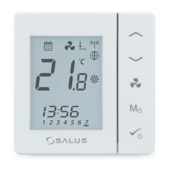
Page 6: Lcd Icon Description
8. Temperature unit 21. Program number 9. Heating Mode ON 22. S1/COM Sensor indicators 10. Cooling Mode ON 23. S2/COM Sensor indicators 11. STANDBY mode 24. Room/set point temperature 25. Set point temperature indicator 12. Occupancy/vacancy sensor Fan Coil FC600 Instructions Manual... - Page 7 25. Set point temperature indicator Man in door when presence detected , empty Icon appears when a new setpoint temperature is door when not. being set. 13. Lock function This icon indicates the keys of the device are locked. Fan Coil FC600 Instructions Manual...
-
Page 8: Power Up
After FC600 has been installed accordingly to your system (for the installation and different systems description please refer to the Installer Section in chapter 4) it will go into STANDBY Mode. To start using your FC600 and adjust room temperature, create schedules and operate the fan you will need to wake it up. Simply press the button for 3 seconds. -
Page 9: Temperature Setpoint
3 sec Thermostat is On. When the main settings are ... or heating ...heating only... done - FC600 will go to Standby cooling . Confirm by mode. Press OK for 3 sec pressing OK to turn ON the FC600. Note: Steps from 8-10 (choosing heating/cooling or both) is available only for the manual heat/cool changeover. -
Page 10: Fan Control
Fan speed on Auto / Off. When fan is Off all dots and Auto icon disappears Press to select fan speed By default, the fan is on only when the Fan Coil calls for heating or cooling. Fan Coil FC600 Instructions Manual... -
Page 11: Operation Mode Selection
The heat icon indicates that the thermostat is in Heating Mode. You can set a temperature higher than the current temperature and the Fan Coil will maintain it until you set a new setpoint. Fan Coil FC600 Instructions Manual... - Page 12 Eco Mode with auto heat/cool changeover. The temperature will be set using Eco temperature setpoint. When in Eco Mode, the thermostat will use Eco set point to control the room temperature. You cannot change the temperature in Eco mode. Fan Coil FC600 Instructions Manual...
- Page 13 Eco Mode. The snowflake icon indicates that the thermostat is in Heating Mode. When in Eco Mode, the thermostat will use Eco setpoint to control room temperature. You cannot change the temperature in Eco Mode. Fan Coil FC600 Instructions Manual...
-
Page 14: Other Mode Button Functions
As default, the thermostat is configured as digital (non-programmable) thermostat. If you would like to change the thermostat from digital to programmable, you need to change d00 parameter from 0 to 1 (please see page 49). Fan Coil FC600 Instructions Manual... -
Page 15: Setting Date And Time
Confirm the selection using using using using if programmable only After you have completed time and date setup, you can start setting up your schedules and programs. Using , select the day. Confirm the selection using Fan Coil FC600 Instructions Manual... -
Page 16: Setting Schedules
3-4, as only one schedule needs to be created. If both modes are available - 2 schedules need to be created (one for heating, another for cooling). Using , select the mode for which you want to set the schedule: Cooling Mode Heating Mode Confirm the selection using Fan Coil FC600 Instructions Manual... - Page 17 If you are programming every day individually, you will have to set the programs from 1- 6 for Monday, then Tuesday, Wed, Thu, Fri, Sat and Sun. If you are programming all week the same, you will have to set all the 6 programs just once. Fan Coil FC600 Instructions Manual...
- Page 18 • The starting time of the next program cannot be equal or earlier than the previous one. For example in the first program starts at 8:00, the next has to start at least 8:10 etc. Fan Coil FC600 Instructions Manual...
-
Page 19: Offset Function
Frost Protection temperature the heating valve will open and and the fan will be turned on at maximum speed. 3 sec Thermostat in STANDBY / Frost Long Press to enter STANDBY Protection Mode. / Frost Protection Mode. Fan Coil FC600 Instructions Manual... -
Page 20: Key Lock Function
External sensor open or external sensor is not connected External sensor short circuit When the external sensor is reconnected or fixed, thermostat will return to Normal mode and display the current room temperature. When Err XX appears, the thermostat will be closed. Fan Coil FC600 Instructions Manual... -
Page 21: Standby Mode
You can always switch back off STANDBY Mode by long pressing the OK button. All relay outputs immediately change to OFF, regardless of the previous operating mode (heat, cool, auto heat/cool). All your preset settings will be stored. When FC600 works in Standby mode, the Frost Protection is running. -
Page 22: Operation Manual (Online Mode)
3.1. Quick Overview This section will show how to use your Fan Coil with the Universal Gateway and the Salus Smart Home App. In order to do that, you will be needing a Salus Universal Gateway UG600/UGE600, the Salus Smart Home App and Internet connection. -
Page 23: App Screen Icon Description
Edit thermostat name On/Off/Schedule/Eco/Hold Tap for submenu Manually adjust temperature Set Temperature Fan Speed/Off/On Tap for submenu Current Temperature Find your device Window sensor button Settings Button Lock/Unlock thermostat Pin/Unpin thermostat to dashboard Fan Coil FC600 Instructions Manual... -
Page 24: Device Name Change
Fan Coil FC600 Instructions Manual... -
Page 25: Heat/Cool Selection
When thermostat is in COOLING mode and is calling for COOL Thermostat tile on Thermostat tile on the dashboard when the dashboard when thermostat is in thermostat is in Cooling Mode and Heating Mode and calls for cooling. calls for heating. Fan Coil FC600 Instructions Manual... -
Page 26: Work Status
When the thermostat runs is Permanent Hold, the hand icon will be displayed on the App screen. The thermostat is in Tap to enter sub-menu. Tap hand icon permanent hold. Fan Coil FC600 Instructions Manual... -
Page 27: Eco Mode
When the occupancy sensor does not detect presence, the man in door symbol disappears and the Eco Mode via app is enabled. This is the default d34 setting. For more information regarding the installer mode, please check page 54. Fan Coil FC600 Instructions Manual... -
Page 28: Standby Mode
Note: After the thermostat exits Standby Mode, all the settings will be restored. Tap the work status icon. Select Off The thermostat is running in STANDBY Mode. Tap On/Off icon. Thermostat in previous Select On mode. Fan Coil FC600 Instructions Manual... -
Page 29: Setting A Schedule For The Thermostat
Tap Add interval. Add a start time. Add. Note: The time should be in hh:mm format and the temperature value should be a number between 5 and 40. Decimal digits must end in 0 or 5. Fan Coil FC600 Instructions Manual... - Page 30 You can edit successfully updated. using the steps 4-8 and them by pressing the tap Update. pencil icon You can delete undesirable intervals by: Interval deleted. Tap Sign . Delete button will appear. Tap it. Fan Coil FC600 Instructions Manual...
-
Page 31: Fan Control
"d37" (permission to unlock the thermostat from the device level) or the value "d43" (enabling the change of the set temperature despite the locked buttons) - more information in chapter 4 - Installer Mode. Fan Coil FC600 Instructions Manual... -
Page 32: Occupancy Sensor
Please see below. To add a window sensor to you system, please refer to SW600/OS600 manual on www.salus-manuals.com Tap Save to save your... -
Page 33: Identification Function
Thermostat is pinned to the Thermostat is pinned to Thermostat unpinned. dashboard. the dashboard. Tap unpin. Tap Equipment. Tile is no longer visible. To Tap All equipment. Tap thermostat. to pin back. access the thermostat go to Menu. Fan Coil FC600 Instructions Manual... -
Page 34: Service Settings
This menu allows you to change settings on your thermostat. Please read more in the Installer Manual section about more detail on how to access the settings with a full description of the parameters. See page 51. Fan Coil FC600 Instructions Manual... -
Page 35: Using / Adding Onetouch
Press the button to get Go to home screen by Your thermostat is set One Touch tile the OneTouch running. tapping to 21 ⁰C. appears on your home screen and thermostat went blue meaning it is cooling down. Fan Coil FC600 Instructions Manual... -
Page 36: Installer Manual
4.2. Proper positioning of the thermostat The ideal position to locate the FC600 thermostat is about 1.5m above floor level, in a location where the thermostat is accessible, reasonably lit and free from extremes of temperature and draughts. Do not mount the thermostat on an outside wall, above a radiator or in a location where it may be subjected to direct sunlight. -
Page 37: Idea Diagrams
4.3. Idea diagrams Below you can find some possible usage diagrams for the Fan Coil thermostat, depending on the on your system and components. • 2 pipe, heating only • 2 pipe, cooling only Fan Coil FC600 Instructions Manual... - Page 38 • 2 pipe, heating OR cooling • 4 pipe, heating AND cooling Fan Coil FC600 Instructions Manual...
- Page 39 External switch (ON/OFF) (e.g. an occupancy sensor, launching ECO or Standby mode) Pipe temperature sensor (allows the fan to be working or not) Air temperature sensor or external room temp. sensor (FC600 will display temperature from the sensor connected to T2. Internal temperature sensor will be ignored)
-
Page 40: Wiring Options
- Air temperature sensor or external room temp. sensor (or pipe sensor - only in 2-pipe system)* (active T2 sensor disable temperature measurement in thermostat) Occupancy sensor or external sensor - Zone valve Common Terminal Fan Coil FC600 Instructions Manual... -
Page 41: Terminals Explanation
Occupancy sensor is connected to the S2/COM The temperature read by the sensor will be terminal (e.g.: hotel card). displayed on the Fan coil LCD. The internal sensor in the Fan coil will not be used. Default setting: NoFn Fan Coil FC600 Instructions Manual... - Page 42 Heating Mode and turn On/Off the fan, if selected. An external pipe sensor is connected to the S1/COM terminal, that tells the fan to run or not. The type of SenS sensor connected to the S1/COM terminal need to be NTC 10kOhm. Fan Coil FC600 Instructions Manual...
-
Page 43: Wall Mounting
Caution: The installation must be carried out after the thermostat is disconnected from the power supply. Connecting the mains voltage 230V ~ to the sensor terminals effectively damages the thermostat and creates danger of electric shock. Before power up, check if the wires are properly connected. Fan Coil FC600 Instructions Manual... - Page 44 6 mm 60 mm FC600 is designed for flush mounting in a 60 mm wall box. Fit the front part of the casing to the top edge and make sure Make sure the back cover is in place in the appropriate position the pins are properly positioned.
-
Page 45: Online Mode
To begin the pairing process the Gateway should be plugged into the power source and connected to the Internet. Also, make sure that the UG is added to your Salus Smart Home App. For the installation of the Universal Gateway, please refer to the UG600/UGE600 manual at www.salus-manuals.com Make sure that your Universal Gateway is added to the App. - Page 46 2 Pipe or 4 Pipe more info on one Touch, dashboard. Tap Next. configuration and then tap please check page 35. This Next to go to the next step. will NOT influence your settings. Fan Coil FC600 Instructions Manual...
- Page 47 Tap Complete Tap Finish to go to the next external inputs on S2 sensor. Please see page 41 on setup. step. The Fan Coil tile will external sensors. Tap Next. appear on your screen. Fan Coil FC600 Instructions Manual...
- Page 48 App, or on the device itself. Please see next page for a list of icons displayed on the screen in your App. For a full list of icons on your Fan Coil screen please see page 6. Fan Coil FC600 Instructions Manual...
-
Page 49: Installer Parameters
To change the installer parameters when the device is connected to the App, please see the page below. 4.8.2. Switching from non-programmable to programmable thermostat After first power up, FC600 is non programmable by default. If you would like to switch it to programmable thermostat in local mode, please follow below steps:... -
Page 50: In Online Mode (Via App)
Use again to modify the value for the parameter. The d00 will flash. The d00 will flash. Press OK to enter Choose paramenter using Choose paramenter using parameter and then press again to exit parameter. Fan Coil FC600 Instructions Manual... - Page 51 Note: During the installer mode, if no any button pressed, then FC600 should save the changes and go to main menu in 15minutes. Parameter Default Type of setting Description number Values Type of thermostat 0 = Non-programmable - you cannot set schedules to your thermostat.
- Page 52 0 = manual - the user can lock the keys manually via device or App. 1 = Auto (thermostat will lock the keys after 5 minutes since last button press) 2 = Unlocked the user can't lock the keys. Fan Coil FC600 Instructions Manual...
- Page 53 TPI heat control CPH 3 – 12 on/off cycle per hour TPI cool control CPH 3 – 12 on/off cycle per hour Dead zone Comfort 1.0 to 5.0K mode (4 pipe only) Fan Coil FC600 Instructions Manual...
- Page 54 ECO mode if you select ”0”, or go to STANDBY ECO mode or model if you select ”1”(for details, please see below) STANDBY mode. OFFSET of the second From -3⁰C to +3⁰C 0⁰C sensor connected do S2/COM (parameter available only when d03 = 2) Fan Coil FC600 Instructions Manual...
- Page 55 It depends on the initial configuration of the thermostat and can only be changed after a device reset (i.e. after restoring factory settings). Some parameters will be visible / invisible depending on the setting of main parameter d01 (fan coil type: 0 = 2-pipe; 1 = 4-pipe). Fan Coil FC600 Instructions Manual...
-
Page 56: Fan Operation In Heating And Cooling Mode
External switch (ON/OFF) (e.g. an occupancy sensor, launching ECO or Standby mode) Pipe temperature sensor (allows the fan to be working or not) Air temperature sensor or external room temp. sensor (FC600 will display temperature from the sensor connected to T2. Internal temperature sensor will be ignored) -
Page 57: Fan And Valve Operation (V1) Including Pipe Sensor In A 2-Pipe System With The Use Of "D24" And "D25" Parameters
Stage VI - the same as stage II t [°C] pipe temperature START START d25 = 30°C d25 -2°C STOP setpoint temperature = 20°C STOP STOP d24 +2°C d24 = 10°C START T [s] Cooling Heating Cooling Heating Mode Mode Mode Mode Fan Coil FC600 Instructions Manual... - Page 58 4.10.2. Fan operation in cooling mode If FC600 is in cooling mode and has the task of cooling the room, the valve V1 opens. The fan will start only when the pipe reaches the temperature below the "d24" value. If the temperature of the pipe will increase by 2°C above the parameter "d24", the fan will be switched off and the valve will still be open.
-
Page 59: Switching From Offline To Online Mode
To begin the pairing process the gateway should be plugged into the power source and connected to the Internet. Also, make sure that the UG is added to your Salus Smart Home App. For the installation of the Universal Gateway, please refer to the UG600/UGE600 manual on salus-manuals.com Make sure that your Universal Gateway is added to the App. - Page 60 The Fan Coil should appear Select device and tap Rename your device and automatically into FC App on screen. Connect equipment. tap Next. screen. Now, tap Finish to The thermostat tile appears complete the setup. on the dashboard. Fan Coil FC600 Instructions Manual...
-
Page 61: Reset Function
You will not be able to operate any changes to it. An alert screen sign will appear on your screen. If you tap it, it will tell that th Fan Coil left the system. Fan Coil FC600 Instructions Manual... -
Page 62: Cleaning And Maintenance
4.13. Cleaning and Maintenance The FC600 Fan Coil requires no special maintenance. Periodically, the outer casing can be wiped clean using a dry cloth (please DO NOT use solvents, polishes, detergents or abrasive cleaners, as these can damage the thermostat). There are no user serviceable parts within the unit; any servicing or repairs could only be carried out by Salus Controls or their appointed agents. -
Page 63: Warranty
4.15. Warranty SALUS Controls warrants that this product will be free from any defect in materials or workmanship, and shall perform in accordance with its specification, for a period of five years from the date of installation. SALUS Controls sole liability for breach of this warranty will be (at its option) to repair or replace the defective product. - Page 64 NOTES Fan Coil FC600 Instructions Manual...
- Page 65 SALUS Controls is a member of the Computime Group. Maintaining a policy of continuous product development SALUS Controls plc reserve the right to change specification, design and materials of products listed in this brochure without prior notice. Issued: VII 2020...
Need help?
Do you have a question about the FC600 and is the answer not in the manual?
Questions and answers
Kako otkljucati