Salus RT500 Instruction Manual
Salus programmable thermostat instruction manual
Hide thumbs
Also See for RT500:
- Instruction manual (25 pages) ,
- Instruction manual (1 page) ,
- Easy user manual (1 page)
Advertisement
Sales +44 (0) 8700 766900
Technical +44 (0) 8700 766902
Salus Controls plc
Enterprise Park, Bala
Gwynedd, LL23 7NL
Regional offices, England & Scotland.
Web: www.salus-tech.com
Email: sales@salus-tech.com
Maintaining a policy of continual product
development Salus Controls plc. reserve the right to
change specification, design and materials of
products listed in this brochure without prior notice.
Manual Issue No. IM-RT500-001
In st ru ct io n M a nu al
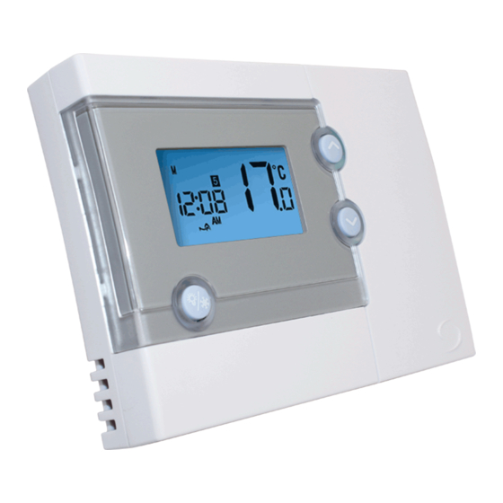
Programmable
THERMOSTAT
for Model No. RT500
Thank you for purchasing this Salus product
- if installing for someone else, please ensure that
the instructions are handed to the householder.
Warning - Please read this manual prior to
installation or use.
Shock Hazard
This unit must be installed by a competent person,
in accordance with BS 7671 (the IEE Wiring
Regulations), or other relevant national regulations
and codes of good practise.
Always isolate the AC Mains supply before removing
the unit from the Industry Standard Back Plate.
Advertisement
Table of Contents

Related Manuals for Salus RT500


Summary of Contents for Salus RT500
- Page 1 Regulations), or other relevant national regulations and codes of good practise. Maintaining a policy of continual product development Salus Controls plc. reserve the right to Always isolate the AC Mains supply before removing change specification, design and materials of the unit from the Industry Standard Back Plate.
-
Page 2: Specification
Switch/Jumpers Function The RT500 must be located where it would not be This appliance is Double Insulated except at the Earth Parking termin subjected to extraneous heat gain/loss (such as above Temperature Span 1 Jumper for +/-0.5°C (factory... -
Page 3: User Guide
pers: Enter cable to rear of back plate. Function Status after Reset or Power on User Guide Securely fix back plate to wall surface or recessed back box ect the jumper positions required Operation Mode Normal mode using holes provided. actory presets-these jumpers are Function Room Temperature... -
Page 4: Clock Setting Mode
Status after Reset or Power on User Guide Default Programme Clock Setting Mode: Normal mode • Press and hold SET and SELECT in No Function Program Weekday (M to F) Weekend (SA to SU) 22.0°C, to be renewed mode for 3 seconds to enter Clock settin Increase Setpoint Temperature within 5 seconds Time: 6:00am... -
Page 5: Program Setting Mode
Press SELECT at any time to confirm the s lt Programme Clock Setting Mode: Program Setting Mode: "Hour" is flashing to indicate that it is the s • Press and hold SET and SELECT in Normal 5-2 days program selected item to be adjusted. - Page 6 Press SELECT at any time to confirm the selection. 5-2 or 7 days program am Setting Mode: 7 days program selected "Hour" is flashing to indicate that it is the selected • The PROG indicator is displa program selected • 5 different sets of Time and Setpoint item to be adjusted.
-
Page 7: Frost Protection
5-2 or 7 days program am selected Frost Protection: Temporary Override: • The PROG indicator is displayed accordingly to Time and Setpoint • Press and hold BL/FROST in Normal mode for 3 • Press when reviewing Setpoint indicate the program number. be set for each Day of Week. - Page 8 • The setting range is 10°C - 35°C in steps of Protection: Temporary Override: Reviewing Setpoint T 0.5°C. and hold BL/FROST in Normal mode for 3 • Press when reviewing Setpoint • Press to review the S • Setpoint Temperature will stop flashing when a ds to activate the Frost Protection.
-
Page 9: Lcd Backlight
is 10°C - 35°C in steps of Reviewing Setpoint Temperature: Low-Battery Detectio • Press to review the Setpoint Battery voltage is sampled every ature will stop flashing when a temperature. battery voltage drops to a certa en flashes again once the key is Battery warning indicator appea When any program is running, the LCD will show the program Setpoint temperature with the "SET"... -
Page 10: Low-Battery Detection
Low-Battery Detection: Sleep Mode: Battery voltage is sampled every minute. When the • Press and hold in Normal mode for 3 battery voltage drops to a certain level, the Low- seconds simultaneously to enter the Sleep mode. Battery warning indicator appears. •...
Need help?
Do you have a question about the RT500 and is the answer not in the manual?
Questions and answers
How do you change/access the battery in a Salus RT500 unit?
To change the battery in a Salus RT500 unit, follow these steps:
1. Ensure the mains supply to the system is isolated before removing the thermostat.
2. Open the battery compartment on the RT500.
3. Remove the two ‘AA’ alkaline batteries.
4. Insert two new ‘AA’ alkaline batteries, ensuring they are correctly oriented according to the polarity markings.
5. Close the battery compartment securely.
6. Do not restore the mains supply until all associated items are fully installed.
Always follow safety precautions and consult a qualified electrician if unsure.
This answer is automatically generated