
Related Manuals for Salus ST620RF


Summary of Contents for Salus ST620RF
- Page 1 ST620RF Manual Version 005 CMYK:Layout 1 1/9/10 11:56 Page 1 S-Series Digital Thermostat Model No ST620RF Instruction Manual...
- Page 2 ST620RF Manual Version 005 CMYK:Layout 1 1/9/10 11:56 Page 2 ST620RF INSTRUCTION MANUAL...
- Page 3 EC Marking Directive 93/68/EEC SAFETY INFORMATION These instructions are applicable to the Salus Controls model stated on the front cover of this manual only, and must not be used with any other make or model. These instructions are intended to apply in the United Kingdom only, and should be followed along with any other statutory obligations.
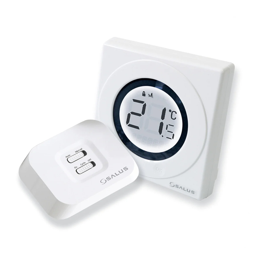
- Page 4 The ST620RF from Salus Controls is a stylish and accurate 5/2 or 7 day programmable electronic thermostat with a large, easy to read Liquid Crystal Display (LCD).
-
Page 5: Installation
TV sets, computers, etc.), and is not mounted on or in close proximity to large metal objects. Installing the ST620RF in enclosed areas such as cellars and basements is not recommended. BOILER RECEIVER COM N/O MAINS FEED Thermostat loop (Remove link) Live Feed ST620RF INSTRUCTION MANUAL... - Page 6 ST620RF, but a parking terminal is provided to connect an Earth wire if one is present. These electrical connections are shown in the table below: Terminal Function Common Contact (volt free input) Normally Open Contact (volt free output) Earth Parking (No electrical connection) Incoming Mains - Live Incoming Mains - Neutral ST620RF INSTRUCTION MANUAL...
- Page 7 Ensure that the batteries are inserted correctly, paying careful attention to the polarity markings on the battery and next to the battery holders. After inserting the batteries, refit the ST620RF case and retighten the securing screw. ST620RF INSTRUCTION MANUAL...
-
Page 8: Pairing Receiver/Control Centre
10 minutes before returning to NORMAL mode. On the Control Centre: The Arrow key is not active when the ST620RF is in NORMAL mode. To access the Menu screens, press the OK key twice. The first menu displayed is the PROGRAMME menu: ST620RF INSTRUCTION MANUAL... - Page 9 Pressing the Arrow key will return the ST620RF to NORMAL mode. The thermostat will also return to NORMAL mode after 10 seconds if no Key is pressed or if no movement is detected on the Touch Ring. ST620RF INSTRUCTION MANUAL...
- Page 10 Receiver and Control Centre. This is a quick and easy way to directly link the units in many applications. ST620RF INSTRUCTION MANUAL...
- Page 11 Receiver has established communication successfully, the green Power LED will flash for 4 seconds to indicate the process has completed correctly. The Control Centre will transmit only when there is a need to control the heating system. ST620RF INSTRUCTION MANUAL...
-
Page 12: Receiver Led Indicators
Receiver is either receiving a new RF address code in SYNC mode, flashing or has failed to store the new RF address code when in SYNC mode Yellow Receiver is in Failsafe mode after no RF signal received for over 1 hour ST620RF INSTRUCTION MANUAL... - Page 13 If the Reset Button is pressed, the ST620RF will behave in the same way as described above, except that any previously saved user settings stored in the internal memory will be deleted and overwritten with the default settings. ST620RF INSTRUCTION MANUAL...
- Page 14 (in Celsius), and the bottom row is an alphanumeric display for menu and status messages. The symbols around the outside of the display are status indicators – an explanation of what these indicators mean is shown on the next page. ST620RF INSTRUCTION MANUAL...
- Page 15 RCC indicator Indicates the status of the Radio Controlled Clock Service indicator Indicates Service function is active Frost Mode indicator Indicates frost setting is turned on Touch Lock indicator Indicates touch lock is activated ST620RF INSTRUCTION MANUAL...
- Page 16 Hold for two seconds sets the unit back to NORMAL mode Reset Button Resets the programmable thermostat to default (original factory) settings except Service setting (when Service is on) Slide Switch Activates and deactivates the key lock function (prevents accidental changes) ST620RF INSTRUCTION MANUAL...
- Page 17 Switches Receiver output on and off in a 15 minute cycle (4 minutes on, 11 minutes off) Turns Relay output OFF SYNC Button Enables RF signal synchronisation with ST620RF Control Centre Reset Button Resets the Receiver to default (original factory) settings ST620RF INSTRUCTION MANUAL...
- Page 18 ACCESSING THE MENUS The Arrow key is not active when the ST620RF is in NORMAL mode. To access the Menu screens, press the OK key twice. The first menu displayed is the PROGRAMME menu: ST620RF INSTRUCTION MANUAL...
- Page 19 Touch Ring. The menus are displayed in the order shown in the picture above. Pressing the Arrow key will return the ST620RF to NORMAL mode. The programmable thermostat will also return to NORMAL mode after 10 seconds if no Key is pressed or if no movement is detected on the Touch Ring. ST620RF INSTRUCTION MANUAL...
- Page 20 Initially, the Weekdays will be selected and flashing – you can scroll through all the various options for day selection (Weekdays, Weekend, 7 days, or individual days) by using the Touch Ring. As usual, pressing the OK key will select the desired option. ST620RF INSTRUCTION MANUAL...
- Page 21 Programme 1 (hour, minutes, and temperature). If you decide to enter settings for individual days rather than Weekdays or Weekends, the ST620RF also offers a time saving COPY function that allows the user to copy settings from one day to another. ST620RF INSTRUCTION MANUAL...
- Page 22 The programmable thermostat will return to NORMAL mode after 10 seconds if no Key is pressed or if no movement is detected on the Touch Ring. In this case, the Programmes will not be updated ST620RF INSTRUCTION MANUAL...
- Page 23 After confirming the year setting by pressing the OK key, the display will then change to display the first screen for entering the holiday end date (‘E_DAY’, ‘E_MONTH’ and ‘E_YEAR’) ST620RF INSTRUCTION MANUAL...
- Page 24 MANUAL or AUTO indication. Pressing the Touch Ring will change the display to show the current temperature setting, but this setting cannot be adjusted while in this mode. ST620RF INSTRUCTION MANUAL...
- Page 25 This will display the current set temperature. The set temperature will be displayed for two seconds before the LCD changes to display the room temperature again. The ST620RF will go back to NORMAL mode without changing the set temperature after 10 seconds of inactivity, or after pressing the Arrow key. ST620RF INSTRUCTION MANUAL...
- Page 26 FROST mode indicator. To turn off FROST mode, select the FROST menu and then by using the Touch Ring scroll to the OFF setting. Press the OK key to confirm the setting. ST620RF INSTRUCTION MANUAL...
- Page 27 Pressing the Touch Ring for 1 second will turn on the LCD backlight, and pressing the Touch Ring for 3 seconds will wake the ST620RF from SLEEP mode and restore the programmable thermostat to AUTO mode. N.B: The unit will not control the heating while in SLEEP mode. ST620RF INSTRUCTION MANUAL...
- Page 28 Manual Override mode can be cancelled at any time by pressing and holding the Arrow key for 2 seconds – this will return the ST620RF to AUTO mode. If the ST620RF is in Frost,or Holiday or Service mode, the set temperature can't be adjusted, only can be reviewed. ST620RF INSTRUCTION MANUAL...
- Page 29 If the ST620RF is able to receive an RCC signal, the time will be correctly updated regardless of the DST setting, but if no RCC signal is being received and DST is ON, then the current stored time will be automatically adjusted. ST620RF INSTRUCTION MANUAL...
-
Page 30: Service Menu
SERVICE mode on or off. If you forget the code you will have to contact Salus technical team. Once the code has been entered, the next menu screen allows you to set the next service date for the system. Set the date in the order day, month and year:... - Page 31 30 days before the set date. At seven days before the set date, the SERVICE indicator will flash and the bottom section of the display will alternate between displaying the current mode (AUTO or MANUAL), and the telephone number previously entered. ST620RF INSTRUCTION MANUAL...
- Page 32 On entering the menu, scroll to select the preferred option (ON/OFF or PWM control), and confirm the choice using the OK button. Use the Arrow key to return to the Menu Option display. PWM mode should only be selected by the Engineer carrying out the installation or other qualified person. ST620RF INSTRUCTION MANUAL...
- Page 33 On entering the menu, scroll to select the preferred option (Pairing ON or OFF), and confirm the choice using the OK button. Please consult the Installation section of this manual for full instructions on how to Pair the ST620RF units. ST620RF INSTRUCTION MANUAL...
-
Page 34: Off Mode
Clock, Programme or Temporary Override modes – in this case, the backlight will remain illuminated for 10 seconds after the last key press. The backlight will not illuminate if the ST620RF battery is low, or if the Slide Switch is in the LOCKED position. ST620RF INSTRUCTION MANUAL... -
Page 35: Reset Button
Receiver ignores the RF signal from the Control Centre and controls the output relay manually, based on the setting of the Failsafe mode switch. Please be aware that if the Control Centre is operating in Service mode when changing the Receiver switch position, the relay output may be affected. ST620RF INSTRUCTION MANUAL... -
Page 36: Auto Mode
Manual Mode the Receiver can still receive the RF signal from the Control Centre and once the user switches to Auto Mode, the output relay will be controlled to turn on or turn off automatically once more. ST620RF INSTRUCTION MANUAL... - Page 37 (please DO NOT use solvents, polishes, detergents or abrasive cleaners, as these can damage the thermostat). There are no user serviceable parts within the unit; any servicing or repairs should only be carried out by Salus Controls or their appointed agents.
- Page 38 Programming Modes: User selectable for 5/2 or 7 day option Number of Programmes: Six (6) user programmes plus factory default programme. Override Facility: User selectable programme override facility. Holiday Facility: User selectable option to temporarily override selected programme. ST620RF INSTRUCTION MANUAL...
- Page 39 Less than ± 0.5 ºC at 25 ºC Sampling Rate: Every 15 seconds Display Range: 0.0 ºC to + 45.0 ºC Display Resolution: 0.5 ºC Set Temperature Range: 5.0 ºC to + 35 ºC Resolution: 0.5 ºC ST620RF INSTRUCTION MANUAL...
- Page 40 Control Method: 1. On – Off control 2. PWM control Memory Backup Type: Electrically Erasable Programmable Read Only Memory (EEPROM) Switching Switching Voltage: 230V AC / 50Hz Switching Current: 16A resistive, 5A inductive Contact Type: Volt Free ST620RF INSTRUCTION MANUAL...
- Page 41 Radio Frequency (RF) Settings Operating Frequency: 868 MHz Max. Operating Range: 100 metres (free air) 30 metres (indoors) Protection rating: IP30 Environment Operating Temperature: 0 ºC to + 50 ºC Storage Temperature: - 10 ºC to + 60 ºC ST620RF INSTRUCTION MANUAL...
- Page 42 Salus Controls warrants that this product will be free from any defect in materials or workmanship, and shall perform in accordance with its specification, for a period of two years from the date of installation. Salus Controls sole liability for breach of this warranty will be (at its option) to repair or replace the defective product.
- Page 43 ST620RF Manual Version 005 CMYK:Layout 1 1/9/10 11:57 Page 43 ST620RF INSTRUCTION MANUAL...
- Page 44 ST620RF Manual Version 005 CMYK:Layout 1 1/9/10 11:57 Page 44 salus-tech. Email: sales@salus-tech.com Tel: 01226 323961 Sales Email: tech@salus-tech.com Tel: 01226 323961 Technical Salus Controls plc, Salus House, Dodworth Business Park South, Whinby Road, Dodworth, Barnsley S75 3SP...
Need help?
Do you have a question about the ST620RF and is the answer not in the manual?
Questions and answers