Table of Contents
Advertisement
Advertisement
Table of Contents

Related Manuals for Salus RT300RF


Summary of Contents for Salus RT300RF
- Page 1 Digital Electronic Thermostat With RF Instruction Manual Model No RT300RF...
-
Page 2: Product Compliance
• EC Marking directive 93/68/EEC SAFETY INFORMATION These instructions are applicable to the SALUS Controls model stated on the front cover of this manual only, and must not be used with any other make or model. These instructions are intended to apply in the United Kingdom only, and should be followed along with any other statutory obligations. - Page 3 Room thermostats need a free flow of air to sense the temperature, so they must not be covered by curtains or blocked by furniture. Nearby electric fires, televisions, wall or table lamps may prevent the thermostat from working properly. RT300RF INSTRUCTION MANUAL...
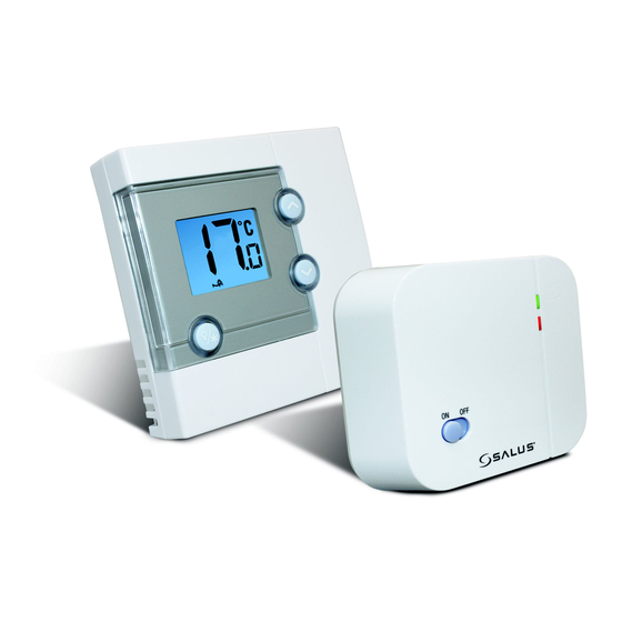
- Page 4 INTRODUCTION The RT300RF from SALUS Controls is a stylish and accurate digital thermostat with a large, easy to read Liquid Crystal Display (LCD). This thermostat has been specifically designed to be used for both Volt Free and AC heating applications, can replace most common residential thermostats and is designed to be used with electric, gas or oil heating control systems.
-
Page 5: Installation
Control Centre. The back plate can be mounted directly to the wall surface. The ideal position to locate the RT300RF Control Centre is about 1.5m above floor level. It should be mounted in a location where the thermostat is accessible, reasonably lit and free from extremes of temperature and draughts. - Page 6 The RT300RF Receiver should be mounted in a suitable location that is both accessible for the connection of mains and control wiring, and allows good reception of the RF signal. The Receiver needs a 230V AC mains supply to operate, and this should be fused appropriately (13A max.). The Receiver should be mounted in a location where it will not come into contact with water, moisture or condensation.
- Page 7 • Receiver unit should have a permanent 230V AC main supply • Confirm that the Boiler has an external thermostat loop and is configured for 230V switching • If the boiler has two terminals for the thermostat, remove the link from the boiler RT300RF INSTRUCTION MANUAL...
- Page 8 • Receiver unit should have a permanent 230V AC main supply • Confirm that the Boiler has an external thermostat loop and is NOT configured for 230V switching • If the boiler has two terminals for the thermostat, remove the link from the boiler RT300RF INSTRUCTION MANUAL...
- Page 9 DIP switch on the Receiver. NOTE: The Reset button must be pressed after changing jumper positions. The Reset button is accessible behind the small hinged door on the front right hand side of the Control Centre. RT300RF INSTRUCTION MANUAL...
-
Page 10: Rf Address Code Setting
5 DIP switch levers on the DIP switch bank located on the back of the receiver (the levers are numbered 1 to 5 from bottom to top, as shown in the picture below), and then make a note of the setting of each switch: RT300RF INSTRUCTION MANUAL... - Page 11 Please make sure that you keep any of the jumper caps you remove in a safe place, in case you later need to change the RF address setting again. You must press RESET on the Control Centre after making any changes to the RF address code settings. RT300RF INSTRUCTION MANUAL...
-
Page 12: Testing The Rf Transmission
(red LED lit). If this isn’t the problem you can also alter the RF address code by following the ‘RF Address Code Setting’ section of this manual, and then repeat steps 1 to 5 (note that the RESET button on the Control Centre should be pressed after altering the address code). RT300RF INSTRUCTION MANUAL... - Page 13 Once all the RT300RF units have been installed, if one unit then seems to function abnormally, try changing the RF address code of that unit’s Control Centre and its corresponding Receiver, making sure that the new RF address code is different to all others in the installation.
-
Page 14: After Installation
AFTER INSTALLATION The following table shows the settings of the RT300RF digital thermostat after Power on, or after RESET is pressed: Function Status After Reset or Power On Operation Mode Normal mode Room Temperature 22.0 °C, updated within 5 seconds Set Point Temperature 20.0 °C... - Page 15 USER INTERFACE AND CONTROLS The status and operation of the RT300RF is clearly shown on the large backlit Liquid Crystal Display (LCD). This display allows the user a clear indication of the current room temperature, and the status of the heating system.
-
Page 16: Operation
The set point temperature will flash to indicate that it can be changed: The temperature will be changed in 0.5°C steps per key press. The RT300RF will return to Normal mode if no keys are pressed for more than four seconds. -
Page 17: Frost Protection
Please be aware that the Frost Protection mode operates as an additional protection feature but should not be used in place of a correctly installed frost thermostat, which is required to override all other controls in the system. The backlight will remain illuminated for approximately 5 seconds. RT300RF INSTRUCTION MANUAL... -
Page 18: Reset Button
Pressing this button will delete any previously entered settings. Sleep Mode By pressing both the UP and DOWN keys together, the RT300RF will enter SLEEP mode. In this mode, all the RT300RF functions will be paused to save battery power. While in SLEEP mode: •... - Page 19 - you won’t have to adjust the thermostat further, as adjustment above this setting will waste energy - a 1 °C increase in temperature is equal to 3% of your heating costs. RT300RF INSTRUCTION MANUAL...
-
Page 20: Maintenance
SALUS Controls sole liability for breach of this warranty will be (at its option) to repair or replace the defective product. -
Page 21: Product Specification
Switch Rating Switching Voltage: 0 - 230V AC / 50Hz Switching Current: 16A resistive, 5A inductive Protection Rating: IP30 Environment Operating Temperature: 0 ºC to + 40 ºC Storage Temperature: - 10 ºC to + 60 ºC RT300RF INSTRUCTION MANUAL... - Page 22 SALUS Controls sole liability for breach of this warranty will be (at its option) to repair or replace the defective product.
- Page 23 RT300RF INSTRUCTION MANUAL...
- Page 24 Email: sales@salus-tech.com Tel: 01226 323961 Sales Email: tech@salus-tech.com Tel: 01226 323961 Technical SALUS Controls plc, SALUS House, Dodworth Business Park South, Whinby Road, Dodworth, Barnsley S75 3SP...
Need help?
Do you have a question about the RT300RF and is the answer not in the manual?
Questions and answers
My room temperature is higher then the temp set on the thermostat but my boiler is still kicking in on the set time regardless of the temperature
The Salus RT300RF thermostat may be activating the boiler even when the room temperature is higher than the set temperature due to the following reasons:
1. Time Switch or Programmer Setting: The thermostat only works if the time switch or programmer is on. If the time switch is set to always on, the thermostat may activate the boiler even when not needed.
2. Faulty or Stuck Relay: The receiver unit may have a stuck relay, causing the boiler to remain on even when the thermostat does not call for heat.
3. Incorrect Thermostat Placement: If the thermostat is placed near a heat source or in a cold spot, it may misread the temperature and activate the boiler unnecessarily.
4. Signal Transmission Delay: The thermostat transmits signals at intervals, and a delay in communication between the thermostat and receiver may cause incorrect activation.
5. Reset or Reconfiguration Needed: If there was a recent change in settings or jumper positions, the reset button may need to be pressed for proper operation.
Checking these factors can help diagnose and resolve the issue.
This answer is automatically generated