Eaton VoCALL 16 Installation And Operation Manual
Emergency voice communication system
Hide thumbs
Also See for VoCALL 16:
- Installation and operation manual (88 pages) ,
- Installation and operation manual (116 pages)

Related Manuals for Eaton VoCALL 16


Summary of Contents for Eaton VoCALL 16
- Page 1 VoCALL 16 Emergency Voice Communication System Network Configuration Installation and operation manual...
-
Page 2: Table Of Contents
12.3 Example installation .........82 INStALLAtIoN ANd opErAtIoN mANuAL 25-16760-A January 2020 www.eaton.com... - Page 3 APPENDIX 5 – Checklist ........145 APPENDIX 6 – Menu structure - Master panel ..... . .146 INStALLAtIoN ANd opErAtIoN mANuAL 25-16760-A January 2020 www.eaton.com...
- Page 4 Contents APPENDIX 7 – Eaton CCOE Cybersecurity Recommendations ..147 APPENDIX 8 – Planning notes – Network ......149...
-
Page 5: Document Update Notes
THIS DOCUMENT SHALL NOT BECOME PART OF OR MODIFY ANY CONTRACT BETWEEN THE PARTIES. In no event will Eaton be responsible to the purchaser or user in contract, in tort (including negligence), strict liability or other-wise for any special, indirect, incidental... -
Page 6: Support Services
4. Support Services 4. SUPPORT SERVICES The goal of Eaton is to ensure your greatest possible satisfaction with the operation of our products. We are dedicated to provide fast, friendly, and accurate assistance. Website Visit the Eaton website to find product information. You can also find information on local distributors or Eaton sales offices. -
Page 7: Important Safety Information
If the units are distributed around a site it is essential all units are on the same mains phase, as they are classified tEN 230V, powering from different phases can mean a 440V potential can be present in a unit during a major fault incident. INStALLAtIoN ANd opErAtIoN mANuAL 25-16760-A January 2020 www.eaton.com... - Page 8 Indoor use only. do not expose this unit to rain or moisture. CAutIoN VoCALL 16 must only be installed by certified Eaton personnel i.e. an Eaton Customer Service Engineer or certified installer. In case of violating these requirements the warranty provided will not apply and EAtoN will not be held legally accountable.
-
Page 9: Receipt/Unpacking
Remove all packing material from the unit. Check the unit for any signs of shipping damage. If damage is found after unpacking, report it to the Freight Company and EATON. Retain the packaging materials for the carrier to review. Storage It is recommended that the unit should be stored in its original shipping box/crate until it is to be installed. -
Page 10: About This Manual
VoCALL 16 emergency voice communication system (EVCS) and personnel who are responsible for operating the system. This manual covers operation of VoCALL 16 devices in network mode i.e. more than one panel connected together are part of installation. -
Page 11: Overview
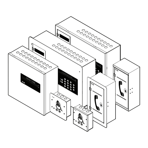
9. Overview 9. Overview 9.1 Introduction VoCALL 16 EVCS is a high specification, digital, loop –wired, fully addressable, monitored, and secure bi-directional communication system compliant with BS5839-9:2011 (abb. Pt9). VoCALL 16 range of products comprises of two types of devices: Panels: Main panel (MX16), Network panel (NX16) •... - Page 12 *BS 5839-9: 2011 Fire detection and fire alarm systems for buildings. Code of practice for the design, installation, commissioning and maintenance of emergency voice communication systems. Cabling to comply with local regulations and codes of practice. ote: INStALLAtIoN ANd opErAtIoN mANuAL 25-16760-A January 2020 www.eaton.com...
-
Page 13: Main Panel - All Variants
9.2 Main Panel – all variants Figure 1. mX16 and mX16 –SSC MX16 VoCALL 16 Main panel MX16-SSC VoCALL 16 Main panel Stainless front pack, Flush mounting MX16-BEZ VoCALL 16 Main panel, semi-flush frame bezel Dimension H 355 X W 488 X D 155 mm Stainless Front Dimension H 390 X W 522 X D 2.5 mm... -
Page 14: Network Panel
Fault Indications Audio visual - Network/Communication, Sensors, Health Security Logging of physical access to panel Memory 4 GB SDHC card Battery 2 x 12V @ 12Ah SLA battery. Yuasa NP12-12 (Recommended, Not supplied) INStALLAtIoN ANd opErAtIoN mANuAL 25-16760-A January 2020 www.eaton.com... -
Page 15: Type A Outstation - All Variants
Fault Indications Audio visual - Network/Communication, Sensors Security Handset behind latched door ote: TA16-BEZ, TA16-BEZ-SS are available as separate bezel units. Flush mounting: TA16-RS + TA16-BEZ (Bezel). TA16-BEZ should be procured separately. INStALLAtIoN ANd opErAtIoN mANuAL 25-16760-A January 2020 www.eaton.com... -
Page 16: Type B Outstation - All Variants
21V to 27.6V (Nominal 24V) DC - Loop driven Power Consumption Active - 0.65 Watts Standby - 0.52 Watts Indications Audio visual - Network/Communication, Sensors , Braille symbols on buttons Security Not applicable. User interaction using buttons on front. INStALLAtIoN ANd opErAtIoN mANuAL 25-16760-A January 2020 www.eaton.com... -
Page 17: Features
Studies have shown this approach can support up to a 75% reduction in cable installation costs. i.e. cables, tray, fixings, conduit and most importantly, time. Simple and easy installation: VoCALL 16 Panel can support up to 16 loop • powered Outstations. Outstations can be of variant Type A/B. Pictorial installation instructions are supplied with all units. - Page 18 9. Overview user configuration: VoCALL 16 facilitates a maximum of 10 user login / profiles • to be created per panel. Each user’s profile can be configured independently allowing system administrator flexibility to support the needs of most demanding applications. For details, refer to Section 11.
-
Page 19: Installation
10. Installation 10. Installation 10.1 Placement guidelines The VoCALL 16 system is intended for indoor usage. Outstations should not be installed outdoors unless an additional IP65, or better housing, is used and cables are installed to prevent the ingress of moisture. -
Page 20: Mounting Instructions
3. To lift top cover, remove the screws as shown in step A. Lift the cover from bottom and push back to disengage clips. Disconnect ground cable for easy operation. Figure 6. Steps to open top cover INStALLAtIoN ANd opErAtIoN mANuAL 25-16760-A January 2020 www.eaton.com... - Page 21 4 (# 2 core wire), 2 (# 4 core wire) Panel communication 4 (# 2 core wire), 2 (# 4 core wire) Relay – In Use, Fault Power supply Input – Enable (if required) Ethernet INStALLAtIoN ANd opErAtIoN mANuAL 25-16760-A January 2020 www.eaton.com...
- Page 22 195mm 200mm 39mm 281mm 27mm 248mm Mounting Hole Rear Knockout Figure 9. Front view of panel with the hinged user interface removed. only for clarity of instructions. do Not dEtACH tHE uNIt. INStALLAtIoN ANd opErAtIoN mANuAL 25-16760-A January 2020 www.eaton.com...
- Page 23 Figure 11. Wiring Connections to be done by installer. Knockouts shown used are for illustration purposes only. 7 . Battery: VoCALL 16 MX panel requires 2 x 12V @ 12Ah sealed lead acid batteries to provide backup power in the event of mains failure. Install the batteries after securely mounting the panel.
- Page 24 Replace the supplied front cover of the MX panel with SS front pack bezel. Figure 12. mX16-SSC unit. replace the mX16 front cover with the SS panel front to enable flush mounting Figure 13. mX16 flush mount unit ready for installation INStALLAtIoN ANd opErAtIoN mANuAL 25-16760-A January 2020 www.eaton.com...
- Page 25 10. Installation NX16 1. Take the unit out of the packing material. 2. Check the content against checklist provided in Appendix 1. User Interface Figure 14. NX16 panel INStALLAtIoN ANd opErAtIoN mANuAL 25-16760-A January 2020 www.eaton.com...
- Page 26 To lift top cover – Open screws. Lift the cover from bottom and push back to disengage clips. Disconnect ground cable for easy operation. Figure 15. Steps to open top cover Ground Cable. Disconnect for easy operation. Figure 16. View of panel with top cover detached INStALLAtIoN ANd opErAtIoN mANuAL 25-16760-A January 2020 www.eaton.com...
- Page 27 Figure 18. Wiring Connections to be done by installer. Knockouts shown used are for illustration purposes only. Do not remove more knockouts than required. Use appropriate glands while ote: wiring. Recommended glands: AMP – TE Connectivity (178771-3) INStALLAtIoN ANd opErAtIoN mANuAL 25-16760-A January 2020 www.eaton.com...
- Page 28 5. Wire the unit. Refer to section “10.5 Wiring details” for details. 6. Battery: VoCALL 16 NX panel requires 2 x 12V @ 12Ah sealed lead acid batteries (not supplied) to provide to provide backup power in event of mains failure.
- Page 29 4. PCB is located underneath the handset resting plate. To wire the unit, open and remove the plate from the unit. Disconnect ground cable for easy operation. Figure 21. open screws to remove phone plate INStALLAtIoN ANd opErAtIoN mANuAL 25-16760-A January 2020 www.eaton.com...
- Page 30 Figure 22. Ground cable connection. disconnect for ease of use. 5. Knockouts are provided at the bottom of box. Double tag knockouts are provided for easy removal. Remove knockouts as required by the application. Figure 23. double tag knockouts INStALLAtIoN ANd opErAtIoN mANuAL 25-16760-A January 2020 www.eaton.com...
- Page 31 Loop out To be done by installer Refer Figure 47 OS OUT (PORT B) OS IN (PORT A) OS TYPE A PCB HANDSET CRADLE Figure 25. Connector placement on type A outstation INStALLAtIoN ANd opErAtIoN mANuAL 25-16760-A January 2020 www.eaton.com...
- Page 32 8. Assemble the unit. Reconnect ground cable before closing the unit. Figure 26. type A unit ready to be mounted Flush mount Version: A frame type bezel is available as separate unit to enable flush mounting. 114mm Figure 27. Flush mounting procedure INStALLAtIoN ANd opErAtIoN mANuAL 25-16760-A January 2020 www.eaton.com...
- Page 33 3. Remove screws to open the unit. PCB is mounted underneath the cover. Figure 28. type B unit 4. Disconnect ground cable for easy installation. Figure 29. remove ground cable for easy installation INStALLAtIoN ANd opErAtIoN mANuAL 25-16760-A January 2020 www.eaton.com...
- Page 34 To be done by installer Refer Figure 46 to Figure 48 OS OUT (PORT B) OS IN (PORT A) SPEAKER OS TYPE B PCB Figure 31. type B oS pCB connector placement INStALLAtIoN ANd opErAtIoN mANuAL 25-16760-A January 2020 www.eaton.com...
- Page 35 Figure 32. type B unit ready to be installed Wall mount and flush mount units for Type B outstations are available as ote: separate products. 56mm Figure 33. type B - flush mounted INStALLAtIoN ANd opErAtIoN mANuAL 25-16760-A January 2020 www.eaton.com...
-
Page 36: Installation Architecture
10. Installation 10.3 Installation architecture VoCALL 16 has been designed to enable simple installation and aid ease of expansion of an installed system. VoCALL 16 offers features that are designed to support different installation types and requirements. The system can be configured in two forms: 1. - Page 37 Maximum distance between Panel and Outstation – 200m Maximum distance between two Outstations – 200m Maximum loop length - Outstation: 2 Km FP200, 200m OS 2 OS 1 Main Panel OS 16 OS 15 Figure 34. topology - Standalone INStALLAtIoN ANd opErAtIoN mANuAL 25-16760-A January 2020 www.eaton.com...
- Page 38 FP200, 200m max. OS 1 OS 1 OS 16 OS 16 FP200, 200m max. FP200, 200m max. FP200, 300m max. VoCALL MX16 (MASTER Panel) VoCALL NX16 (Panel 2) Figure 36. Network topology - System INStALLAtIoN ANd opErAtIoN mANuAL 25-16760-A January 2020 www.eaton.com...
- Page 39 Figure 37. (left) High rise building example Figure 38. (below) Campus type buildings example This manual focuses on network installation. Detailed steps for standalone ote: configuration are covered in manual ‘EVCS standalone manual’. INStALLAtIoN ANd opErAtIoN mANuAL 25-16760-A January 2020 www.eaton.com...
-
Page 40: Cabling Requirements
Outstations. Use screened cabling throughout the installation. Ensure screen wiring is securely bonded to the earth/shield terminals provided. mains wiring: VoCALL 16 requires a mains supply exclusive to the panel that uses fixed three-core wiring (between 0.75mm and 2.5mm ) which is fed from a double pole isolating fuse connection unit, fused at 3A. -
Page 41: Wiring Details
The batteries are connected in series and their output is connected to the PSU, at the designated connector. The wiring harness for connecting batteries is provided with the unit. Two harnesses are provided for: 1. PSU to Battery connection. 2. Battery series connection. INStALLAtIoN ANd opErAtIoN mANuAL 25-16760-A January 2020 www.eaton.com... - Page 42 TO BATTERY 1 TO BATTERY 2 130 mm Figure 41. Battery to battery connection diagram Figure 42. mX16 battery connections Thermistor should be placed near batteries ote: ote: Recommended battery: 2x Yuasa NP12-12 INStALLAtIoN ANd opErAtIoN mANuAL 25-16760-A January 2020 www.eaton.com...
- Page 43 24 hours in standby mode. After this period, battery would have sufficient capacity to support a call continuously for more than 3 hours. Batteries would require 24hrs to charge back to full capacity. INStALLAtIoN ANd opErAtIoN mANuAL 25-16760-A January 2020 www.eaton.com...
- Page 44 This connection is already wired on the supplied unit and is shown for information only. The power supply unit provides 24V DC output required to power up the system. VoCALL 16 communicates with and monitors the power supply for its health status.
- Page 45 PANEL OUT (PORT 1) PANEL IN (PORT 2) ETHERNET OS OUT (PORT A) OS IN (PORT B) MAIN BOARD CRADLE HANDSET Figure 47. outstation wiring – power and data cable detail connections INStALLAtIoN ANd opErAtIoN mANuAL 25-16760-A January 2020 www.eaton.com...
- Page 46 Panel 20 Panel 19 Panel 18 Figure 49. daisy chain loop for panel wiring Panel 2 Panel 3 Panel 4 Panel 5 Panel 6 Panel 7 Panel 8 Panel 9 Panel 10 INStALLAtIoN ANd opErAtIoN mANuAL 25-16760-A January 2020 www.eaton.com...
- Page 47 Figure 50. panel port - port connections Enhanced FP200 2/4 RX– RX– TX– TX– UP TO 300 m SHLD SHLD Up to 24 panels can be SHLD SHLD Figure 51. panel port - port wiring – detail connections INStALLAtIoN ANd opErAtIoN mANuAL 25-16760-A January 2020 www.eaton.com...
- Page 48 Any active call on the network is not impacted by application the input signal. Enhanced FP200 2 Core; 1.5 sq mm To NON-EVCS UP TO 10m SYSTEM Relay Contacts Shield terminal can be terminated at screw available near the connector Figure 52. relay/Input wiring connections INStALLAtIoN ANd opErAtIoN mANuAL 25-16760-A January 2020 www.eaton.com...
- Page 49 To be reconnected by installer MX / NX, OS Communication - Panel To be done by installer Refer to Figure 46 to Figure 51 Ethernet To be connected as needed Refer to page 116 INStALLAtIoN ANd opErAtIoN mANuAL 25-16760-A January 2020 www.eaton.com...
-
Page 50: Commissioning
Network panel (NX16) is configured to operate in network mode as out of factory configuration. For network installation, Main panel needs to be converted from standalone mode to network mode by an EATON trained personnel. All main panels that are part of installation are required to undergo the change. - Page 51 Type #S. No. of menu item to reach it faster. • Example: To reach item 6 on menu, press ‘6’, then press ‘Accept’ using keypad. In instructions following this section, #No. [# menu number] are mentioned ote: along with the steps. INStALLAtIoN ANd opErAtIoN mANuAL 25-16760-A January 2020 www.eaton.com...
-
Page 52: Configuration - Network System
**** Last Login HH:MM DD/MM/YY As an enhanced security measure, the system provides the information ote: of last login attempt. ote: It is required to change the default pin after first login. INStALLAtIoN ANd opErAtIoN mANuAL 25-16760-A January 2020 www.eaton.com... - Page 53 4. Select a panel as mAStEr panel. Steps to select a MX16 panel as MASTER: a. Login as Engineer 2 b. Select option ‘Install’ [#9]. c. Select option ‘System Settings’. d. Tick the option ‘master panel’. INStALLAtIoN ANd opErAtIoN mANuAL 25-16760-A January 2020 www.eaton.com...
- Page 54 2 Names 3 Outstation Learn 4 Update Software 5 Factory Defaults For #3 outstation Learn option to appear in this menu, a valid panel ID ote: muSt be set in System Settings. INStALLAtIoN ANd opErAtIoN mANuAL 25-16760-A January 2020 www.eaton.com...
- Page 55 / delete them. Two options are added as sub menu under ‘Install’ once learn is successful - ote: Webserver, Config. Backup / Restore. INStALLAtIoN ANd opErAtIoN mANuAL 25-16760-A January 2020 www.eaton.com...
- Page 56 PANEL ID parameter or no value has been set for the parameter. d. Outstation learn required : Auto-addressing of connected Outstations need to be performed. e. System learn required : System learn is needed for bringing panel in the network. INStALLAtIoN ANd opErAtIoN mANuAL 25-16760-A January 2020 www.eaton.com...
- Page 57 On selecting yes, the MASTER panel can access all features of selected panel remotely. Nomenclature of ‘rEmotE’ panel is used to denote the panel accessed remotely. INStALLAtIoN ANd opErAtIoN mANuAL 25-16760-A January 2020 www.eaton.com...
- Page 58 1 System Settings Enable Input 2 Names System Panel Enable Outstation Learn Update Software Factory Defaults 9. Repeat above procedure for all panels till all faults related to c) and d) are resolved. INStALLAtIoN ANd opErAtIoN mANuAL 25-16760-A January 2020 www.eaton.com...
- Page 59 Master panel gets notification when top cover of any panel (MX / NX) is ote: opened as an added security measure. This feature can be used to verify the ID assigned to NX panel. INStALLAtIoN ANd opErAtIoN mANuAL 25-16760-A January 2020 www.eaton.com...
- Page 60 Date format selected will be circulated to all panels in the network. ote: Key Bleep VoCALL 16 system provides facility of audible feedback on pressing any key. A bleep is heard if key press is registered. Select ‘Key Bleep’ to enable or disable bleep sound any on key press.
- Page 61 3. Press ‘down’ to select ‘Set time’. Press ‘Accept’ 4. Panel will give a confirmation message if input is saved. 5. Press ‘Back’ to go back up one menu. User will not be able to enter incorrect values. ote: INStALLAtIoN ANd opErAtIoN mANuAL 25-16760-A January 2020 www.eaton.com...
- Page 62 Event log – Set date and Set time are stored in event log. All logs would use the time and date information set by user. ote: Time, Date, Daylight saving are common for entire system and are circulated across the network from the MASTER panel. INStALLAtIoN ANd opErAtIoN mANuAL 25-16760-A January 2020 www.eaton.com...
-
Page 63: User Configuration - Definitions Of Access Levels
11.2 User Configuration - Definitions of Access levels Post successful completion of system learn, next step is to define user settings and details. In accordance with BS 5839-9:2011 standard, VoCALL 16 product range provides following access levels for appropriate usage of the system. - Page 64 Webserver Enable (only for Engineer2 login) ote: Accepting system fault by ‘ENGINEER’ would clear the fault from current faults log. It is expected that faults are accepted by ‘ENGINEER’ only after they have been corrected. INStALLAtIoN ANd opErAtIoN mANuAL 25-16760-A January 2020 www.eaton.com...
-
Page 65: Configuring Access Profiles
The person responsible for maintaining the system is responsible for maintaining the compliance with local regulations and standards. Any deviation from the default profiles should be agreed by all parties and recorded in the maintenance, commissioning and hand over documents. INStALLAtIoN ANd opErAtIoN mANuAL 25-16760-A January 2020 www.eaton.com... - Page 66 5. To activate/de-activate the user profile select on ‘Enabled’. MANAGER 2 (4-5) 1 Change PIN 2 Name 3 Access Rights 4 Enabled 5 System PIN 6. The profile enabled will have default rights as described in Section 11.2. INStALLAtIoN ANd opErAtIoN mANuAL 25-16760-A January 2020 www.eaton.com...
- Page 67 11. Commissioning 2. System user VoCALL 16 provides the option to have uniform user configuration across all the panels of the network by selecting the user as a ‘System User’. User name, access rights, PIN for system user are same for all panels on the network. System user’s configuration can only be modified from the MASTER panel.
- Page 68 As a best practice to enhance security, ensure minimum rights required are enabled for any user of the system. 4. Configuring access rights VoCALL 16 facilitates configuring access profile individually as per user’s requirement. Steps to configure any profile: 1. Login as ‘ENGINEEr 2’.
- Page 69 8. Max character length for the name is 16 characters. 9. Default names would be considered if names are not updated. Ensure to change the name to reflect the name of person/position responsible ote: for operation or maintenance of the system. INStALLAtIoN ANd opErAtIoN mANuAL 25-16760-A January 2020 www.eaton.com...
- Page 70 2. To share profile details and PIN in the same communication (email, message). A user of the system can also change its own PIN later, if it is provided with required permission. Steps to change PIN for own profile: 1. Login to access profile INStALLAtIoN ANd opErAtIoN mANuAL 25-16760-A January 2020 www.eaton.com...
- Page 71 3. Enter new pin and confirm the pin change. 7 . disable pIN The VoCALL 16 system has the ability to disable PIN input for using the display interface, however, this is not recommended and should be recorded as a deviation.
- Page 72 12 Test 3. Go to option ‘max Login Attempts’ 4. Select the number. Range 1 – 10. Manage Users (11-13) MANAGER 2 MANAGER 3 ENGINEER 1 ENGINEER 2 PIN Required Max. Login Attempts INStALLAtIoN ANd opErAtIoN mANuAL 25-16760-A January 2020 www.eaton.com...
- Page 73 Panel ID is assigned by Installer. It would not change when changing MASTER panel location. As Panel ID is used for dialing details, there is no change in dialing number. INStALLAtIoN ANd opErAtIoN mANuAL 25-16760-A January 2020 www.eaton.com...
-
Page 74: Communication
12. Communication 12.1 Calling Operation Multiple types of calls are possible on VoCALL 16 – call between any panel and an Outstation; call between two panels. Call between two Outstations is not allowed. Procedure to initiate and receive a call is described below. - Page 75 Example: To Call Outstation #5 connected to Panel #1, dial – 0105. To dial panel #3 from panel #2 dial -0300. Accept Speaker Out Down Listen In Hold Call Back Cancel Call Accept Call INStALLAtIoN ANd opErAtIoN mANuAL 25-16760-A January 2020 www.eaton.com...
- Page 76 - either incoming or hold calls, then active call is ended by pressing the ‘End Call’ key on panel. Next call can then be selected from the list using ‘ACCEpt Call’ key. INStALLAtIoN ANd opErAtIoN mANuAL 25-16760-A January 2020 www.eaton.com...
- Page 77 B outstation. Dial the number of the outstation and press ‘Loud-speak’ to start the call. Press ‘Cancel’ or put the handset down to end the call. INStALLAtIoN ANd opErAtIoN mANuAL 25-16760-A January 2020 www.eaton.com...
- Page 78 5. Save the settings. 6. Repeat above steps for Panel ID #3, #4 Above would allow panels 2 , 3, 4 to be disabled together on application of external trigger on panel 4. INStALLAtIoN ANd opErAtIoN mANuAL 25-16760-A January 2020 www.eaton.com...
-
Page 79: Calling Rules
YY = 00 (for panel) or Outstation address (01 to 16) 4. Nomenclature: a. Local call: Call between panel and outstation directly connected to it. b. Network call: Call between panel and an outstation which is not directly connected to it. INStALLAtIoN ANd opErAtIoN mANuAL 25-16760-A January 2020 www.eaton.com... - Page 80 Main panel (MX16) can dial any other MX16 by dialing its number. b. RS485 communication loop is controlled by the panel initiating the call. c. Panel initiating the call only can put the call on hold. INStALLAtIoN ANd opErAtIoN mANuAL 25-16760-A January 2020 www.eaton.com...
- Page 81 (NX16) panels. c. Outstation calls are always visible to its local panel. 11. Disablement of calls on network / panel / group of panels. VoCALL 16 provides option to disable calls on a panel and connected outstations, partial or complete network.
-
Page 82: Example Installation
12.3 Example installation The section describes the considerations to be taken care of while configuring functionality of VoCALL 16 for a network with an example site installation. The section would cover possible calling scenarios and guidelines for routing of calls across the network. - Page 83 Call is picked by Panel ID #8. CAN communication loop of panel 08 occupied. 01 – MX 02 – MX 03 – MX 04 – MX 05 – NX 06 – NX 07 – MX 08 – MX INStALLAtIoN ANd opErAtIoN mANuAL 25-16760-A January 2020 www.eaton.com...
- Page 84 Any subsequent call by the Outstations on the same loop will be visible to Panel #8 only. 01 – MX 02 – MX 03 – MX 04 – MX 05 – NX 06 – NX 07 – MX 08 – MX INStALLAtIoN ANd opErAtIoN mANuAL 25-16760-A January 2020 www.eaton.com...
- Page 85 02 – MX 03 – MX 04 – MX 05 – NX 06 – NX 07 – MX 08 – MX Any subsequent calls from Outstations connected to Panel #5 are visible only to INStALLAtIoN ANd opErAtIoN mANuAL 25-16760-A January 2020 www.eaton.com...
- Page 86 07 – MX 08 – MX Call by Outstation: 0205 can be collected by Panel #2 or Panel #8. Any calls from Outstations connected to Panel #8 can only be collected by Panel #8. INStALLAtIoN ANd opErAtIoN mANuAL 25-16760-A January 2020 www.eaton.com...
- Page 87 If a panel chooses to answer its local call, indications of other calls will be visible to all the panels. 01 – MX 02 – MX 03 – MX 04 – MX 05 – NX 06 – NX 07 – MX 08 – MX INStALLAtIoN ANd opErAtIoN mANuAL 25-16760-A January 2020 www.eaton.com...
- Page 88 Panel ID #8 has kept call of 0804 on hold to answer call from 0806. 01 – MX 02 – MX 03 – MX 04 – MX 05 – NX 06 – NX 07 – MX 08 – MX INStALLAtIoN ANd opErAtIoN mANuAL 25-16760-A January 2020 www.eaton.com...
- Page 89 The call from 0105 is visible to Panel ID #1 only. Panel can see the list of all calls (incoming, on hold) by pressing ‘Back’ button ote: when keypad sign ( ) is visible on lower left portion of the screen. INStALLAtIoN ANd opErAtIoN mANuAL 25-16760-A January 2020 www.eaton.com...
- Page 90 – CAN loop of OS 0804, CAN loop of OS 0503, its own CAN loop and RS485 communication loop. 01 – MX 02 – MX 03 – MX 04 – MX 05 – NX 06 – NX 07 – MX 08 – MX INStALLAtIoN ANd opErAtIoN mANuAL 25-16760-A January 2020 www.eaton.com...
- Page 91 Panel ID #8 is calling its local Outstation 0803. 01 – MX 02 – MX 03 – MX 04 – MX 05 – NX 06 – NX 07 – MX 08 – MX INStALLAtIoN ANd opErAtIoN mANuAL 25-16760-A January 2020 www.eaton.com...
- Page 92 Outstation on the network as RS485 communication loop is currently under control of Panel ID #8. On dialing an Outstation that is on call with some other panel a busy tone will be heard. INStALLAtIoN ANd opErAtIoN mANuAL 25-16760-A January 2020 www.eaton.com...
- Page 93 ‘Handset not available’ message is displayed on panel LCD screen. 7: panel to panel calls VoCALL 16 allows calls between two main panels. The panel initiating the call controls the associated communication loops. Only one panel to panel call is allowed at a time.
- Page 94 Outstation. 01 – MX 02 – MX 03 – MX 04 – MX 05 – NX 06 – NX 07 – MX 08 – MX INStALLAtIoN ANd opErAtIoN mANuAL 25-16760-A January 2020 www.eaton.com...
- Page 95 Panel ID #7 can put its active call on hold to answer call from 0205. 01 – MX 02 – MX 03 – MX 04 – MX 05 – NX 06 – NX 07 – MX 08 – MX INStALLAtIoN ANd opErAtIoN mANuAL 25-16760-A January 2020 www.eaton.com...
- Page 96 08 – MX Fault tolerant design VoCALL 16 is tolerant of a single fault on any communication loop. Calls are not impacted by single fault in the communication loop. It can also recover from simultaneous single faults on different communication loops. In case of multiple faults, subset of network not impacted by fault continues to operate as intended.
- Page 97 06 – NX 07 – MX 08 – MX Routing of calls should be done sensibly based on site architecture and panel type. Please consult trained professionals to verify the routing strategy. INStALLAtIoN ANd opErAtIoN mANuAL 25-16760-A January 2020 www.eaton.com...
- Page 98 12. Communication 9. Call scenarios with panel disabled VoCALL 16 provides an option to put a panel in disabled condition. When a panel is disabled it will not accept any call from the network. Its connected Outstations are not allowed to make or receive calls.
- Page 99 At the end of call the panel relinquishes the control. 01 – MX 02 – MX 03 – MX 04 – MX 05 – NX 06 – NX 07 – MX 08 – MX INStALLAtIoN ANd opErAtIoN mANuAL 25-16760-A January 2020 www.eaton.com...
-
Page 100: Configuration
13. Configuration 13. Configuration 13.1 Webserver VoCALL 16 provides an ethernet based application (‘Webserver’) aiding configuration of parameters and monitoring of installation. System should be in learned / addressed state for the utility to be used. ote: Using webserver for editing parameters puts the system in engineering mode. - Page 101 3. Left click on Ethernet and click on properties. 4. Select Internet Protocol Version 4 (TCP/IPv4). Click on properties. 5. Input below values in the settings. Click ok. a. IP address: 192.168.1.2 b. Subnet mask: 255.255.255.0 c. Default gateway: 192.168.1.1 INStALLAtIoN ANd opErAtIoN mANuAL 25-16760-A January 2020 www.eaton.com...
- Page 102 Step 7 mentioned in above steps is crucial to access webserver. ote: ote: Webserver session will time out for the user after a period of 15 mins of inactivity. INStALLAtIoN ANd opErAtIoN mANuAL 25-16760-A January 2020 www.eaton.com...
- Page 103 2. Language selection – English language is supported in current version 3. Option to change password of current user logged in 4. Help button – provides the link to download manual 5. Date and time of the panel 6. Logout button INStALLAtIoN ANd opErAtIoN mANuAL 25-16760-A January 2020 www.eaton.com...
- Page 104 01-16 – Outstation handset status. Clicking on the row directs to detail information (read only) of the panel and its connected outstations. Clicking on ‘Active Faults’ directs to the list of faults present on panel. INStALLAtIoN ANd opErAtIoN mANuAL 25-16760-A January 2020 www.eaton.com...
- Page 105 The log page provides list of active faults, log of past faults recorded on the panel, call logs, event log and of the selected panel. Up to 10 log entries are displayed per page. INStALLAtIoN ANd opErAtIoN mANuAL 25-16760-A January 2020 www.eaton.com...
- Page 106 13. Configuration INStALLAtIoN ANd opErAtIoN mANuAL 25-16760-A January 2020 www.eaton.com...
- Page 107 LCD will also be prohibited. Navigating to any other page will make system exit the ‘Engineering Mode’. time / date ote: Invalid entries will not be allowed. ote: Press tick box to save the settings for each parameter individually. INStALLAtIoN ANd opErAtIoN mANuAL 25-16760-A January 2020 www.eaton.com...
- Page 108 The page will show the list of all panels connected on the system. Select the panel (by selecting the tick box), to whom the calls should be allowed / routed to. INStALLAtIoN ANd opErAtIoN mANuAL 25-16760-A January 2020 www.eaton.com...
- Page 109 Webserver can also be used during operation for monitoring the status of the system - calls, faults, logs. Figure 58. oS 02 calling panel Figure 59. Call to oS 02 kept on hold INStALLAtIoN ANd opErAtIoN mANuAL 25-16760-A January 2020 www.eaton.com...
- Page 110 Certain functions eg – LCD users configuration, system upgrade are available ote: only via LCD interface. ote: Use of LCD sub-menu under option ‘Install’ is not permitted while webserver is connected. INStALLAtIoN ANd opErAtIoN mANuAL 25-16760-A January 2020 www.eaton.com...
-
Page 111: Saving Configuration
13. Configuration 13.2 Saving Configuration VoCALL 16 enables saving configuration parameters of a system or a particular panel as a record. Configuration files are stored on SD card. ote: Feature to save configuration file is available on LCD only. 1. Login as ‘ENGINEEr 2’. - Page 112 Enable input settings Call routing settings xi. Outstation Name xii. No of Outstations xiii. Type of Outstations b. Display settings Brightness Contrast iii. Language Date Format Key Bleep status c. User settings INStALLAtIoN ANd opErAtIoN mANuAL 25-16760-A January 2020 www.eaton.com...
-
Page 113: Factory Defaults
5 Web Server Users 6 Restore 4. Select the parameters to be restored to default value. 5. Go to ‘restore’. Press ‘Accept’ 6. Panel will undergo power-cycle after parameters are restored to default values. INStALLAtIoN ANd opErAtIoN mANuAL 25-16760-A January 2020 www.eaton.com... -
Page 114: Handover
Servicing of the system. 3. “As fitted” drawings indicating at least the following: a. The positions of all outstations. b. The position of the master station(s). c. The type, sizes and routes of cables. INStALLAtIoN ANd opErAtIoN mANuAL 25-16760-A January 2020 www.eaton.com... -
Page 115: Indications
Failure of system self-diagnosis / internal fault Panel Fault Yellow Any fault on panel FAULT – Outstation (1-16) Yellow Fault on respective Outstation Listen In Green Panel is in Listen In mode of conversation with type B OS INStALLAtIoN ANd opErAtIoN mANuAL 25-16760-A January 2020 www.eaton.com... -
Page 116: Visual Indications - Panel (Lcd)
Symbol Interpretation Handset off hook Handset on hold Incoming call Call active Outgoing call Call cancel Call is disabled Menu icon Keypad icon Door open Engineering mode INStALLAtIoN ANd opErAtIoN mANuAL 25-16760-A January 2020 www.eaton.com... -
Page 117: Audible Indications - Panel
Red – blinking Out-going call / In-coming call / Call on hold. Green Call is in progress. No call Visual indicators ote: Visual call indication is only available on Type B Outstation. INStALLAtIoN ANd opErAtIoN mANuAL 25-16760-A January 2020 www.eaton.com... -
Page 118: Audible Indication - Outstation
5. Hold Tone – If current call is kept on hold by a Panel, other device will hear hold tone. 6. No Tone – Enable input on panel is active and no calls are allowed on the network. INStALLAtIoN ANd opErAtIoN mANuAL 25-16760-A January 2020 www.eaton.com... -
Page 119: Logging Facility
. Log files on SD card are archive files and will append new entries continuously. 16.1 Call logs VoCALL 16 provides detailed information for all the calls processed by the system. The following states depicting call progression are recorded: On Hook - OS... - Page 120 3. Panel calling OS and call is ended by Outstation. Call Log (1-3) 01/01/19 00:08.54 OS End Call : 0103 01/01/19 00:08.30 OS Start Call : 0103 01/01/19 00:08.30 Dial Number : 0103 INStALLAtIoN ANd opErAtIoN mANuAL 25-16760-A January 2020 www.eaton.com...
- Page 121 MX End Call : 0101 MX End Call : 0101 01/01/19 03:34.06 01/01/19 03:35.59 Listen-in : 0101 Speak Only : 0101 01/01/19 01:25.10 01/01/19 03:34.18 Dial Number : 0101 MX End Call : 0101 INStALLAtIoN ANd opErAtIoN mANuAL 25-16760-A January 2020 www.eaton.com...
- Page 122 06/01/20 12:05.41 06/01/20 12:04.20 OS End Call : 0103 Dial Number : 0103 06/01/20 12:05.17 OS Start Call : 0103 06/01/20 12:05.17 Ringing : 0103 ote: No logs are stored on local panel INStALLAtIoN ANd opErAtIoN mANuAL 25-16760-A January 2020 www.eaton.com...
- Page 123 04/01/19 01:01.16 Hold Call : 0100 OS Start Call : 0201 Call Log (1-2000) 04/01/19 01:00.58 Dial Number : 0201 04/01/19 01:00.45 Hold Call : 0100 04/01/19 01:00.43 OS Start Call : 0100 INStALLAtIoN ANd opErAtIoN mANuAL 25-16760-A January 2020 www.eaton.com...
-
Page 124: Fault Logs
In case of above faults, check the power connections – AC mains to pSu, pSu to main board, pSu to battery, replacement of batteries. If the faults persist, call for engineering support. INStALLAtIoN ANd opErAtIoN mANuAL 25-16760-A January 2020 www.eaton.com... - Page 125 In case of above faults, call for engineering support. Maintenance Service Required Service of the system by engineer has passed its due date. In case of above fault, call for engineering support. INStALLAtIoN ANd opErAtIoN mANuAL 25-16760-A January 2020 www.eaton.com...
- Page 126 Accept Faults (1-3) Accept Faults (3-3) 01/02/19 12:30.02 01/02/19 12:30.02 Battery Fault Battery Fault Faults Accepted 02/03/19 10:54.30 02/03/19 10:54.30 OK = Panel 2 In Fault Panel 2 In Fault Accept Accept INStALLAtIoN ANd opErAtIoN mANuAL 25-16760-A January 2020 www.eaton.com...
- Page 127 Earth fault detection is enabled when jumper is connected on CON8 on main PCB IN USE FAULT ENABLE OS OUT (PORT A) CON8 JUMPER CRADLE HANDSET Figure 65. mX16 main pCB board CoN8 position. INStALLAtIoN ANd opErAtIoN mANuAL 25-16760-A January 2020 www.eaton.com...
-
Page 128: Event Log
16. Logging facility 16.3 Event log VoCALL 16 facilitates the logging of important system events. The event log is accessible using the display under “Event Log” option. Date and time stamp is recorded for all events. Event Log (1-230) 01/01/19 01:23.50 Sounder Silenced 02/03/19 10:54.30... - Page 129 An application is provided to read the log files on a desktop. The application is stored on SD card in RELEASE folder. For more details of application refer to Section “19. Log Viewer” INStALLAtIoN ANd opErAtIoN mANuAL 25-16760-A January 2020 www.eaton.com...
-
Page 130: Software Upgrades
3. All panels have SD cards in them. 17.1 System Update Updated software release files would be available with Engineer or from Eaton. Perform below steps to update the software for the system: 1. Remove mains supply of Main panel. Panel would now be powered using battery. - Page 131 17 . Perform ‘System learn’ after updating the system. Values of configuration parameters are retained while upgrading the firmware. VoCALL 16 firmware release maintains back compatibility with earlier firmware on the devices. However, it is recommended to update firmware on all devices to current release.
-
Page 132: Panel Update
10 Con g. Backup / Restore 11 Factory Defaults Verify the firmware version after the upgrade process is completed. Refer menu option ‘Panel Information’. Perform basic testing of the system for correct operation. INStALLAtIoN ANd opErAtIoN mANuAL 25-16760-A January 2020 www.eaton.com... -
Page 133: Maintenance (As Per Bs 5839 - 9:2011)
18.2 Routine daily check If the VoCALL 16 system is installed in a location where audible fault warnings could be unnoticed for more than 24 hours, a special check should be performed each day to confirm that the “System Healthy” LED is illuminated and LCD indicates ‘System OK’, or any faults that are indicated are receiving necessary attention. -
Page 134: Non-Routine
Remember to update the next ‘Service date’ for the system after the check. 18.3 Non-routine From time to time, the VoCALL 16 EVC system may require non-routine attention, including special maintenance. Non-routine maintenance includes: 1. A special inspection of an existing system when a new organization takes over maintenance of the system. -
Page 135: Log Viewer
Log file are in sync. The application will not allow the reading of logs in case of a mis-match. 3. As a best practice store the Config file and log files in the same folder on PC. INStALLAtIoN ANd opErAtIoN mANuAL 25-16760-A January 2020 www.eaton.com... - Page 136 Logs file needs to be selected individually for the same. 7 . Number of entries per log type are limited to 70K records. 8. To upload a file a. Go to appropriate tab -> Browse -> Select file. INStALLAtIoN ANd opErAtIoN mANuAL 25-16760-A January 2020 www.eaton.com...
- Page 137 19. Log Viewer 9. Logs can be exported from the application and saved on PC as a text file, excel file. To save the logs, click on ‘Save Log’ button. INStALLAtIoN ANd opErAtIoN mANuAL 25-16760-A January 2020 www.eaton.com...
- Page 138 Entry number: Select entry numbers required -> Apply c. Date range: Select date range required -> Apply d. Multiple filters can be applied on the data. e. To clear the applied filter, click on ‘Clear’ INStALLAtIoN ANd opErAtIoN mANuAL 25-16760-A January 2020 www.eaton.com...
- Page 139 19. Log Viewer INStALLAtIoN ANd opErAtIoN mANuAL 25-16760-A January 2020 www.eaton.com...
-
Page 140: Appendix
1. Main PCB 2. Handset 3. Installation Leaflet 4. Connectors type B outstation 1. Main PCB 2. Installation Leaflet 3. Connectors Batteries are not provided with the Panel and should be procured separately. ote: INStALLAtIoN ANd opErAtIoN mANuAL 25-16760-A January 2020 www.eaton.com... -
Page 141: Appendix 2 - Default Pins
Content Revision.txt SD Card revision information Config Folder containing configuration files Docs System documents – Manual Logs Saved Logs – Call, Event, Fault UPDATES Folder that would contain updated firmware release version INStALLAtIoN ANd opErAtIoN mANuAL 25-16760-A January 2020 www.eaton.com... -
Page 142: Appendix 4 - Quick Reference
Call: Lift the handset. If more than one line is calling, all calling lines will show in the display, and can be scrolled through with the navigation buttons and selected. Engineering assistance: FireTechSupport@eaton.com tel: +44 (0)1302 303350 INStALLAtIoN ANd opErAtIoN mANuAL 25-16760-A January 2020 www.eaton.com... - Page 143 Name Location Number 0101 0102 0103 0104 0105 0106 0107 0108 0109 0110 0111 0112 0113 0114 0115 0116 panel 1 details Panel ID Serial Number Site Name Panel Name Handset Name INStALLAtIoN ANd opErAtIoN mANuAL 25-16760-A January 2020 www.eaton.com...
- Page 144 Name Location Number 0_01 0_02 0_03 0_04 0_05 0_06 0_07 0_08 0_09 0_10 0_11 0_12 0_13 0_14 0_15 0_16 panel _ details Panel ID Serial Number Site Name Panel Name Handset Name INStALLAtIoN ANd opErAtIoN mANuAL 25-16760-A January 2020 www.eaton.com...
-
Page 145: Appendix 5 - Checklist
A. PINS of activated profiles have been changed from default values. A. All the units are provided useful names. A. Any deviation from default configuration is duly documented. Caution: Interchanging data and power lines on Outstation will damage the Outstation. INStALLAtIoN ANd opErAtIoN mANuAL 25-16760-A January 2020 www.eaton.com... -
Page 146: Appendix 6 - Menu Structure - Master Panel
System Panel Panel Outstation Con g. Con g. Con g. Con g. Site Name Name Handset Name Backup Restore Backup Restore Display System Web Server Users Web Server Restore Settings Settings Users INStALLAtIoN ANd opErAtIoN mANuAL 25-16760-A January 2020 www.eaton.com... - Page 147 ICS and SCADA communications especially vulnerable to threats to their confidentiality. Physical security is an important layer of defense in such cases. VoCALL 16 is designed to be deployed and operated in a physically secure location. Following are some best practices that Eaton recommends to physically secure your system/device: •...
- Page 148 • Ensure default credentials are changed upon first login. VoCALL 16 should not be deployed in production environments with default credentials, as default credentials are publicly known.
- Page 149 APPENDIX APPENDIX 8 – Planning notes – Network plan sheet - panel details Panel Panel Panel ID Panel Name Handset Location Serial Dial Address Type Name Number Number 01 - MASTER INStALLAtIoN ANd opErAtIoN mANuAL 25-16760-A January 2020 www.eaton.com...
- Page 150 APPENDIX plan sheet - outstation configuration Panel ID: Panel Type: Outstation Outstation Outstation Outstation Serial Dial Number Number Type Name Location Number INStALLAtIoN ANd opErAtIoN mANuAL 25-16760-A January 2020 www.eaton.com...
- Page 151 APPENDIX plan sheet - user rights Access System USER Remote Access Accept Fault Fault Log Event Log Call Log Manage Users Change Display Settings Time / Date Service Date Install Test INStALLAtIoN ANd opErAtIoN mANuAL 25-16760-A January 2020 www.eaton.com...
- Page 152 APPENDIX plan sheet - route call INStALLAtIoN ANd opErAtIoN mANuAL 25-16760-A January 2020 www.eaton.com...
- Page 153 APPENDIX plan sheet - Enable input INStALLAtIoN ANd opErAtIoN mANuAL 25-16760-A January 2020 www.eaton.com...
- Page 154 APPENDIX Notes INStALLAtIoN ANd opErAtIoN mANuAL 25-16760-A January 2020 www.eaton.com...
- Page 155 APPENDIX INStALLAtIoN ANd opErAtIoN mANuAL 25-16760-A January 2020 www.eaton.com...
- Page 156 Eaton EMEA Headquarters Route de la Longeraie 7 1110 Morges, Switzerland Eaton.eu © 2020 Eaton Eaton is a registered trademark. All Rights Reserved Publication No. 25-16760-A All trademarks are property January 2020 of their respective owners.
Need help?
Do you have a question about the VoCALL 16 and is the answer not in the manual?
Questions and answers