
Related Manuals for Toshiba 2000 V Series


Summary of Contents for Toshiba 2000 V Series
- Page 1 6F8C0845 Integrated Controller V Series model 2000 DeviceNet Module Manual (DN611/DN611A) May 14, 2001 TOSHIBA CORPORATION...
- Page 2 Important Information No patent liability is assumed by TOSHIBA Corporation with respect to use of information, illustrations, circuits, equipment or examples of application in this publication. TOSHIBA Corporation reserves the right to make changes and improvements to this publication and/or related products at any time without notice.
- Page 3 Safety Precautions This manual contains important information for the operator to operate this product safely and correctly and avoid bodily injury and property damage. Grasp the meanings of the following marks and their descriptions before reading this manual. Hazard Classifications Indicates a potentially hazardous situation which, if not avoided, WARNING could result in serious injury or death.
- Page 4 1. Checking the Warning Labels on the Main Unit Make sure warning markings are attached on the model 2000. If any of them are missing or the wording is illegible, contact Toshiba's Service Department. [Warning Mark on model 2000] This is a warning mark indicating a dangerous point or place. It is pasted on the module at points where there is a danger of electric shock, and where the wrong wiring could cause module breakdown.
- Page 5 2. Precautions on Installation WARNING Mandatory Be sure to ground the equipment. Operation without grounding may cause accidental fire or shock. CAUTION Mandatory Mandatory Avoid the following locations when Install the equipment at a place where installing or storaging the equipment. maintenance and inspection are easy to do.
- Page 6 3. Precautions on Wiring WARNING Mandatory Mandatory Be sure to switch power off before connecting For module wiring, use sheathed crimp cables. Otherwise, it could cause accidents terminals or cover the terminals with tape so due to electric shock and module failure. the conductors will not be exposed.
- Page 7 4. Precautions for Use of The Equipment WARNING Mandatory Mandatory The emergency stop circuit, interlock circuit, Be sure to keep the terminal covers on the etc. must be installed outside the model module and unit, and never touch the termi- 2000 module.
- Page 8 Toshiba service shop. Do not attempt modifying or repairing model 2000 yourself because it is very dangeorus.
- Page 9 Mandatory Mandatory 1. While the DN611 is under reset processing, 1. Do not change node addresses while the S do not issue any request from the S controller power is on. Otherwise, a node controller to the DN611, or input/output data address setting error will occur.
- Page 10 5. Safety Precautions on Maintenance and inspection WARNING Forbidden Never disassemble or modify model 2000 itself and module hardware; never modify the Mandatory OS and other software. Otherwise, it could When installing or removing the modules, cause a fire, electric shock, or injuries from units, terminal boards, or connecting or failure and malfunction.
- Page 11 6. Precautions During Parts Replacement WARNING Mandatory Mandatory Turn off power of the equipment before Replace the fuses and batteries with the replacing the power fuse or warning fuse. specified ones. Use of other than the specified Otherwise, it can cause electrical shock or fire. parts could cause a fire and failure.
- Page 12 User's manual. in the equipment. Otherwise, it can cause malfunction, machine Contact Toshiba for repairing. damage or fire due to overheat. Operation under such situation can cause fire or electrical shock.
- Page 13 8. Safety Precautions on Disposal WARNING CAUTION Forbidden Mandatory Do not throw lithium batteries into fire. In disposing of the lithium battery or Ni-Cd Otherwise, they can explode. battery, observe the rules and regulations of the local administration. Mandatory Observe local regulations for disposal of the lithium batteries or the product (Unit and modules).
- Page 14 Toshiba is not liable for any incidental loss caused by the use or non-use of this product, such as loss of business profits, suspension of business, or loss or change of data on memory.
- Page 15 Preface This manual describes the specifications of the DeviceNet module DN611 for the Integrated Controller V Series model 2000, its operating procedures, and sample programs. Read this manual to handle and operate your DN611 module correctly. This manual consists of the following chapters: •...
- Page 16 If the ambient temperature or the internal temperature of the equipment has arisen too high, or if the equipment has developed a fault, stop using it, switch power off, and contact the nearest TOSHIBA service station. Do not open the case of the equipment while it is in operation except when setting the switches.
- Page 17 Other Manuals In addition to this manual, the following manuals for the Integrated Controller V Series, instruction words, and programmer are available for you to read. Sequence Controller S2 User's Manual - Basic Hardware (6F8C0836) Describes the specifications, operating procedures, maintenance procedures for the hardware of the S2.
-
Page 19: Table Of Contents
CONTENTS 1 Overview of the Devicenet Module ..1 1.1 Features and System Configuration Examples of DeviceNet Module (DN611) ....1 1.2 Network Configuration of DeviceNet . - Page 20 CONTENTS 4 Operating Procedures for the DN611 (Software) ......47 4.1 Registering the DN611 ......48 4.2 S Controller Interface Buffer Memory Configuration .
- Page 21 CONTENTS 7.1 At Module Start ......131 7.2 Reset Request (Scan List Clear) ....132 7.3 No Run Mode .
-
Page 23: Overview Of The Devicenet Module
Chapter 1 Overview of the Devicenet Module 1.1 Features and System Configuration Examples of the DeviceNet Module (DN611) This section describes the features and system configuration examples of the DeviceNet module (DN611) for the controller model 2000 of the Integrated Controller V Series. The DN611 is an interface module for connecting the DeviceNet, which is a device level network for FA (factory automation), to the controller model 2000. - Page 24 In the following example, DN611s are connected to slave devices, such as input/ output devices, sensors, and drive units, which conforms with the DeviceNet specifications. Moreover, TC-net 10, the LAN exclusive to TOSHIBA, is used to connect one S controller to another, and Ethernet is used to connect the S controllers to the host computer.
-
Page 25: Network Configuration Of Devicenet
1.2 Network Configuration of DeviceNet 1.2 Network Configuration of DeviceNet This section describes the network configuration of the DeviceNet. 1.2.1 Network Configuration A DeviceNet network configuration consists of a trunk line and drop lines as shown in Figure 1-3. (1) Nodes The DeviceNet nodes shown in Figure 1-3 include slave devices, such as input/ output devices, sensors, and drive units, and a master device such as the DN611, which exchanges data with the slave devices. -
Page 26: Trunk Line/Drop Line And Maximum Cable Length
Chapter 1 Overview of the Devicenet Module 1.2.2 Trunk line/drop line and maximum cable length The DeviceNet specifications cover the thick cable and the thin cable. For the details, see DeviceNet Volume I. Cables conforming with the thick cable and thin cable standards are now commercially available. - Page 27 1.2 Network Configuration of DeviceNet (3) Maximum Cable Length The distance between two nodes on a network cannot exceed the "maximum cable lengths" of the DeviceNet specifications. In Figure 1-4, the distance from node 0 to node 60 is not allowed to exceed the "maximum cable lengths." The "maximum cable lengths"...
-
Page 28: Terminator
Chapter 1 Overview of the Devicenet Module (c) Figure 1-7 shows the maximum distance between two nodes in cases where the trunk line consists of thick and thin Cables with drop lines. Use the formulas in Table 1-3 for calculating maximum cable lengths. Maximum trunk line length between two nodes = Maximum cable length (value in Table 1-3) minus the total length of drop lines for the nodes at both ends of the trunk line. -
Page 29: Applicable Standards And Trademarks
1.3 Applicable Standards and Trademarks 1.3 Applicable Standards and Trademarks DeviceNet is a standardized device level network for factory automation (FA), which was developed by RockWell Automation Co., Ltd. in U.S.A. Currently, a nonprofit organization called ODVA (Open DeviceNet Vendor Association) plays the principal role in the maintenance and extension of DeviceNet and in introducing compatible products. -
Page 30: Basic Functions
Chapter 1 Overview of the Devicenet Module 1.4 Basic Functions This section describes the following two functions for communication between the DN611 and slave devices. (1) Polling instruction/response (2) Bit strobe instruction/response 1.4.1 Polling instruction/response The polling instruction/response is used for exchanging an arbitrary size of data between the master device and slave devices. -
Page 31: Bit Strobe Instruction/Response
1.4 Basic Functions (2) Polling Response As a slave device receives a polling instruction, it transmits an arbitrary size of response data to the master device. Response data varies depending on the specifications of the slave device. The method of reading polling response data from the DN611 by the S controller is explained in the text dealing with communication with slave devices in Chapter 5. - Page 32 Chapter 1 Overview of the Devicenet Module S controller Bit strobe instruction data Master DN611 Bit number NA=1 ••• 19 20 21 22 23 24 ••• 51 52 ••• Slave 1 Slave 2 Slave 3 Slave 4 Slave 5 proximity proximity photoelectric photoelectric...
-
Page 33: Synchronous/Asynchronous Mode And Data
1.4 Basic Functions 1.4.3 Synchronous/asynchronous mode and data refresh cycle As explained in the preceding section, there are two functions of communication between the DN611 and slave devices: polling instruction/response and bit strobe instruction/ response. Data can be exchanged between the S controller and the DN611 in synchronous mode or asynchronous mode as described below. - Page 34 Chapter 1 Overview of the Devicenet Module (2) Asynchronous mode Output : The S controller writes output data to slave devices into the DN611. Regardless of the timing of output data write by the S controller, the DN611 sends the written output data to slave devices on the scan cycle of the local station.
-
Page 35: Specifications Of The Dn611
1.5 Specifications of the DN611 1.5 Specifications of the DN611 1.5.1 Function specifications Table 1-4 lists the function specifications of the DN611. The general specifications of the DN611 conform with the S controller. Table 1-4 Function Specifications Item Specifications Module model DN611 Compatible with DeviceNet Media access method... -
Page 36: Number Of Mounting Modules
Chapter 1 Overview of the Devicenet Module 1.5.2 Number of mounting modules This section describes the number of DN611s that can be mounted in the S controller and the instruction execution time in accessing the DN611 from the S controller. (1) Number of DN611s that can be mounted The number of DN611s that can be mounted is to be determined by (a) the power capacity of the power module of the model 2000 and the overall... - Page 37 1.5 Specifications of the DN611 (2) Instruction execution time in accessing the DN611 from the S controller In sending output data to slave devices from the S controller via the DN611, the output data is written in the DN611 from the S controller by an MWRITE instruction. In sending input data from a slave device via the DN611, the input data is read from the DN611 by an MREAD instruction.
-
Page 39: Names And Functions Of The Parts Of The Dn611
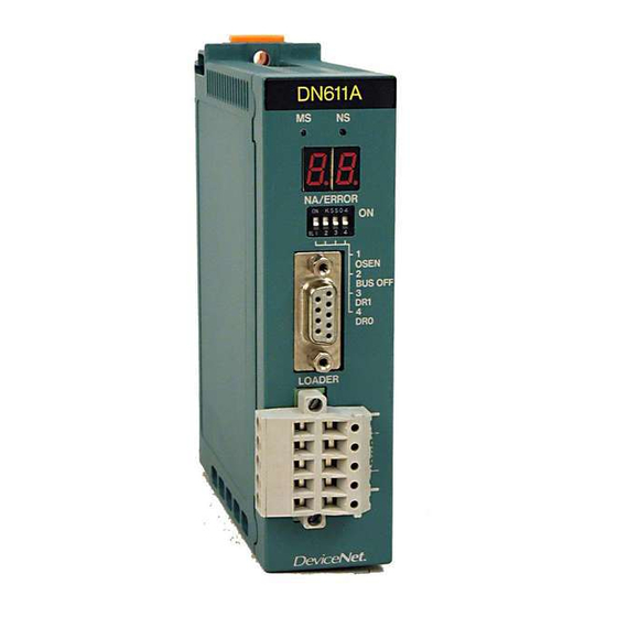
Chapter 2 Names and Functions of the Parts of the DN611 This chapter explains the names and functions of the parts of the DN611. 2.1 External Views, Dimensions, and Names of Parts Figure 2-1 External View and Dimensions (In millimeters) 6F8C0845... - Page 40 Chapter 2 Names and Functions of the Parts of the DN611 Figure 2-2 DN611 Dimensions (in mm) model 2000 DeviceNet Module Manual (DN611/DN611A)
- Page 41 2.1 External Views, Dimensions, and Names of Parts Module status (MS)/network status (NS) indicating LEDs Node address/error code indicating 7-segment LED Operation mode/communication rate setting DIP switches Test connector (D-SUB 9-pin) Device connector Network connector Figure 2-3 External View (Front) (in mm) 6F8C0845...
- Page 42 Chapter 2 Names and Functions of the Parts of the DN611 Network connector NA-H NA-L Node address setting rotary switches Figure 2-4 External View (Bottom) model 2000 DeviceNet Module Manual (DN611/DN611A)
-
Page 43: Functions Of The Parts
2.2 Functions of the Parts 2.2 Functions of the Parts (1) Module status and network status LEDs (MS/NS) These LEDs light in two colors, green and red, and blink to indicate the DN611's module status (MS) and network status (NS). Table 2-1 LED Indications Status Meaning (Main trouble) - Page 44 Chapter 2 Names and Functions of the Parts of the DN611 In the following cases, module or network status is displayed by combined indications of this LED and the module status and network status LEDs. • A trouble has occurred on the DN611 or on the network. •...
-
Page 45: Preparations For Operation (Hardware)
Chapter 3 Preparations for Operation (Hardware) 3.1 DN611 Setting Flowchart (Hardware) Warning 1. Configure an emergency-stop circuit, interlock circuit, and/or other similar circuits outside a PC and DN611. Trouble or malfunction of the S controller or DN611, if ever, can cause an accident, possibly leading to bodily injuries and/or mechanical damage. - Page 46 Chapter 3 Preparations for Operation (Hardware) The following flowchart shows the flow of DN611 setting. Start Set them with the DIP switches on the front panel Setting DN611 node address, and the rotary switches on the bottom. operation mode, communication rate For details, see 3.2 Setting the Switches.
-
Page 47: Setting The Switches
3.2 Setting the Switches 3.2 Setting the Switches The DN611 has DIP switches on the front panel and rotary switches on the bottom. 3.2.1 DIP switches for operation mode/communication rate setting ∼∼∼∼∼∼∼∼∼∼∼∼∼∼∼∼∼∼∼∼∼∼∼∼∼∼∼∼∼∼∼∼∼∼ For operation mode/ 動 作 モ ー ド /通 信 速 度 設 定 用 communication rate setting 工... - Page 48 Chapter 3 Preparations for Operation (Hardware) Caution 1. Keep the DIP switch OSEN in the OFF position. Setting it to ON can cause trouble or mal- function. 2. Set all the nodes connected to the network to the same communication rate. Different communication rates among the nodes will cause a slave device error or DN611 error, and disable to start communication.
-
Page 49: Rotary Switches For Node Address Setting
3.2 Setting the Switches 3.2.2 Rotary switches for node address setting The DN611 has rotary switches on the bottom for node address setting (0 to 63 in decimals) (Figure 3-3). NA-H is used for setting a figure in the digit of tens and NA-L, a figure in the digit of ones. - Page 50 Chapter 3 Preparations for Operation (Hardware) Usage Recommendations 1. If a node address anywhere from 64 to 99 is set, the DN611 will develop a node address set- ting error when the S controller is switched on. • The LED MS blinks red. •...
-
Page 51: Mounting In The Base Unit
3.3 Mounting in the Base Unit 3.3 Mounting in the Base Unit Mount your DN611 in the G2 I/O slot of the base unit for the S controller and lock it. For details, see the description of module installation in the Sequence Controller S2 User's Manual. -
Page 52: Connection To The Network
Chapter 3 Preparations for Operation (Hardware) 3.4 Connection to the Network This section describes how to connect the DeviceNet cables to the DN611. Caution 1. Do not connect the DeviceNet cables to, or disconnect them from, network connectors while the network is in operation. The wrong connection or a network shortcircuit, for example, may disable communication with other nodes. - Page 53 3.4 Connection to the Network The DN611 employs plug connectors (open type), and are provided with two types of network connectors as shown in Figure 3-4. The order of connecting the DeviceNet cables to the DN611 is as follows: (1) Connect the DeviceNet cables to the network connector and fix them. (2) Insert the network connector into the device connector on the front panel of the DN611.
-
Page 54: Connecting Devicenet Cables To Network
Chapter 3 Preparations for Operation (Hardware) 3.4.1 Connecting DeviceNet cables to network connector (1) Preparing DeviceNet Cables Prepare the DeviceNet cables to be connected to the network connector for the DN611 so their ends will be an open type (2 power cables, 2 signal cables, and 1 drain cable are discrete, that is, separated at the end). -
Page 55: Connecting Network Connector To The Dn611
3.4 Connection to the Network 3.4.2 Connecting network connector to the DN611 Insert the network connector into the device connector on front panel of the DN611. Note that the network connector cannot be inserted upside down due to its structure. Do not forcibly push it in. - Page 56 Chapter 3 Preparations for Operation (Hardware) Usage Recommendations 1. Loosen the cable clamp screws on the connector before inserting cables into the network connector. The cables cannot be fixed when the screws are kept tightened. 2. The colors corresponding to cable colors are printed on the device connector of the DN611. Match the cable colors with the printed colors to ensure the correct wiring.
-
Page 57: Network Power/Grounding
3.5 Network Power/Grounding 3.5 Network Power/Grounding In a DeviceNet network, the power for communication (24 VDC) is supplied through the DeviceNet power cables (V+/V-) via the network connector. This section describes network power supply to the DeviceNet cables and network power configuration. Grounding the network is also explained. -
Page 58: Network Power Configuration Method
Chapter 3 Preparations for Operation (Hardware) 3.5.2 Network power configuration method Usage Recommendations 1. In attaching nodes to drop cables, consider the current capacity of not only the trunk cables but also the drop cables. 2. In case of connecting nodes to drop cables in daisy-chain form, in particular, exercise care against inadequate current capacity. - Page 59 3.5 Network Power/Grounding • Thin cable trunk line: 3 A maximum Cable length 90m 100m Maximum current 3.00 3.00 3.00 2.06 1.57 1.26 1.06 0.91 0.80 0.71 0.64 細ケーブル最大電流 Maximum current for thick 3.00 2.50 2.00 1.50 1.00 0.50 0.00 Cable lengthcable ケーブル長...
- Page 60 Chapter 3 Preparations for Operation (Hardware) (2) How to determine the most appropriate arrangement of network power units Follow the procedures below to determine the most appropriate arrangement of network power units. (a) Total the network currents consumed by the individual nodes on the network. For the nodes operating on the network power, use the sum of both currents.
- Page 61 3.5 Network Power/Grounding (4) Single Power Unit Central Connection Shown below is an example of configuration where a network power unit is installed at the center of a trunk line (thick cable) 240 meters in overall length. The current consumption of each node is shown in the figure below. The central location of the network power unit permits supply of the maximum current in all directions of the network.
- Page 62 Chapter 3 Preparations for Operation (Hardware) Section 1 Section 2 セクション 1 セクション 2 120 m 120 m V +− 電源 Power Node 3 Node 2 Node 1 Node 4 Node 5 Node 6 タップ V − 1.1A 1.25A 0.5A 0.25A 0.25A 0.85A...
- Page 63 3.5 Network Power/Grounding Section 1 Section 2 セクション 1 セクション 2 100 m 140 m V +− 電源 Power Node 3 Node 2 Node 1 Node 4 Node 5 Node 6 タップ V − 1.1A 1.25A 0.5A 0.25A 0.25A 0.85A ネットワーク...
-
Page 64: Network Power Unit (24 Vdc)
Chapter 3 Preparations for Operation (Hardware) 3.5.3 Network power unit (24 VDC) Purchase network power units because they are not supplied with the DN611. Use network power units that meet the following specifications: Table 3-3 Network Power Unit Specifications Item Specifications 24 VDC ±1% Output voltage... -
Page 65: Network Grounding
3.5 Network Power/Grounding 3.5.4 Network grounding The DeviceNet requires 1-point grounding (Class D grounding exclusive to controllers) for the network. Grounding at two or more points can cause grounding loop. Conversely, an ungrounded network is likely to malfunction due to external noise. Use a power tap at the point of 1-point grounding. -
Page 66: Switching Power On And Off
Chapter 3 Preparations for Operation (Hardware) 3.5.5 Switching power on and off This section describes the order of switching on the slave devices, the network, and the S controller and of starting the DN611. Check all the devices that they have been wired and set as appropriate before proceeding to the following. -
Page 67: Network Components
3.6 Network Components (1) Starting the system (a) Network power ON (b) Slave device power ON (c) S controller power ON (d) Starting the DN611 for communication The DN611 doesn't start communication by simply switching the S controller on. Set the parameters of the local node and register the parameters of the slave devices on the scanning list before starting the DN611 for communication. - Page 68 Chapter 3 Preparations for Operation (Hardware) (1) Thick Cable (for trunk line) Manufacturer: Rockwell Automation Item name Catalog No. Remarks 1 m with connectors 1485C-P1N5-M5 1485C-P1N5-M5 Shielded mini-connectors (male, female) attached 2 m with connectors 1485C-P2N5-M5 Shielded mini-connector (male) at one end, 3 m with connectors 1485C-P3N5-M5 shielded mini-connector (female) at the other...
-
Page 69: Operating Procedures For The Dn611 (Software)
Chapter 4 Operating Procedures for the DN611 (Software) This chapter describes the items necessary for using the various functions of the DN611 in S controller ladder programs as follows: (1) DN611 registration In using the S controller with DN611s connected to it, it is necessary to register the DN611s as target stations. -
Page 70: Registering The Dn611
Chapter 4 Operating Procedures for the DN611 (Software) 4.1 Registering the DN611 The procedures for registering the DN611s in using them connected to the S controller are as follows: Register DN611s in the target station using the Engineering Tool. Supplementary Note •... - Page 71 4.1 Registering the DN611 Double-click here Figure 4-2 Configuration Editor (Before Module Registration) It is assumed here that the main unit has already been selected. Main unit: BU668: model 2000 main unit (single) 1 main +8I/O 6F8C0845...
- Page 72 Chapter 4 Operating Procedures for the DN611 (Software) (2) Module Connection Connect a DN611 into slot No. 6 of the main unit. Double-click a blank slot in [Module Inner Connection Configuration] under [Main Unit] to open the Module List menu. Choose "DN611"...
- Page 73 4.1 Registering the DN611 If this is in red, it has not been registered yet. If it is in black, it has been registered. Figure 4-4 Configuration Editor (After Module Registration) (3) Saving the registration Select [File] and [Save] on the CConfiguration Editor menu to save the DN611 registration.
-
Page 74: S Controller Interface Buffer Memory Configuration
Chapter 4 Operating Procedures for the DN611 (Software) 4.2 S Controller Interface Buffer Memory Configuration The operation of DN611 control and data input/output using the S controller is basically performed by reading and writing the S controller interface buffer memory with MREAD and MWRITE instructions. - Page 75 4.2 S Controller Interface Buffer Memory Configuration Shown below is the configuration of the S controller interface buffer memory as viewed from the S controller. The addresses of the communication memory are word addresses. 0000H Input/output data area 263 words 0106H 0107H RAS information area...
-
Page 76: Input/Output Data Areas
Chapter 4 Operating Procedures for the DN611 (Software) 4.2.1 Input/output data areas This area stores data between the DN611 and slave devices. Output data from the S controller is written in this area, while input data is read from this area. This area has output and input semaphore registers for synchronous communication between the DN611 and slave devices. - Page 77 4.2 S Controller Interface Buffer Memory Configuration (1) Input data semaphore Rregister (0106H: 1 word) This semaphore register is used to input data into the S controller from the DN611 (effective only in synchronous transmission mode). The register is used both in polling mode and bit strobe mode.
- Page 78 Chapter 4 Operating Procedures for the DN611 (Software) (4) Bit strobe output data area (0100H to 0103H: 4 words) This area stores data that the DN611 outputs to slave devices in bit strobe mode. The S controller ladder program writes output data in this area. The transmitting data in bit strobe mode is fixed at 8 bytes (64 bits).
- Page 79 4.2 S Controller Interface Buffer Memory Configuration (7) Use of output/input data semaphore (in synchronous transmission mode only) Figure 4-9 shows the relationship between the output data semaphore (polling/bit strobe) and input data semaphore. The shaded parts indicate each of the semaphore values is 1.
-
Page 80: Ras Information Area
Chapter 4 Operating Procedures for the DN611 (Software) 4.2.2 RAS information area This area shows the DN611's module status and status of communication with the network and slave devices. Don't write data in this area. Otherwise, there is a possibility of being unable to read the correct data. - Page 81 4.2 S Controller Interface Buffer Memory Configuration Details of the information that can be checked in the RAS information area are explained below. (1) Station status (02CEH: 1 word) This register indicates DN611 status with bit configuration flags. Each bit is significant at 1.
- Page 82 Chapter 4 Operating Procedures for the DN611 (Software) Table 4-3 Examples of DN611 Modes and Station Statuses DN611 mode Bit to turn 1 Station status Down mode DOWN 8000H After switching power on or after issuing a reset STBY 2000H request from the S controller Slave device is not registered in the DN611, or is STBY...
- Page 83 4.2 S Controller Interface Buffer Memory Configuration (2) Down Information (02CDH: 1 word) This register stores data of the cause of the DN611 getting into down mode. When this happens, the 7-segment LED on the front panel show the following down codes. Table 4-4 Down Information Down Code Cause of Down Mode...
- Page 84 Chapter 4 Operating Procedures for the DN611 (Software) (4) Completion of module initialization (02C6H: 1 word) This register indicates the completion of initializing after switching power on or by a reset request. "1": Initializing completed Other than "1": Initialization under way (5) Node error counter (02BFH to 02C5H: 7 words) The CAN controller used in the DN611 has a function of notifying error state changes of the local station (error active ↔...
- Page 85 4.2 S Controller Interface Buffer Memory Configuration Table 4-7 Slave Device Configuration Information Address 029FH Node address: 1 Node address: 0 02A0H Node address: 3 Node address: 2 02A1H Node address: 5 Node address: 4 02A2H Node address: 7 Node address: 6 02A3H Node address: 9 Node address: 8...
- Page 86 Chapter 4 Operating Procedures for the DN611 (Software) (7) Total number of devices (029EH: 1 word) Indicates the number of the slave devices to operate on the network specified by a parameter setting request from the S controller. (Setting information) (8) Number of online devices (029DH: 1 word) Indicates the number of the slave devices executing data input/output to and from the DN611.
- Page 87 4.2 S Controller Interface Buffer Memory Configuration (13)Input/output data setting information (010BH to 028AH: 384 words) Indicates to which part of the input/output data area is allocated the input/output data of each slave device (node address: NA). The input/output data setting information has 6 words per slave device.
- Page 88 Chapter 4 Operating Procedures for the DN611 (Software) Example: Input/output data setting information for node address = 1 • Input data offset indicates the offset address (in bytes) from the top (0000H) of input data area. • Output data offset indicates the offset address (in bytes) from the top (0080H) of output data area.
-
Page 89: Data Area
4.2 S Controller Interface Buffer Memory Configuration 4.2.3 Allocating slave device data to the input/output data area Reception/transmission data of slave devices will be allocated to the input/output data area in the ascending order of node addresses. In the slave device configuration shown in Table 4-11, for example, the node addresses are allocated to the input data area/output data area from the top downward without skipping as shown in Figure 4-13. -
Page 90: Semaphore Area
Chapter 4 Operating Procedures for the DN611 (Software) 4.2.4 Semaphore area This area is used to issue requests from the S controller for operating the DN611 in a specific way, or for reading the DN611's response to a request. The addresses shown in Figure 4-14 are the word addresses as viewed from the S controller. - Page 91 4.2 S Controller Interface Buffer Memory Configuration The S controller ladder program checks this register for "1" to be set after a request is issued to the DN611. When the "1" is set in the register, the ladder program reads DN611 response data from the acknowledgement area, then writes "0"...
- Page 92 Chapter 4 Operating Procedures for the DN611 (Software) Request area Acknowledgement S controller write area read Requested Acknowledgement flag Completion of register read acknowledgement Request flag area read register Request notice Request register Completion of request area read Acknow ledgement flag register Responded DN611...
-
Page 93: Requests To The Dn611
4.3 Requests to the DN611 4.3 Requests to the DN611 Use of a user function block combining MREAD and MWRITE instructions simplifies the program in controlling the DN611 and performing data input/output with the S controller. This section describes user function blocks for different types of requests (there are six of them) that the S controller issues to the DN611. -
Page 94: Dn611 Operation Modes
Chapter 4 Operating Procedures for the DN611 (Software) 4.3.1 DN611 operation modes The DN611 has the following operation modes: (1) Initialize mode • The DN611 is in the process of resetting after power is turned on or reset is requested. •... -
Page 95: Reset Request
4.3 Requests to the DN611 4.3.2 Reset request (1) Function This request is used to reset the DN611 from the S controller. Receiving a reset request, the DN611 initializes the module. This request also can delete the scan list (parameters of the slave devices connected to the network) stored in the internal non-volatile memory of the DN611. - Page 96 Chapter 4 Operating Procedures for the DN611 (Software) (3) Description of operation (a) When REQ is TRUE, the DN611 specified by CH, UNIT, and SLOT executes reset operation. If CLR_SL is "1," the scan list is also cleared. (b) After completion of initialize request processing, DONE is turned TRUE. (c) If initialize request processing is not completed in 10 seconds or more due to an error or the like, ERR and DONE are turned TRUE.
-
Page 97: Parameter Setting Request (Local Node)
4.3 Requests to the DN611 4.3.3 Parameter setting request (local node) (1) Function This request is used to set the local node parameters of the DN611. This request can be issued only when the DN611 is in standby mode. After setting the local node parameters and slave device parameters, set the DN611 in run mode (transmission enabled) by following 4.3.5 Operation mode control request. - Page 98 Chapter 4 Operating Procedures for the DN611 (Software) (4) Local node parameter (PARA_LOCAL) PARA_LOCAL structure PORT WORD type Port No. LOCAL_ADR WORD type Local node address POL_TRMODE WORD type Polling transmission mode SCAN_INTERVAL WORD type Scan interval waiting time BGPOL_RATIO WORD type Background poll ratio RETR_CNT...
- Page 99 4.3 Requests to the DN611 (b) Polling transmission mode = 1 • The master device checks the polling slave devices for response and makes a polling request to the individual slave devices in sequence. If there is no polling response from a slave device, the master device waits for 20 ms before making a polling request to the next slave device.
-
Page 100: Parameter Setting Request (Slave Devices)
Chapter 4 Operating Procedures for the DN611 (Software) 4.3.4 Parameter setting request (Slave devices) (1) Function This request is used to set slave devices parameters in the DN611 scan list. This request can be issued only when the DN611 is in standby mode. Up to 10 salve devices can be set per parameter setting request. - Page 101 4.3 Requests to the DN611 (4) Slave device parameters PARA_SLAVE structure DEVICE_ARRAY [0...9] Structural data type Slave device parameter set value DEVICE structure PORT WORD type Port No. SLAVE_ADR WORD type Slave node address VENDOR_ID WORD type Vendor ID P_TYPE D type Product type P_CODE...
- Page 102 Chapter 4 Operating Procedures for the DN611 (Software) Note that the DN611 is subject to the following restrictions on transmission in size 0 byte to polling type slave devices. Restrictions • When a slave device fails in communication with the DN611 due to some reason (slave device power off or connector removed, for example), the DN611 cannot recognize whether the slave device is abnormal.
-
Page 103: Operation Mode Control Request
4.3 Requests to the DN611 4.3.5 Operation mode control request (1) Function This request is used to specify an operation mode for the DN module. It is valid if the DN611 is in neither down mode nor initialize mode. Run mode (transmission enabled) is available only when the DN611 is in standby mode and has its local node parameters set. - Page 104 Chapter 4 Operating Procedures for the DN611 (Software) (4) Operation mode specifying information: 1 is significant in any of these bits. STBY BITS START POLL SYNC Figure 4-18 Bit Configuration of Operation Mode Specifying Information Table 4-15 Description of Operation Mode Specifying Information Bits Name Description STBY...
-
Page 105: Ras Information Read Request
4.3 Requests to the DN611 4.3.6 RAS Information read request (1) Function This request reads the DN611's RAS information from the S controller. There are three kinds of RAS information read by this request: RAS history counter, event history, and execution node information (slave device execution information possessed by the DN611). - Page 106 Chapter 4 Operating Procedures for the DN611 (Software) (4) Others (a) RETYPE (Type of request information) is as follows: 1: RAS history 2: Event history 3: Execution node information 4: RAS information clear (b) POSITION (read start position) is valid for the read request "event history" only. To read other types of request, enter 0.
-
Page 107: Time Setting Request
4.3 Requests to the DN611 4.3.7 Time setting request (1) Function This request sets the time in the DN611. The time thus set is used for event history data. When the DN611 is in down mode or initialize mode, this function cannot be used. -
Page 108: User Function Block For Slave Data Input/Output
Chapter 4 Operating Procedures for the DN611 (Software) 4.4 User Function Block for Slave Data Input/Output MREAD and MWRITE instructions are used for the S controller to access the input/ output data areas of the DN611, which store data to output to slave devices and input data received from them. - Page 109 4.4 User Function Block for Slave Data Input/Output Input Argument Output Argument BOOL type Execution enabled DONE BOOL type Completed WORD type Channel No. BOOL type Error UNIT WORD type Unit No. STATUS WORD type Station status SLOT WORD type Slot No.
- Page 110 Chapter 4 Operating Procedures for the DN611 (Software) (a) Use this function block when the DN611 is in run mode. (b) When REQ is TRUE, data is input and output to and from the DN611 specified by CH, UNIT, and SLOT. Data from two or more slave devices can be sent or received because an input/output data area can be specified.
- Page 111 4.4 User Function Block for Slave Data Input/Output Table 4-17 Operation of Input/Output Data Area Batch Access Function Block Data transfer between S Polling/Bit Strobe Function Block Operation controller and DN611 Asynchronous Both • Output data write in polling output data area and bit strobe output data area •...
-
Page 112: Confirming The Allocations
Chapter 4 Operating Procedures for the DN611 (Software) 4.4.2 Confirming the allocations (1) Function Where in the input/output data areas of the DN611 the input/output data of a specified slave device are allocated is calculated. Based on this allocation information, the input/output data are read or written using an MREAD or MWRITE instruction. -
Page 113: Slave Data Input (Asynchronous Mode Only)
4.4 User Function Block for Slave Data Input/Output 4.4.3 Slave data input (Asynchronous mode only) (1) Function During operation in asynchronous mode, input data to a specified slave device is read from the input data area of the DN611. (2) Diagrammatic Representation (Function block) DN_ASREAD DONE UNIT... - Page 114 Chapter 4 Operating Procedures for the DN611 (Software) (3) Description of operation DN611 S controller Slave device ASREAD_DT Input data Polling/bit strobe Polling register area input data area Bit strobe Figure 4-20 Slave Data Input Function Block Data Input (a) Use this function block when the DN611 is in run mode. (b) The allocation confirmation (DN_INSTRUCT) function block mentioned above is used inside this function block.
-
Page 115: Slave Data Output (Asynchronous Mode Only)
4.4 User Function Block for Slave Data Input/Output 4.4.4 Slave data output (Asynchronous mode only) (1) Function During operation in asynchronous mode, output data to a specified slave device is written in the output data area (bit strobe or polling) of the DN611. (2) Diagrammatic Representation (Function block) DN_ASWRITE DONE... - Page 116 Chapter 4 Operating Procedures for the DN611 (Software) (3) Description of operation DN611 S controller Slave device ASW RITE_DT Polling Polling output data area Output data register area ASW RITE_DT Bit strobe output Bit strobe data area Figure 4-21 Slave Data Output Function Block Data Output (a) Use this function block when the DN611 is in run mode.
-
Page 117: Completion Status
4.5 Completion Status 4.5 Completion Status The completion statuses that DN611 returns in response to the requests issued by the S controller are shown below. Except for normal completion, an error code and the local node address are alternately indicated by the 7-segment LED on the front panel of the DN611. The error code indication stops when the following request is completed normally. -
Page 119: Example Of Use Of The Dn611
Chapter 5 Example of Use of the DN611 This chapter describes an example of operating the DN611 from the S controller and sample ladder programs. Caution 1. Fully understand the description of this chapter before preparing your program m. The sam- ple program here is a basic example, and requires an adequate study before applying it to an actual system. -
Page 120: System Configuration Of The Example
Chapter 5 Example of Use of the DN611 5.1 System Configuration of the Example The example system is described up to slave device input/output. DeviceNet module (DN611) S2CPU Channel: 0; Unit: 0; Slot: 6 Slot 0 Node address (NA): 00 Engineering Tool NA:20... -
Page 121: Operating Sequence
5.2 Operating Sequence 5.2 Operating Sequence Figure 5-2 shows the flow of DeviceNet module operation from initializing to module parameter setting, operation mode control, output data write, and input data read. Reset request Reset (or switching power on) Parameter setting (local node) Parameter setting(slave devices) * * Unnecessary if scan list has already been prepared. -
Page 122: Slave Data Input/Output
Chapter 5 Example of Use of the DN611 5.3 Slave Data Input/Output (1) Structure declaration TYPE (*======================================================== Structure(User0) ========================================================*) TypeP_LOCAL:STRUCT(*Local node parameter set value*) PORT :WORD; (*Port number*) LOCAL_ADR :WORD; (*Local node address*)) POL_TRMODE :WORD; (*Polling transmission mode*) SCAN_INTERVAL :WORD; (*Scan interval*) BGPOL_RATIO :WORD;... - Page 123 (*======================================================== User variable (S2-type2).var Applicable controller: S2-type2 Address range: %MW4.0 - %MW4.5119 Explanation: User free use area ------------------------------------------------------------------------------------------- 1999-05-27: by TOSHIBA : Greated ========================================================*) (*Devicenet structure*) PARA_LOCAL :typeP_LOCAL; (*Local node parameter set value*) PARA_SLAVE :typeP_SLAVE; (*Slave device parameter set value*) ASREAD_DT :typeASREADDAT;...
- Page 124 Chapter 5 Example of Use of the DN611 TMR1 :TON_100ms; (*Power ON delay*) TIME1 :DINT; (*Power ON delay time*) RESET :BOOL; (*Initialize request*) END_RESET :BOOL; (*Initialize end*) RESET_ERR :BOOL; (*Initialize error*) DN_RESET_1 :DN_RESET; (*Initialize request*) STS_RESET :WORD; (*Initialize status*) LOCALSET :BOOL;...
- Page 125 5.3 Slave Data Input/Output (4) Sample Program /*Channel number, unit number, slot number specify*/ MOVE_WORD UNIT MOVE_WORD SLOT MOVE_WORD /*Reset request 3 seconds after power ON*/ TMR1 START RESET TON_100ms ↑ TIME1 DN_RESET_1 END_RESET RESET DN_RESET DONE RESET_ERR STS_RESET UNIT UNIT STATUS SLOT...
- Page 126 Chapter 5 Example of Use of the DN611 /*Parameter setting request (local node)*/ END_RESET RESET_ERR LOCALSET ↑ RESET PARA_LOC 16#0 AL.PORT MOVE_WORD PARA_LOC PARA_LOC AL.BGPOL AL.LOCAL 16#1 16#0 _ADR _RATIO MOVE_WORD MOVE_WORD PARA_LOC PARA_LOC AL.RETR_ AL.POL_T 16#1 16#0 RMODE MOVE_WORD MOVE_WORD PARA_LOC PARA_LOC...
- Page 127 5.3 Slave Data Input/Output N_SLAVE MOVE_UNIT PARA_SLA PARA_SLA PARA_SLA VE.DEV[0]. VE.DEV[1]. VE.DEV[2]. 16#0 16#0 16#0 PORT PORT PORT MOVE_WORD MOVE_WORD MOVE_WORD PARA_SLA PARA_SLA PARA_SLA VE.DEV[1]. VE.DEV[2]. VE.DEV[0]. 16#2 16#3 16#1 SLAVE_ SLAVE_ SLAVE_ MOVE_WORD MOVE_WORD MOVE_WORD PARA_SLA PARA_SLA PARA_SLA VE.DEV[1]. VE.DEV[2].
- Page 128 Chapter 5 Example of Use of the DN611 PARA_SLA PARA_SLA VE.DEV[4]. VE.DEV[3]. 16#0 16#0 PORT PORT MOVE_WORD MOVE_WORD PARA_SLA PARA_SLA VE.DEV[4]. 16#1B 16#14 SLAVE_ DEV[3].SLA MOVE_WORD MOVE_WORD VE_ADR PARA_SLA PARA_SLA VE.DEV[4]. VE.DEV[3]. 16#1 16#1 VENDOR VENDOR MOVE_WORD MOVE_WORD PARA_SLA PARA_SLA VE.DEV[4].
- Page 129 5.3 Slave Data Input/Output DN_SLAVESET_1 END_SLAVE SLAVESET DN_SLAVESET DONE SLAVESET _ERR STS_SLAVE UNIT UNIT STATUS SLOT SLOT N_SLAVE PARA_SLAVE PARA_SLAVE /*Operation mode control request*/ END_SLAVE SLAVESET _ERR MODESET ↑ SLAVESET DN_MODESET_1 END_MODE MODESET DN_MODESET DONE MODESETE STS_MODE UNIT UNIT STATUS SLOT SLOT 16#1610...
- Page 130 Chapter 5 Example of Use of the DN611 */Slave data output (Asynchronous mode)*/ DN_ASWRITE_1 END_ASWR ASWRITE DN_ASWRITE DONE ASWRITE_ STS_ASWR UNIT UNIT STATUS SLOT SLOT NODE ASWRITE_ ASWRITE_DT END_ASWR ASREAD ASWRITE */Slave data input (Asynchronous mode)*/ DN_ASREAD_1 END_ASRE ASREAD DN_ASREAD DONE ASREAD_ STS_ASRE...
- Page 131 5.3 Slave Data Input/Output (5) Explanations (a) Reset request • Set a DeviceNet module channel number, unit number, and slot number for the variables CH, UNIT, and SLOT. (The same setting process is repeated many times, so if a module position is changed, the settings can be changed collectively.
- Page 132 Chapter 5 Example of Use of the DN611 Table 5-2 Slave Device Parameter Sample Parameter Setting Name Value Number of requested devices DEVICE[0]. First slave device setting information PORT Port number SLAVEADR Slave node address VENDOR_ID Vendor ID P_TYPE Product type P_CODE Product code SCANTYPE...
- Page 133 5.3 Slave Data Input/Output • As in the case of ASWRITTE, values for CH, UNIT, and SLOT are entered using the variables (CH, UNIT, SLOT) set by an initialize request. A read/ write node address is entered for NODE. 0 is entered for BS in polling mode, or 1 BS in bit strobe mode.
-
Page 134: Other Functions
Chapter 5 Example of Use of the DN611 5.4 Other Functions (1) Definitions of Variables (*========================================================== DeviceNet DN611 Sample Program (Other Functions) ==========================================================*) VAR_EXTERNAL RAS_DT :typeRASDT; (*RAS information read data*) TIME_DT :typeTIMEDT; (*Time set*) :ARRAY[0..511] OF INT; (*SW register INT access*) END_VAR :WORD;... - Page 135 5.4 Other Functions (2) Sample Program /*Channel number, unit number, slot number specify*/ MOVE_WORD UNIT MOVE_WORD SLOT MOVE_WORD /*Slave device allocation confirmation*/ DN_INSTRUCT_1 END_INST INSTRUCT RUCT DN_INSTRUCT DONE INSTRUCT _ERR STS_INST RUCT UNIT UNIT STATUS READ_INS TW[0] SLOT SLOT BS_ADD READ_INS TI[0] 16#1...
- Page 136 Chapter 5 Example of Use of the DN611 /*RS information read request*/ DN_RASREAD_1 END_ RASR RASREAD DN_RASREAD DONE RASREAD _ERR STS_ RASR UNIT UNIT STATUS RAS_DT SLOT SLOT RAS_DT REQTYPE POSITION RAS_DT. READ_ RASDAT[0] RASDATA[0] TMOV /*Time setting request*/ TIME_DT. TIME_DT.
- Page 137 5.4 Other Functions (3) Explanations (a) Allocation confirmation • This function is valid in run mode only. • The start relay INSTRUCT is turned TRUE to start operation. • Values for CH, UNIT, and SLOT are entered using the variables (CH, UNIT, SLOT) set by an initialize request.
-
Page 139: Ras Information (Except For Ras Area In Communication Memory)
Chapter 6 RAS Information (Except for RAS Area in Communication Memory) This chapter describes the following RAS functions of the DN611. (1) Indicators on the front panel • Module status/network status LED (MS/NS) • 7-segment LED (NA/ERROR) (2) Information by reading RAS Information •... -
Page 140: Module Status (Ms)/Network Status (Ns) Leds
Chapter 6 RAS Information (Except for RAS Area in Communication Memory) 6.1 Module Status (MS)/Network Status (NS) LEDs The 2-color light-emitting diode (LED) on the front panel of the DN611 (module status/ network status LED) indicates module status (MS) and network status (NS) in two colors (green and red) and by ON, blink, and OFF. -
Page 141: Indications Of The 7-Segment Led
6.2 Indications of the 7-Segment LED 6.2 Indications of the 7-Segment LED The 7-segment LED (NA/ERROR) on the front panel of the DN611 indicates node addresses and error codes. When the DN611 is transmitting normally with slave devices, the local station node address (value set by the rotary switches on the front panel of the module) is displayed. - Page 142 Chapter 6 RAS Information (Except for RAS Area in Communication Memory) Table 6-3 Combined Indications of the 7-segment LED and 2-Color LED M: DN611 node address S: Slave device node address 7-segment Description 77 ↔ S Green Transmission size different from the actual size has been set blinking as slave device parameter.
-
Page 143: Ras Information Read Data
6.3 RAS Information Read Data 6.3 RAS Information Read Data This section describes the RAS information of the DN611 (RAS counter, event history, executing node information) read by the ladder program. See 4.3.6 RAS Information read request for details on this request. 6.3.1 RAS Counter When request information type 1 is set for RAS information read request, the RAS... - Page 144 Chapter 6 RAS Information (Except for RAS Area in Communication Memory) Table 6-4 RAS Counter List (2/3) Symbol name Address Description RAS_CNT[23] 02DEH H Number of output data write requests (bit strobe) RAS_CNT[24] 02DFH L Number of output data write responses (bit strobe) RAS_CNT[25] 02DFH H Number of output data write requests (polling)
- Page 145 6.3 RAS Information Read Data Table 6-4 RAS Counter List (3/3) Symbol name Address Description RAS_CNT[63] 02F2H H Received maximum data length different (No fragment) RAS_CNT[64] 02F3H L Connection table fragment buffer acquisition failure RAS_CNT[65] 02F3H H Fragment data type error RAS_CNT[66] 02F4H L Fragment data intermediate counter error...
-
Page 146: Event History
Chapter 6 RAS Information (Except for RAS Area in Communication Memory) 6.3.2 Event History When request information type 2 is set for RAS information read request, event history data can be read into the acknowledgement area. Acknowledgement Area 02D0H Request code (0015H) 02D1H Completion status 02D2H... - Page 147 6.3 RAS Information Read Data Table 6-5 Event Trace Items (1/3) Event Detail Detail Detail Detail Description Code Information 1 (H) Information 2 (H) Information 3 (H) Information 4 (H) 0001H Down code 1: Memory check Content of read port Module down 2: TRAP Content of WDT_FLG...
- Page 148 Chapter 6 RAS Information (Except for RAS Area in Communication Memory) Table 6-5 Event Trace Items (2/3) Event Detail Detail Detail Detail Description Code Information 1 (H) Information 2 (H) Information 3 (H) Information 4 (H) 0200H Request ID Request code Completion status 0241H Request device ID Scan type...
-
Page 149: Execution Node Information
6.3 RAS Information Read Data 6.3.3 Execution node information When request information type 3 is set for RAS information read request, slave device execution information (module status and 7-segment LED status indications) can be read into the acknowledgement area. Acknowledgement Area 02D0H Request code (0015H) 02D1H... - Page 150 Chapter 6 RAS Information (Except for RAS Area in Communication Memory) Table 6-7 Module Status Codes Module Status Code Description 0 (00H) Normal status 1 (01H) Transmission not enabled 2 (02H) No data flow in the transmission line 3 (03H) Communication error 4 (04H) Scan list disagrees with the actual slave composition.
- Page 151 6.3 RAS Information Read Data Table 6-9 7-Segment LED Status Codes Module Status Code Description 70 (46H) DN611 detects an error in duplicate node address check. 72 (48H) DN611 cannot communicate with slave devices. 73 (49H) Vendor ID, product type, and product code of a slave device differ from those on the DN611 scan list.
-
Page 153: Troubleshooting
(2) Set in down mode during communication with slave devices Countermeasure Replace the module. Record the down information before replacing the module (as noted on the module front). Send the module which has run down and the down information to TOSHIBA. 6F8C0845... -
Page 154: Reset Request (Scan List Clear)
Replace the module. Read the down information and send it together with the module to TOSHIBA. Figure 7-2 Reset Request Check Items (2) The Module doesn't return to standby mode at the reset request of Scan List Clear. -
Page 155: No Run Mode
7.3 No Run Mode 7.3 No Run Mode The explanations in this section are based on the assumption that the module has started normally. To change the mode from standby to run after starting the module, it is necessary to set the local node parameters by a parameter setting request before issuing an operation mode control request. - Page 156 Chapter 7 Troubleshooting (2) Slave device parameter setting request START Is the parameter setting Execute the slave device parameter request executed? setting request. (See 4.3.4.) See how to use semaphore area in 4.2.4. Is the parameter setting request completed? It takes about 4 seconds for the slave device parameter Remove the cause of trouble setting request to set one slave.
-
Page 157: Data Communication With Slave Devices
7.4 Data Communication with Slave Devices 7.4 Data Communication with Slave Devices (1) Data communication with slave devices doesn't start If the 7-segment LED indicates an error, remove the cause of the trouble, referring to 6.2 Indications of the 7-Segment LED. Table 7-1 Slave Device Communication Check Items (1) Description of Check DN711... - Page 158 Chapter 7 Troubleshooting (2) Communication with slave devices interrupted If the 7-segment LED indicates an error code, remove the cause of the trouble, referring to 6.2 Indications of the 7-Segment LED. Table 7-2 Slave Device Communication Check Items (2) Description of Check DN611 Check S controller power.
-
Page 159: Installation And Wiring
Chapter 8 Installation and Wiring 8.1 Installation Environment and Mounting the Base Unit Use your DN611 in the installation environment specified in the Installation Environment of the Sequence Controller User's Manual - Basic Hardware. Also, follow the instructions specified in Installation Environment in installing the cabinet containing your DN611. Read the instructions for the base unit mounting specified in the Sequence Controller User's Manual - Basic Hardware before mounting the base unit. -
Page 160: Mounting/Removing The Module
Chapter 8 Installation and Wiring 8.2 Mounting/Removing the Module Follow the instructions specified in the section Mounting the Module of the Sequence Controller User's Manual - Basic Hardware in mounting or removing the module. Caution 1. Since the DN611 is designed for the model 2000 of the Integrated Controller V Series, be sure to mount your DN611 in the base unit, instead of using it alone. - Page 161 8.3 Power Cable Wiring/Grounding Caution 1. Be sure to switch power off before installing cables. Installing cables without switching power off can cause electric shock. 2. For cabling the S controller power module, either use a crimp terminal with sheath, or cover the cable end with tape to keep the conductors unexposed.
-
Page 162: Network Installation
Chapter 8 Installation and Wiring 8.4 Network Installation Refer to 3.6 Network Components for the components that constitute the network. This section describes the procedures both for trunk line and drop line cabling. Caution Basic Precautions for Network Installation 1. Ask a qualified service agent for DeviceNet cabling because it requires safety and anti-noise measures. - Page 163 8.4 Network Installation (2) Installation without piping • For cable protection, either pass the cables through a floor duct or use a wire pro- tector cable cover. In this case, do not lay them together with wires or cables car- rying high current or high voltage.
-
Page 164: Cabling Inside The Cubicle
Chapter 8 Installation and Wiring Source: Guideline for the Environment of Installing Microcomputer-applied Instrumentation and Control Devices (by the [Japan Electric Measuring Instruments Manufacturers' Association]) In case of using a cable duct, place a steel-made separator in a cable duct and separate the power cables from the trunk cables as shown below. -
Page 165: A Maintenance And Inspection
Appendix A Maintenance and Inspection <Periodic Inspection> Check the following items periodically (about every six months). Also check them if the ambient conditions have changed. Table A-1 Periodic Inspection Items Check Item Description Judging Standardt Remedy Power-related Measure voltages at Within the specified Keep the input voltage items... - Page 166 1. If your DN611 does not operate normally, identify the cause of the trouble, referring to Chap- ter 7 Troubleshooting. If it should fail, contact your nearest TOSHIBA office, or dealer, or service shop, and send your DN611 back for repairs.
-
Page 167: B Read Instruction/Write Instruction Execution Time
Appendix B READ Instruction/ WRITE Instruction Execution Time Table B-1 MREAD Instruction/MWRITE Instruction Execution Time (µs) MREAD Instruction 14.72 (4+N) x I/O access time MWRITE Instruction 14.48 (4+N) x I/O access time N: Number of words to transfer I/O access time = 8.72µs I/O access time = 8.72µs Table B-2 Maximum Execution Time for DN611 Access (ms) (128 words for input/output) -
Page 169: Block
Appendix C Definition of Each Request Function Block C.1 Reset Request Function Block (1) Definitions of Variables (*=================================================== DeviceNet FB Reset Request ===================================================*) VAR_INPUT REQ: BOOL; (*Execution request*) WORD; (*Channel specify*) UNIT: WORD; (*Unit specify*) SLOT: WORD; (*Slot specify*) CLR_SL: WORD;... - Page 170 Appendix C Definition of Each Request Function Block NUM_WRT2: UINT; (*Number of words to transfer) DUMMY_W3: BOOL; (*Dummy*) ADR_WRT3: WORD; (*Extension memory address*) DAT_WRT3: WORD; (*Transfer source variable*) NUM_WRT3: UINT; (*Number of words to transfer) TMR1: TON_100ms (*Acknowledgement wait timer*) TIME1: DINT;...
- Page 171 C.1 Reset Request Function Block (2) Program /*Slot settings calculation*/ TMP_CH UNIT TMP_UNIT SHL_WORD SHL_WORD TMP_CH TMP_CHUNIT TMP_CHUNIT SLOTNO OR_WORD OR_WORD TMP_UNIT SLOT /*Model selection*/ SW[0] SW[0] EQ_INT EQ_INT ( ) ( ) /*Step initializing*/ DEF1 STEP[0] MOVE_WORD STATUS STEP[1] 16#0 〉 SET STEP[2] STEP[3] STEP[4]...
- Page 172 Appendix C Definition of Each Request Function Block /*Request area write: Initialize request*/ DUMMY_W1 MOVE_WORD ADR_WRT1 1832 〉 SET MOVE_WORD ADR_WRT1 〉 SET DAT_WRT1[0] MOVE_WORD CLR_SL DAT_WRT1[1] MOVE_WORD NUM_WRT1 MOVE_UINT STEP[0] STEP[1] MWRITE STEP[0] SLOTNO ADR_WRT1 TADDR DAT_WRT1 NUM_WRT1 model 2000 DeviceNet Module Manual (DN611/DN611A)
- Page 173 C.1 Reset Request Function Block /*Write 1 in request flag register*/ DUMMY_W2 MOVE_WORD 2035 ADR_WRT2 〉 SET MOVE_WORD ADR_WRT2 1021 DAT_WRT2 MOVE_WORD NUM_WRT2 MOVE_UINT STEP[1] STEP[2] MWRITE STEP[1] SLOTNO ADR_WRT2 TADDR DAT_WRT2 NUM_WRT2 6F8C0845...
- Page 174 Appendix C Definition of Each Request Function Block /*Write 1 in request register*/ DUMMY_W3 MOVE_WORD MOVE_WORD ADR_WRT3 DAT_WRT3 2047 〉 SET 〉 SET MOVE_WORD MOVE_WORD ADR_WRT3 DAT_WRT3 1023 〉 SET 〉 SET NUM_WRT3 MOVE_UINT STEP[2] STEP[3] MWRITE STEP[2] SLOTNO ADR_WRT3 TADDR DAT_WRT3 NUM_WRT3...
- Page 175 C.1 Reset Request Function Block /*Acknowledgement flag register read*/ DUMMY_R1 MOVE_WORD ADR_RED1 2034 〉 SET MOVE_WORD ADR_RED1 1020 〉 SET NUM_RED1 MOVE_UINT STEP[4] COMP_RED1 MREAD SLOTNO ADR_RED1 TADDR DAT_RED1 NUM_RED1 /*To Step 5 if acknowledgement flag register = 1*/ DAT_RED1 COMP_RED1 STEP[5] EQ_WORD...
- Page 176 Appendix C Definition of Each Request Function Block /*Acknowledgement area (error status) read*/ DUMMY_R2 MOVE_WORD ADR_RED2 1632 〉 SET MOVE_WORD ADR_RED2 〉 SET NUM_RED2 MOVE_UINT STEP[5] COMR_RED2 MREAD SLOTNO ADR_RED2 TADDR DAT_RED2 NUM_RED2 DAT_RED2[0] COMP_RED2 STEP[6] EQ_WORD STEP[5] DAT_RED2[1] STATUS MOVE_WORD model 2000 DeviceNet Module Manual (DN611/DN611A)
- Page 177 C.1 Reset Request Function Block /*Write 0 in acknowledgement flag register*/ DUMMY_W4 MOVE_WORD ADR_WRT4 2034 〉 SET MOVE_WORD ADR_WRT4 1020 〉 SET DAT_WRT4 MOVE_WORD NUM_WRT4 MOVE_UINT STEP[6] STEP[9] MWRITE STEP[6] SLOTNO ADR_WRT4 TADDR DAT_WRT4 NUM_WRT4 6F8C0845...
- Page 178 Appendix C Definition of Each Request Function Block /*Station status read*/ DUMMY_R3 MOVE_WORD ADR_RED3 1493 〉 SET MOVE_WORD ADR_RED3 〉 SET NUM_RED3 MOVE_UINT STEP[8] COMR_RED3 MREAD SLOTNO ADR_RED3 TADDR DAT_RED3 NUM_RED3 model 2000 DeviceNet Module Manual (DN611/DN611A)
- Page 179 C.1 Reset Request Function Block /*To Step 9 after station status confirmation*/ ST_STATUS DAT_RED3 MOVE_WORD ST_STATUS COMP_RED3 CMP_RES1 EQ_WORD 8192 DAT_WRT1[1] CMP_RES2 COMP_RED3 EQ_WORD CMP_RES1 CMP_RES2 STEP[9] STEP[8] ST_STATUS COMP_RED3 CMP_RES3 EQ_WORD 8256 COMP_RED3 CMP_RES4 DAT_WRT1[1] EQ_WORD CMP_RES3 CMP_RES4 STEP[9] MOVE_WORD STATUS STEP[8]...
- Page 180 Appendix C Definition of Each Request Function Block C.2 Parameter Setting Request (Local Node) Function Block (1) Definitions of Variables (*=================================================== DeviceNet FB Parameter Setting Request (Local Node) ===================================================*) VAR_INPUT REQ: BOOL; (*Execution request input*) WORD; (*Channel specify*) UNIT: WORD; (*Unit specify*) SLOT: WORD;...
- Page 181 C.2 Parameter Setting Request (Local Node) Function Block NUM_WRT3: UINT; (*Number of words to transfer) DUMMY_R1: BOOL; (*Dummy*) ADR_RED1: WORD; (*Extension memory address*) DAT_RED1: WORD; (*Transfer destination variable*) NUM_RED1: UINT; (*Number of words to transfer) COMP_RED1: BOOL; (*Completion*) DUMMY_R2: BOOL; (*Dummy*) ADR_RED2: WORD;...
- Page 182 Appendix C Definition of Each Request Function Block (2) Program /*Slot settings calculation*/ TMP_CH UNIT TMP_UNIT SHL_WORD SHL_WORD TMP_CH TMP_CHUNIT TMP_CHUNIT SLOTNO OR_WORD OR_WORD TMP_UNIT SLOT /*Type identifying*/ SW[0] SW[0] EQ_INT EQ_INT ( ) ( ) /*Step initializing*/ DEF1 STEP[0] MOVE_WORD STATUS STEP[1] 16#0 〉...
- Page 183 C.2 Parameter Setting Request (Local Node) Function Block /*Request area write: Local node parameter setting request*/ DUMMY_W1 MOVE_WORD ADR_WRT1 1832 〉 SET MOVE_WORD ADR_WRT1 〉 SET PARA_LOC INPUTDAT[0] INPUTDAT[5] 16#12 AL.SCAN_ MOVE_WORD INTERVAL MOVE_WORD PARA_LOC 16#0 INPUTDAT[1] AL.BGPOL_ INPUTDAT[6] MOVE_WORD RATIO MOVE_WORD PARA_LOC...
- Page 184 Appendix C Definition of Each Request Function Block /*Write 1 in request flag register*/ DUMMY_W2 MOVE_WORD 2035 ADR_WRT2 〉 SET MOVE_WORD 1021 ADR_WRT2 DAT_WRT2 MOVE_UINT NUM_WRT2 MOVE_UINT STEP[1] STEP[2] MWRITE STEP[1] SLOTNO ADR_WRT2 TADDR DAT_WRT2 NUM_WRT2 model 2000 DeviceNet Module Manual (DN611/DN611A)
- Page 185 C.2 Parameter Setting Request (Local Node) Function Block /*Write 1 in request register*/ DUMMY_W3 MOVE_WORD MOVE_WORD ADR_WRT3 DAT_WRT3 2047 〉 SET 〉 SET MOVE_WORD MOVE_WORD ADR_WRT3 DAT_WRT3 1023 〉 SET 〉 SET NUM_WRT3 MOVE_UINT STEP[2] STEP[3] MWRITE STEP2 SLOTNO ADR_WRT3 TADDR DAT_WRT3 NUM_WRT3...
- Page 186 Appendix C Definition of Each Request Function Block /*Acknowledgement flag register read*/ DUMMY_R1 MOVE_WORD ADR_RED1 2034 〉 SET MOVE_WORD ADR_RED1 1020 〉 SET NUM_RED1 MOVE_UINT STEP[3] COMP_RED1 MREAD SLOTNO ADR_RED1 TADDR DAT_RED1 NUM_RED1 DAT_RED1 COMP_RED1 STEP[4] EQ_WORD STEP[3] model 2000 DeviceNet Module Manual (DN611/DN611A)
- Page 187 C.2 Parameter Setting Request (Local Node) Function Block /*Acknowledgement area (completion status) read*/ DUMMY_R2 MOVE_WORD ADR_RED2 1632 〉 SET MOVE_WORD ADR_RED2 〉 SET NUM_RED2 MOVE_UINT STEP[4] COMR_RED2 MREAD SLOTNO ADR_RED2 TADDR DAT_RED2 NUM_RED2 CMP_RES1 DAT_RED2[0] COMP_RED2 EQ_WORD DAT_RED2[1] COMP_RED2 CMP_RES2 EQ_WORD DAT_RED2[1] STATUS...
- Page 188 Appendix C Definition of Each Request Function Block /*Write 0 in acknowledgement flag register*/ DUMMY_W4 MOVE_WORD 2034 ADR_WRT4 〉 SET MOVE_WORD ADR_WRT4 1020 DAT_WRT4 MOVE_WORD NUM_WRT4 MOVE_UINT STEP[5] STEP[6] MWRITE STEP[5] SLOTNO ADR_WRT4 TADDR DAT_WRT4 NUM_WRT4 /*End*/ STEP[6] DONE TMR1 STEP[6] TON_100ms TIME1...
- Page 189 C.3 Parameter Setting Request (Slave) Function Block C.3 Parameter Setting Request (Slave) Function Block (1) Definitions of Variables (*=================================================== DeviceNet FB Parameter Setting (Slave) ===================================================*) REQ: BOOL; (*Execution request*) WORD; (*Channel specify*) UNIT: WORD; (*Unit specify*) SLOT: WORD; (*Slot specify*) UINT;...
- Page 190 Appendix C Definition of Each Request Function Block DAT_WRT3: WORD; (*Transfer source variable*) NUM_WRT3: UINT; (*Number of words to transfer) DUMMY_R1: BOOL; (*Dummy*) ADR_RED1: WORD; (*Extension memory address*) DAT_RED1: WORD; (*Transfer destination variable*) NUM_RED1: UINT; (*Number of words to transfer) COMP_RED1: BOOL;...
- Page 191 C.3 Parameter Setting Request (Slave) Function Block (2) Program /*Slot settings calculation*/ TMP_CH UNIT TMP_UNIT SHL_WORD SHL_WORD TMP_CH TMP_CHUNIT TMP_CHUNIT SLOTNO OR_WORD OR_WORD TMP_UNIT SLOT /*Model selection*/ SW[0] SW[0] EQ_INT EQ_INT ( ) ( ) /*Step initializing*/ DEF1 STEP[0] MOVE_WORD STATUS STEP[1] 16#0 〉...
- Page 192 Appendix C Definition of Each Request Function Block /*Request area write: Slave device parameter setting request*/ INPUTDAT[0] 16#12 MOVE_WORD 16#1 INPUTDAT[1] MOVE_WORD SPUINTDAT INPUTDAT[2] SPWORDDAT MOVE_UINT MOVE_WORD TMPDAT1 TMPDAT1 NUM_WRT1 MUL_UINT ADD_UINT PARA_SLA VE.DEV[0]. INPUTDAT[3] PORT TMOV TMPDAT1 DUMMY_W1 MOVE_WORD ADR_WRT1 1832 〉...
- Page 193 C.3 Parameter Setting Request (Slave) Function Block /*Write 1 in request flag register*/ DUMMY_W2 MOVE_WORD 2035 ADR_WRT2 〉 SET MOVE_WORD ADR_WRT2 1021 〉 SET DAT_WRT2 MOVE_WORD NUM_WRT2 MOVE_INT STEP[1] STEP[2] MWRITE STEP[1] SLOTNO ADR_WRT2 TADDR DAT_WRT2 NUM_WRT2 6F8C0845...
- Page 194 Appendix C Definition of Each Request Function Block /*Write 1 in request register*/ DUMMY_W3 MOVE_WORD MOVE_WORD ADR_WRT3 DAT_WRT3 2047 〉 SET 〉 SET MOVE_WORD MOVE_WORD ADR_WRT3 DAT_WRT3 1023 〉 SET 〉 SET NUM_WRT3 MOVE_UINT STEP[2] STEP[3] MWRITE STEP[2] SLOTNO ADR_WRT3 TADDR DAT_WRT3 NUM_WRT3...
- Page 195 C.3 Parameter Setting Request (Slave) Function Block /*Acknowledgement flag register read*/ DUMMY_R1 MOVE_WORD ADR_RED1 2034 〉 SET MOVE_WORD ADR_RED1 1020 〉 SET NUM_RED1 MOVE_UINT STEP[3] COMP_RED1 MREAD SLOTNO ADR_RED1 TADDR DAT_RED1 NUM_RED1 STEP[4] DAT_RED1 COMP_RED1 EQ_WORD STEP[3] 6F8C0845...
- Page 196 Appendix C Definition of Each Request Function Block /*Acknowledgement area (completion status) read*/ DUMMY_R2 MOVE_WORD ADR_RED2 1632 〉 SET MOVE_WORD ADR_RED2 〉 SET NUM_RED2 MOVE_UINT STEP[4] COMR_RED2 MREAD SLOTNO ADR_RED2 TADDR DAT_RED2 NUM_RED2 CMP_RES1 DAT_RED2[0] COMP_RED2 EQ_WORD DAT_RED2[1] COMP_RED2 CMP_RES2 EQ_WORD DAT_RED2[1] STATUS...
- Page 197 C.3 Parameter Setting Request (Slave) Function Block /*Write 0 in acknowledgement flag register*/ DUMMY_W4 MOVE_WORD 2034 ADR_WRT4 〉 SET MOVE_WORD ADR_WRT4 1020 〉 SET DAT_WRT4 MOVE_WORD NUM_WRT4 MOVE_UINT STEP[5] STEP[6] MWRITE STEP[5] SLOTNO ADR_WRT4 TADDR DAT_WRT4 NUM_WRT4 /*End*/ ERRTIME SPINTDAT MUL_DINT INT_TO_DINT STEP[6]...
- Page 198 Appendix C Definition of Each Request Function Block C.4 Operation Mode Control Request Function Block (1) Definitions of Variables (*=================================================== DeviceNet FB Operation Mode ===================================================*) VAR_INPUT REQ: BOOL; (*Execution request*) WORD; (*Channel specify*) UNIT: WORD; (*Unit specify*) SLOT: WORD; (*Slot specify*) SPEC: WORD;...
- Page 199 C.4 Operation Mode Control Request Function Block DAT_RED1: WORD; (*Transfer destination variable*) NUM_RED1: UINT; (*Number of words to transfer) COMP_RED1: BOOL; (*Completion*) DUMMY_R2: BOOL; (*Dummy*) ADR_RED2: WORD; (*Extension memory address*) DAT_RED2: ARRAY[0..1] OF WORD; (*Transfer destination variable*) NUM_RED2: UINT; (*Number of words to transfer) COMP_RED2: BOOL;...
- Page 200 Appendix C Definition of Each Request Function Block (2) Program /*Slot settings calculation*/ TMP_CH UNIT TMP_UNIT SHL_WORD SHL_WORD TMP_CH TMP_CHUNIT TMP_CHUNIT SLOTNO OR_WORD OR_WORD TMP_UNIT SLOT /*Model selection*/ SW[0] SW[0] EQ_INT EQ_INT ( ) ( ) /*Step initializing*/ DEF1 STEP[0] MOVE_WORD STATUS STEP[1] 16#0 〉...
- Page 201 C.4 Operation Mode Control Request Function Block /*Request area write: Operation mode control request*/ DUMMY_W1 MOVE_WORD ADR_WRT1 1832 〉 SET MOVE_WORD ADR_WRT1 〉 SET DAT_WRT1[0] MOVE_WORD SPEC DAT_WRT1[1] MOVE_WORD NUM_WRT1 MOVE_UINT STEP[0] STEP[1] MWRITE STEP[0] SLOTNO ADR_WRT1 TADDR DAT_WRT1 NUM_WRT1 6F8C0845...
- Page 202 Appendix C Definition of Each Request Function Block /*Write 1 in request flag register*/ DUMMY_W2 MOVE_WORD 2035 ADR_WRT2 〉 SET MOVE_WORD ADR_WRT2 1021 DAT_WRT2 MOVE_WORD NUM_WRT2 MOVE_UINT STEP[1] STEP[2] MWRITE STEP[1] SLOTNO ADR_WRT2 TADDR DAT_WRT2 NUM_WRT2 model 2000 DeviceNet Module Manual (DN611/DN611A)
- Page 203 C.4 Operation Mode Control Request Function Block /*Write 1 in request register*/ DUMMY_W3 MOVE_WORD MOVE_WORD DAT_WRT3 ADR_WRT3 2047 〉 SET 〉 SET MOVE_WORD MOVE_WORD ADR_WRT3 DAT_WRT3 1023 〉 SET 〉 SET NUM_WRT3 MOVE_UINT STEP[2] STEP[3] MWRITE STEP[2] SLOTNO ADR_WRT3 TADDR DAT_WRT3 NUM_WRT3 6F8C0845...
- Page 204 Appendix C Definition of Each Request Function Block /*Acknowledgement flag register read*/ DUMMY_R1 MOVE_WORD ADR_RED1 2034 〉 SET MOVE_WORD ADR_RED1 1020 〉 SET NUM_RED1 MOVE_UINT STEP[3] COM_RED1 MREAD SLOTNO ADR_RED1 TADDR DAT_RED1 NUM_RED1 DAT_RED1 COMP_RED1 STEP[4] EQ_WORD STEP[3] model 2000 DeviceNet Module Manual (DN611/DN611A)
- Page 205 C.4 Operation Mode Control Request Function Block /*Acknowledgement area (completion status) read*/ DUMMY_R2 MOVE_WORD ADR_RED2 1632 〉 SET MOVE_WORD ADR_RED2 〉 SET NUM_RED2 MOVE_UINT STEP[4] COMR_RED2 MREAD SLOTNO ADR_RED2 TADDR DAT_RED2 NUM_RED2 DAT_RED2[0] COMP_RED2 CMP_RES1 EQ_WORD DAT_RED2[1] COMP_RED2 CMP_RES2 EQ_WORD DAT_RED2[1] STATUS MOVE_WORD...
- Page 206 Appendix C Definition of Each Request Function Block /*Station status read*/ DUMMY_R3 MOVE_WORD ADR_RED3 1493 〉 SET MOVE_WORD ADR_RED3 〉 SET NUM_RED3 MOVE_UINT STEP[5] COMP_RED3 MREAD SLOTNO ADR_RED3 TADDR DAT_RED3 NUM_RED3 DAT_RED3 DAT_ST_STS MOVE_WORD DAT_ST_STS COMP_RED3 STEP[6] EQ_WORD STEP[5] DAT_WRT1[1] model 2000 DeviceNet Module Manual (DN611/DN611A)
- Page 207 C.4 Operation Mode Control Request Function Block /*Write 0 in acknowledgement flag register*/ DUMMY_W4 MOVE_WORD ADR_WRT4 2034 〉 SET MOVE_WORD ADR_WRT4 1020 〉 SET DAT_WRT4 MOVE_WORD NUM_WRT4 MOVE_UNT STEP[6] STEP[7] MWRITE STEP[6] SLOTNO ADR_WRT4 TADDR DAT_WRT4 NUM_WRT4 /*End*/ STEP[7] DONE TMR1 STEP[7] TON_100ms...
- Page 208 Appendix C Definition of Each Request Function Block C.5 RAS Information Read Request Function Block (1) Definitions of Variables (*=================================================== DeviceNet FB RAS Information Read Request ===================================================*) VAR_INPUT REQ: BOOL; (*Execution request*) WORD; (*Channel specify*) UNIT: WORD; (*Unit specify*) SLOT: WORD;...
- Page 209 C.5 RAS Information Read Request Function Block NUM_WRT3: UINT; (*Number of words to transfer) DUMMY_R1: BOOL; (*Dummy*) ADR_RED1: WORD; (*Extension memory address*) DAT_RED1: WORD; (*Transfer destination variable*) NUM_RED1: UINT; (*Number of words to transfer) COMP_RED1: BOOL; (*Completion*) DUMMY_R2: BOOL; (*Dummy*) ADR_RED2: WORD;...
- Page 210 Appendix C Definition of Each Request Function Block (2) Program TMP_CH UNIT TMP_UNIT SHL_WORD SHL_WORD TMP_CH TMP_CHUNIT TMP_CHUNIT SLOTNO OR_WORD OR_WORD TMP_UNIT SLOT /*Model selection*/ SW[0] SW[0] EQ_INT EQ_INT ( ) ( ) /*Step initializing*/ DEF1 STEP[0] MOVE_WORD STATUS STEP[1] 16#0 〉 SET STEP[2] STEP[3] STEP[4]...
- Page 211 C.5 RAS Information Read Request Function Block /*Request area write: RAS information read request*/ DUMMY_W1 MOVE_WORD ADR_WRT1 1832 〉 SET MOVE_WORD ADR_WRT1 〉 SET DAT_WRT1[0] MOVE_WORD REQTYPE DAT_WRT1[1] MOVE_WORD POSITION DAT_WRT1[2] MOVE_WORD DAT_WRT1[3] MOVE_WORD NUM_WRT1 MOVE_UINT STEP[0] STEP[1] MWRITE STEP[0] SLOTNO ADR_WRT1 TADDR...
- Page 212 Appendix C Definition of Each Request Function Block /*Write 1 in request flag register*/ DUMMY_W2 MOVE_WORD 2035 ADR_WRT2 〉 SET MOVE_WORD ADR_WRT2 1021 〉 SET DAT_WRT2 MOVE_WORD NUM_WRT2 MOVE_UINT STEP[1] STEP[2] MWRITE STEP[1] SLOTNO ADR_WRT2 TADDR DAT_WRT2 NUM_WRT2 model 2000 DeviceNet Module Manual (DN611/DN611A)
- Page 213 C.5 RAS Information Read Request Function Block /*Request register write*/ DUMMY_W3 MOVE_WORD MOVE_WORD ADR_WRT3 DAT_WRT3 2047 〉 SET 〉 SET MOVE_WORD MOVE_WORD ADR_WRT3 DAT_WRT3 1023 〉 SET 〉 SET NUM_WRT3 MOVE_UINT STEP[2] STEP[3] MWRITE STEP[2] SLOTNO ADR_WRT3 TADDR DAT_WRT3 NUM_WRT3 6F8C0845...
- Page 214 Appendix C Definition of Each Request Function Block /*Acknowledgement flag register read*/ DUMMY_R1 MOVE_WORD ADR_RED1 2034 〉 SET MOVE_WORD ADR_RED1 1020 〉 SET NUM_RED1 MOVE_UINT STEP[3] COMP_RED1 MREAD SLOTNO ADR_RED1 TADDR DAT_RED1 NUM_RED1 DAT_RED1 COMP_RED1 STEP[4] EQ_WORD STEP[3] model 2000 DeviceNet Module Manual (DN611/DN611A)
- Page 215 C.5 RAS Information Read Request Function Block /*Acknowledgement area (completion status + RAS information) read*/ DUMMY_R2 MOVE_WORD ADR_RED2 1632 〉 SET MOVE_WORD ADR_RED2 〉 SET NUM_RED2 MOVE_UINT STEP[4] COMP_RED2 MREAD SLOTNO ADR_RED2 TADDR DAT_RED2 NUM_RED2 DAT_RED2[0] COMP_RED2 CMP_RES1 EQ_WORD DAT_RED2[1] COMP_RED2 CMP_RES2 EQ_WORD...
- Page 216 Appendix C Definition of Each Request Function Block /*Write 0 in acknowledgement flag register*/ DUMMY_W4 MOVE_WORD ADR_WRT4 2034 〉 SET MOVE_WORD ADR_WRT4 1020 〉 SET DAT_WRT4 MOVE_WORD NUM_WRT4 MOVE_UINT STEP[5] STEP[6] MWRITE STEP[5] SLOTNO ADR_WRT4 TADDR DAT_WRT4 NUM_WRT4 /*End*/ STEP[6] DONE TMR1 STEP[6]...
- Page 217 C.6 Time Setting Request Function Block C.6 Time Setting Request Function Block (1) Definitions of Variables (*=================================================== DeviceNet FB Time Setting Request ===================================================*) VAR_INPUT REQ: BOOL; (*Execution request input*) WORD; (*Specify*) UNIT: WORD; (*Unit specify*) SLOT: WORD; (*Slot specify*) TIME_DT: typeTIMEDT;...
- Page 218 Appendix C Definition of Each Request Function Block ADR_WRT2: WORD; (*Extension memory address*) DAT_WRT2: WORD; (*Transfer source variable*) NUM_WRT2: UINT; (*Number of words to transfer) DUMMY_W3: BOOL; (*Dummy*) ADR_WRT3: WORD; (*Extension memory address*) DAT_WRT3: WORD; (*Transfer source variable*) NUM_WRT3: UINT; (*Number of words to transfer) DUMMY_R1: BOOL;...
- Page 219 C.6 Time Setting Request Function Block (2) Program /*Slot settings calculation*/ TMP_CH TMP_UNIT UNIT SHL_WORD SHL_WORD TMP_CH TMP_CHUNIT TMP_CHUNIT SLOTNO OR_WORD OR_WORD TMP_UNIT SLOT /*Model selection*/ SW[0] SW[0] EQ_INT EQ_INT /*Step initializing*/ DEF1 STEP[0] MOVE_WORD ↑ STATUS 16#0 STEP[1] 〉 SET STEP[2] STEP[3] STEP[4]...
- Page 220 Appendix C Definition of Each Request Function Block /*Request area write: Time setting request*/ DUMMY_W1 MOVE_WORD ADR_WRT1 1832 〉 SET MOVE_WORD ADR_WRT1 〉 SET DAT_WRT1[0] MOVE_WORD TIME.DT. TIME.DT. INTHOUR HOUR INTYEAR YEAR MOVE_INT MOVE_INT TIME.DT. TIME.DT.MIN INTMIN MONTH INTMONTH MOVE_INT MOVE_INT TIME.DT.SEC INTSEC...
- Page 221 C.6 Time Setting Request Function Block /*Write 1 in request flag register*/ DUMMY_W2 MOVE_WORD 2035 ADR_WRT2 〉 SET MOVE_WORD ADR_WRT2 1021 〉 SET DAT_WRT2 MOVE_WORD NUM_WRT2 MOVE_UNIT STEP[1] STEP[2] MWRITE STEP[1] SLOTNO ADR_WRT2 TADDR DAT_WRT2 NUM_WRT2 6F8C0845...
- Page 222 Appendix C Definition of Each Request Function Block /*Write 1 in request register*/ DUMMY_W3 MOVE_WORD MOVE_WORD 2047 ADR_WRT3 DAT_WRT3 〉 SET 〉 SET MOVE_WORD MOVE_WORD 1023 ADR_WRT3 DAT_WRT3 〉 SET 〉 SET NUM_WRT3 MOVE_UNIT STEP[3] STEP[2] MWRITE STEP[2] SLOTNO ADR_WRT3 TADDR DAT_WRT3 NUM_WRT3...
- Page 223 C.6 Time Setting Request Function Block /*Acknowledgement flag register read*/ DUMMY_R1 MOVE_WORD 2034 ADR_RED1 〉 SET MOVE_WORD ADR_RED1 1020 〉 SET NUM_RED1 MOVE_UNIT STEP[3] COMP_RED1 MREAD SLOTNO ADR_RED1 TADDR DAT_RED1 NUM_RED1 DAT_RED1 COMP_RED1 STEP[4] EQ_WORD STEP[3] 6F8C0845...
- Page 224 Appendix C Definition of Each Request Function Block /*Acknowledgement area (completion status) read*/ DUMMY_R2 MOVE_WORD 1632 ADR_RED2 〉 SET MOVE_WORD ADR_RED2 〉 SET NUM_RED2 MOVE_UNIT STEP[4] COMP_RED2 MREAD SLOTNO ADR_RED2 TADDR DAT_RED2 NUM_RED2 DAT_RED2[0] COMP_RED2 CMP_RES1 EQ_WORD DAT_RED2[1] COMP_RED2 CMP_RES2 EQ_WORD DAT_RED2[1] STATUS...
- Page 225 C.6 Time Setting Request Function Block /*Write 0 in acknowledgement flag register*/ DUMMY_W4 MOVE_WORD 2034 ADR_WRT4 〉 SET MOVE_WORD ADR_WRT4 1020 〉 SET DAT_WRT4 MOVE_WORD NUM_WRT4 MOVE_UNIT STEP[5] STEP[6] MWRITE STEP[5] SLOTNO ADR_WRT4 TADDR DAT_WRT4 NUM_WRT4 /*End*/ STEP[6] DONE TMR1 STEP[6] TON_100ms TIME1...
-
Page 227: D Definitions Of The Function Block For Slave Data Input/Output
Appendix D Definitions of the Function Block for Slave Data Input/Output D.1 Allocation Confirmation Function Block (1) Definitions of Variables (*=================================================== DeviceNet FB Parameter Setting (Allocation Confirmation) ===================================================*) VAR_INPUT REQ: BOOL; (*Execution request input*) WORD; (*Channel specify*) UNIT: WORD; (*Unit specify*) SLOT: WORD;... - Page 228 Appendix D Definitions of the Function Block for Slave Data Input/Output BOOL; (*S3 selection*) BOOL; (*S2 selection*) STEP: ARRAY [0...4] OF BOOL; (*Step*) DEF1: BOOL; (*Differential contact*) DUMMY_11: BOOL; (*Dummy*) DUMMY_12: BOOL; (*Dummy*) DUMMY_R1: BOOL; (*Dummy*) ADR_RED1: WORD; (*Extension memory address*) DAT_RED1: ARRAY[0...9] OF UINT;...
- Page 229 D.1 Allocation Confirmation Function Block (2) Program /*Slot settings calculation*/ TMP_CH UINT TMP_UNIT SHL_WORD SHL_WORD TMP_CH TMP_CHUNIT TMP_CHUNIT SLOTNO OR_WORD OR_WORD TMP_UNIT SLOT /*Model selection*/ SW[0] SW[0] EQ_INT EQ_INT ( ) ( ) /*Step initializing*/ DEF1 STEP[0] MOVE_WORD STATUS STEP[1] 16#0 〉 SET STEP[2] STEP[3] STEP[4]...
- Page 230 Appendix D Definitions of the Function Block for Slave Data Input/Output /*Input/output set data information read*/ DUMMY_11 MUL_UINT MOVE_WORD ADD_UINT NODE UINTADD WORDADD ADR_RED1 〉 SET 〉 SET DUMMY_12 ADD_UINT MOVE_WORD MUL_UNIT ADR_RED1 UINTADD WORDADD NODE 〉 SET 〉 SET STEP[1] STEP[0] MREAD...
- Page 231 D.1 Allocation Confirmation Function Block /*Input/output data address calculation*/ STEP[1] STEP[2] MOVE_UINT MOVE_UINT DAT_RED1[0] TMP1[0] TMP1[1] DAT_RED1[1] STEP[1] 〉 SET 〉 SET MOVE_UINT MOVE_UINT DAT_RED1[3] TMP1[2] TMP1[3] DAT_RED1[2] 〉 SET 〉 SET MOVE_UINT MOVE_UINT TMP1[4] TMP1[5] DAT_RED1[6] DAT_RED1[7] 〉 SET 〉...
- Page 232 Appendix D Definitions of the Function Block for Slave Data Input/Output STEP[2] NEXT DIV_UINT MOD_UINT ADD_UINT TMP3[0] TMP1[0] TMP1[0] 〉 SET ADD_UINT DIV_UINT MOD_UINT TMP3[1] TMP1[1] TMP1[1] 〉 SET DIV_UINT ADD_UINT MOD_UINT TMP1[2] TMP3[2] TMP1[2] 〉 SET ADD_UINT MOD_UINT DIV_UINT TMP3[3] TMP1[3] TMP1[3]...
- Page 233 D.1 Allocation Confirmation Function Block NEXT NEXT2 MOVE_UINT TMP3[0] UINTDAT1 〉 SET MOVE_UINT UINTDAT2 TMP3[2] 〉 SET MOVE_UINT UINTDAT3 TMP4 〉 SET MOVE_WORD MOVE_UINT BS_ADD TMP3[1] WORDDAT1 BS_N 〉 SET 〉 SET MOVE_WORD MOVE_UINT RPOL_ADD RPOL_N WORDDAT2 TMP3[3] 〉 SET 〉...
- Page 234 Appendix D Definitions of the Function Block for Slave Data Input/Output /*Station status read*/ DUMMY_R2 MOVE_WORD ADR_RED2 1493 〉 SET MOVE_WORD ADR_RED2 〉 SET NUM_RED2 MOVE_UINT STEP[4] STEP[3] MREAD SLOTNO STEP[3] ADR_RED2 TADDR DAT_RED2 NUM_RED2 DAT_RED2 STATUS MOVE_WORD /* 終了 */ DONE STEP[4] TMR1...
- Page 235 D.2 Slave Output (Asynchronous Mode) Function Block D.2 Slave Output (Asynchronous Mode) Function Block (1) Definitions of Variables (*=================================================== DeviceNet FB Slave Output (Asynchronous Mode) ===================================================*) VAR_INPUT REQ: BOOL; (*Execution request*) WORD; (*Channel specify*) UNIT: WORD; (*Unit specify*) SLOT: WORD; (*Slot specify*) NODE: UINT;...
- Page 236 Appendix D Definitions of the Function Block for Slave Data Input/Output ERR1: BOOL; (*Error 1*) ERR2: BOOL; (*Error 2*) ERR3: BOOL; (*Error 3*) DONE1: BOOL; (*Completion*) END_VAR model 2000 DeviceNet Module Manual (DN611/DN611A)
- Page 237 D.2 Slave Output (Asynchronous Mode) Function Block (2) Program /*Slot settings calculation*/ UNIT TMP_UNIT TMP_CH SHL_WORD SHL_WORD TMP_CH TMP_CHUNIT TMP_CHUNIT SLOTNO OR_WORD OR_WORD SLOT TMP_UNIT /*Model selection*/ SW[0] SW[0] EQ_INT EQ_INT BS_MODE EQ_WORD /*Step initializing*/ DEF1 STEP[0] MOVE_WORD STATUS STEP[1] 16#0 〉...
- Page 238 Appendix D Definitions of the Function Block for Slave Data Input/Output /*Output address calculation*/ DN_INSTR UCT_1 STEP[0] STEP[1] DN_INSTRUCT DONE STEP[0] ERR1 UNIT STATUS UNIT STATUS SLOT TMPW[0] SLOT BS_ADD NODE TMPI[0] NODE BS_N TMPW[1] RPOL_ADD TMPI[1] RPOL_N TMPW[2] WPOL_ADD TMPI[2] WPOL_N /*Status check*/...
- Page 239 D.2 Slave Output (Asynchronous Mode) Function Block /*Polling/bit strobe mode selection*/ STEP[2] BS_MODE STEP[3] MOVE_WORD MOVE_UINT ADR_WRT1 NUM_WRT1 STEP[2] TMPW[2] TMPI[2] 〉 SET 〉 SET STEP[2] BS_MODE STEP[3] MOVE_WORD MOVE_UINT ADR_WRT1 NUM_WRT1 STEP[2] 16#2F4 〉 SET 〉 SET MOVE_WORD MOVE_UINT ADR_WRT1 NUM_WRT1 16#100...
- Page 240 Appendix D Definitions of the Function Block for Slave Data Input/Output /*End*/ STEP[4] DONE1 TMR1 ERR2 STEP[1] TON_100ms TIME1 ERR3 ERR1 ERR2 ERR3 DONE DONE1 STEP[4] STEP[0] model 2000 DeviceNet Module Manual (DN611/DN611A)
- Page 241 D.3 Slave Input (Asynchronous Mode) Function Block D.3 Slave Input (Asynchronous Mode) Function Block (1) Definitions of Variables (*=================================================== DeviceNet FB Slave Input (Asynchronous Mode) ===================================================*) VAR_INPUT REQ: BOOL; (*Execution request*) WORD; (*Channel specify*) UNIT: WORD; (*Unit specify*) SLOT: WORD; (*Slot specify*) NODE: UINT;...
- Page 242 Appendix D Definitions of the Function Block for Slave Data Input/Output TIME1: DINT; (*Acknowledgement wait time*) ERR1: BOOL; (*Error 1*) ERR2: BOOL; (*Error 2*) ERR3: BOOL; (*Error 3*) DONE1: BOOL; (*Completion*) END_VAR model 2000 DeviceNet Module Manual (DN611/DN611A)
- Page 243 D.3 Slave Input (Asynchronous Mode) Function Block (2) Program /*Slot settings calculation*/ TMP_CH UINT TMP_UNIT SHL_WORD SHL_WORD TMP_CH TMP_CHUNIT TMP_CHUNIT SLOTNO OR_WORD OR_WORD TMP_UNIT SLOT /*Model selection*/ SW[0] SW[0] EQ_INT EQ_INT ( ) ( ) BS_MODE EQ_WORD ( ) /*Step initializing*/ DEF1 STEP[0] MOVE_WORD STATUS STEP[1]...
- Page 244 Appendix D Definitions of the Function Block for Slave Data Input/Output /*Input address calculation*/ DN_INSTR UCT_1 STEP[0] STEP[1] DN_INSTRUCT DONE STEP[0] ERR1 ( ) UINT STATUS UINT STATUS SLOT TMPW[0] SLOT BS_ADD NODE TMPI[0] NODE BS_N TMPW[1] RPOL_ADD TMPI[1] RPOL_N TMPW[2] WPOL_ADD TMPI[2] WPOL_N...
- Page 245 D.3 Slave Input (Asynchronous Mode) Function Block /*Polling/bit strobe mode selection*/ STEP[3] STEP[2] BS_MODE MOVE_WORD MOVE_UINT ADR_RED1 TMPI[2] NUM_RED1 STEP[2] TMPW[2] 〉 SET 〉 SET BS_MODE MOVE_WORD MOVE_UINT ADR_RED1 NUM_RED1 TMPI[0] TMPW[0] 〉 SET 〉 SET /*Remote I/O read*/ STEP[3] STEP[4] MREAD SLOTNO...
- Page 246 Appendix D Definitions of the Function Block for Slave Data Input/Output /*End*/ STEP[4] DONE1 ( ) TMR1 STEP[1] ERR2 TON_100ms ( ) TIME1 ERR3 ( ) ERR1 ( ) ERR2 ERR3 DONE ( ) DONE1 STEP[4] STEP[0] ( ) model 2000 DeviceNet Module Manual (DN611/DN611A)
- Page 247 D.4 Input/Output Data Area Batch Access Function Block D.4 Input/Output Data Area Batch Access Function Block (1) Definitions of Variables (*=================================================== DeviceNet FB Input/Output Data Area Batch Access ===================================================*Åj VAR_INPUT REQ: BOOL; (*Execution request*) WORD; (*Channel specify*) UNIT: WORD; (*Unit specify*) SLOT: WORD;...
- Page 248 Appendix D Definitions of the Function Block for Slave Data Input/Output ADR_WRT1: WORD; (*Extension memory address*) NUM_WRT1: UINT; (*Number of words to transfer) DUMMY_W2: BOOL; (*Dummy*) ADR_WRT2: WORD; (*Extension memory address*) DAT_WRT2: ARRAY[0...3] OF WORD; (*Transfer source variable*) NUM_WRT2: UINT; (*Number of words to transfer*) DUMMY_W3: BOOL;...
- Page 249 D.4 Input/Output Data Area Batch Access Function Block ADR_WRT7: WORD; (*Extension memory address*) DAT_WRT7: WORD; (*Transfer source variable*) NUM_WRT7: UINT; (*Number of words to transfer*) DUMMY_R6: BOOL; (*Dummy*) ADR_RED6: WORD; (*Extension memory address*) DAT_RED6: WORD; (*Transfer destination variable*) NUM_RED6: UINT; (*Number of words to transfer*) COMP_RED6: BOOL (*Completion*) DUMMY_R7:...
- Page 250 Appendix D Definitions of the Function Block for Slave Data Input/Output (2) Program /*Slot settings calculation*/ TMP_CH UNIT TMP_UNIT SHL_WORD SHL_WORD TMP_CH TMP_CHUNIT TMP_CHUNIT SLOTNO OR_WORD OR_WORD TMP_UNIT SLOT SW[0] SW[0] EQ_INT EQ_INT /*Step initializing*/ DEF1 STEP[0] DEF1 STEP[9] ↑ ↑...
- Page 251 D.4 Input/Output Data Area Batch Access Function Block /*Station status read*/ DUMMY_R1 MOVE_WORD ADR_RED1 1493 〉 SET MOVE_WORD ADR_RED1 〉 SET NUM_RED1 MOVE_UNIT STEP[0] COMP_RED1 MREAD MOVE_WORD STATUS DAT_RED1 SLOTNO 〉 SET ADR_RED1 TADDR DAT_RED1 NUM_RED1 STATUS AND_WORD EQ_WORD 16#1000 16#1000 STATUS AND_WORD...
- Page 252 Appendix D Definitions of the Function Block for Slave Data Input/Output /*Polling transmission data write*/ DUMMY_W1 MOVE_WORD ADR_WRT1 〉 SET MOVE_WORD ADR_WRT1 〉 SET N_WPOL NUM_WRT1 MOVE_UNIT STEP[1] STEP[2] MWRITE STEP[7] SLOTNO STEP[15] ADR_WRT1 TADDR STEP[1] WRITE_DT N_WPOL model 2000 DeviceNet Module Manual (DN611/DN611A)
- Page 253 D.4 Input/Output Data Area Batch Access Function Block /*Bit strobe transmission data write*/ DUMMY_W2 MOVE_WORD ADR_WRT2 〉 SET MOVE_WORD ADR_WRT2 〉 SET WRITE.DT DAT_WRT2[0] .WBS[0] MOVE_WORD WRITE.DT DAT_WRT2[1] .WBS[1] MOVE_WORD WRITE.DT DAT_WRT2[2] .WBS[2] MOVE_WORD WRITE.DT DAT_WRT2[3] .WBS[3] MOVE_WORD NUM_WRT2 MOVE_UNIT STEP[2] STEP[3] MWRITE...
- Page 254 Appendix D Definitions of the Function Block for Slave Data Input/Output /* Write 1 in bit strobe output data semaphore*/ DUMMY_W3 MOVE_WORD ADR_WRT3 〉 SET MOVE_WORD ADR_WRT3 〉 SET DAT_WRT3 MOVE_WORD NUM_WRT3 MOVE_UNIT STEP[3] STEP[4] MWRITE STEP[3] SLOTNO ADR_WRT3 TADDR DAT_WRT3 NUM_WRT3 model 2000 DeviceNet Module Manual (DN611/DN611A)
- Page 255 D.4 Input/Output Data Area Batch Access Function Block /*Confirmation of bit strobe output data semaphore clear*/ DUMMY_R2 MOVE_WORD ADR_RED2 〉 SET MOVE_WORD ADR_RED2 〉 SET NUM_RED2 MOVE_UNIT STEP[4] COMP_RED2 MREAD SLOTNO ADR_RED2 TADDR DAT_RED2 NUM_RED2 DAT_RED2 COMP_RED2 STEP[5] EQ_WORD STEP[14] STEP[4] 6F8C0845...
- Page 256 Appendix D Definitions of the Function Block for Slave Data Input/Output /*Input data semaphore read*/ DUMMY_R3 MOVE_WORD ADR_RED3 〉 SET MOVE_WORD ADR_RED3 〉 SET NUM_RED3 MOVE_UNIT STEP[5] COMP_RED3 MREAD SLOTNO ADR_RED3 TADDR DAT_RED3 NUM_RED3 DAT_RED3 COMP_RED3 STEP[6] EQ_WORD STEP[5] model 2000 DeviceNet Module Manual (DN611/DN611A)
- Page 257 D.4 Input/Output Data Area Batch Access Function Block /*Write 0 in input data semaphore*/ DUMMY_W4 MOVE_WORD ADR_WRT4 〉 SET MOVE_WORD ADR_WRT4 〉 SET DAT_WRT4 MOVE_WORD NUM_WRT4 MOVE_UINT STEP[6] STEP[7] MWRITE SLOTNO STEP[6] ADR_WRT4 TADDR DAT_WRT4 NUM_WRT4 6F8C0845...
- Page 258 Appendix D Definitions of the Function Block for Slave Data Input/Output /*Write 1 in output data semaphore*/ DUMMY_W5 MOVE_WORD ADR_WRT5 〉 SET MOVE_WORD ADR_WRT5 〉 SET DAT_WRT5 MOVE_WORD NUM_WRT5 MOVE_UINT STEP[7] STEP[8] MWRITE SLOTNO STEP[7] ADR_WRT5 TADDR DAT_WRT5 NUM_WRT5 model 2000 DeviceNet Module Manual (DN611/DN611A)
- Page 259 D.4 Input/Output Data Area Batch Access Function Block /*Confirmation of output data semaphore clear*/ DUMMY_R4 MOVE_WORD ADR_RED4 〉 SET MOVE_WORD ADR_RED4 〉 SET NUM_RED4 MOVE_UINT STEP[8] COMP_RED4 MREAD SLOTNO ADR_RED4 TADDR DAT_RED4 NUM_RED4 DAT_RED4 STEP[14] COMP_RED4 EQ_WORD STEP[8] 6F8C0845...
- Page 260 Appendix D Definitions of the Function Block for Slave Data Input/Output /*Input data semaphore read*/ DUMMY_R7 MOVE_WORD ADR_RED7 〉 SET MOVE_WORD ADR_RED7 〉 SET NUM_RED7 MOVE_UINT STEP[14] COMP_RED7 MREAD SLOTNO ADR_RED7 TADDR DAT_RED7 NUM_RED7 DAT_RED7 COMP_RED7 STEP[15] EQ_WORD STEP[14] model 2000 DeviceNet Module Manual (DN611/DN611A)
- Page 261 D.4 Input/Output Data Area Batch Access Function Block /*Received data read*/ DUMMY_R8 MOVE_WORD ADR_RED8 〉 SET MOVE_WORD ADR_RED8 〉 SET N_RPOL NUM_RED8 MOVE_UINT STEP[15] STEP[16] MREAD SLOTNO DONE2 ADR_RED8 STEP[15] TADDR READ_DT NUM_RED8 6F8C0845...
- Page 262 Appendix D Definitions of the Function Block for Slave Data Input/Output /*Write 0 in input data semaphore*/ DUMMY_W8 MOVE_WORD ADR_WRT8 〉 SET MOVE_WORD ADR_WRT8 〉 SET DAT_WRT8 MOVE_WORD NUM_WRT8 MOVE_UINT STEP[16] DONE1 MWRITE SLOTNO STEP[16] ADR_WRT8 TADDR DAT_WRT8 NUM_WRT8 /*End*/ TMR1 STEP[0] TON_100ms...
- Page 263 Appendix E DN611A In DN611A, the function enhancing old model DN611 and the problem are corrected. A. Feature of DN611A A-1 DN611A has passed ODVA conformance test A-2 Compatibility with old model DN611 (a) DeviceNet communication function It has not changed with old model DN611 (polling instruction / response mode and bit strobe instruction / response mode are supported).
-
Page 264: E Dn611A
The user needed to carry out the local node parameter setup and the slave device parameter registration to old model DN611 by the ladder program. DN611A can use DeviceNet Wizard for TOSHIBA (option), the user can register a self- node parameter and a slave device parameter into DN611A using DeviceNet Wizard for TOSHIBA. - Page 265 (The example:The node parameter is registerd by the ladder program and the slave device parameter is registerd by DeviceNet Wizard for TOSHIBA). If registration by both is intermingled, rewriting of the contents of registration etc. occurs and there is a possibility that the allocation of slave device data to input/output data area may become impossible.
- Page 266 Appendix E DN611A The personal computer in which DeviceNet Wizard for TOSHIBA is installed is connected with the DeviceNet network and actual, various work is done. There are three kinds of interfaces of the following by which the personal computer is connected with the DeviceNet network.
-
Page 267: Index
INDEX Index Index Index Index Asynchronous mode ODVA (Open DeviceNet Vendor Association) Bit strobe instruction/response Polling instruction/response Bit strobe no-response device map Polling no-response device map Busoff RAS information Area Completion Status Semaphore Area DeviceNet Station status Down Information Synchronous mode Drop Line Total number of devices Input/Output Data Area... - Page 269 2000 DeviceNet Module Manual (DN611/DN611A) 1st edition 14th May 2001 0845.0.0105 TOSHIBA CORPORATION SOCIAL INFRASTRUCTURE SYSTEMS COMPANY CONTROL & MEASUREMENT SYSTEMS DIVISION 1-1, Shibaura 1-chome, Minato-ku, Tokyo 105-8001, Japan Tel.:+81-3-3457-4900 Fax.:+81-3-5444-9268 TOSHIBA Corporation 2001 All Right Reserved.
Need help?
Do you have a question about the 2000 V Series and is the answer not in the manual?
Questions and answers