Toshiba 2000 User Manual
V series integrated controller
Hide thumbs
Also See for 2000:
- User manual (214 pages) ,
- Quick reference manual (2 pages) ,
- User manual (66 pages)
Table of Contents
Advertisement
Quick Links
Download this manual
See also:
User Manual
Advertisement
Table of Contents

Related Manuals for Toshiba 2000


Summary of Contents for Toshiba 2000
- Page 1 6F8C1111 series Integrated Controller model 2000 Computer module C2PU37 User’s Manual...
- Page 2 Important Information No patent liability is assumed by TOSHIBA Corporation with respect to use of information, illustrations, circuits, equipment or examples of application in this publication. TOSHIBA Corporation reserves the right to make changes and improvements to this publication and/or related products at any time without notice.
-
Page 3: Safety Precautions
Safety Precautions This manual contains important information for the operator to operate this product safely and correctly and avoid bodily injury and property damage. Grasp the meanings of the following marks and their descriptions before reading this manual. l Hazard Classifications Indicates a potentially hazardous situation which, if not avoided, could result in WARNING serious injury or death. - Page 4 Turn off power before installing or removing modules, terminal blocks, or wires. Applying excess power voltage to the model 2000 can cause failure or malfunction. Apply power of the specified ratings described in this manual.
- Page 5 Otherwise, recovery from failure may take much more time, leading to a serious accidents. Forbidden Do not cover the hole of the model 2000, and the ventilator/air inlet of the system. Otherwise, overheating, etc. can cause fire or malfunction.
- Page 6 Mandatory Apply power of the specified ratings described in the manual. Applying excess power voltage to the model 2000 can cause explosion or fire. Mandatory Be sure to use crimp-style terminal with insulating sheath or insulating tape to cover the conductive parts when wiring modules so that no conductive parts are exposed.
- Page 7 The power supply modules, the CPU modules, the direct I/O modules and the expansion interface are dedicated to the model 2000. Mount them on the bases of the model 2000. Do not use them by themselves for other purposes. Otherwise, it can cause electrical shock or injury or malfunction.
- Page 8 Mandatory Configure the external circuit to turn on power according to the following sequence. Turn on the power of model 2000 Turn on the power for the I/O module and external load power supplies Otherwise, it can cause machine damage, malfunction or accidents.
- Page 9 CAUTION Forbidden Be careful not to hit or fall off the model 2000 by accident. Excess shock can cause failure. Mandatory Touch a grounded metal part to discharge the static electricity on your body before touching the model 2000. Otherwise, charged static electricity on your body can cause malfunction or failure.
- Page 10 Mandatory Turn off power immediately if the ambient temperature or internal temperature exceeds beyond normal range or if failure is occurred in the model 2000. Contact Toshiba for repairing. Operation under such situation can cause fire or electrical schock. Computer module C2PU7 User’s Manual...
- Page 11 Do not enter wire scraps or other foreign debris into the S2 and related equipment. Also, do not insert metal parts into them. They can cause fire or accidents CAUTION Mandatory Observe local regulations for disposal of the lithium batteries or the model 2000.
- Page 12 Toshiba’s engineers. Immunity n Toshiba is not liable for any loss caused by fire, earthquake, action by a third party, or other accidents, or the operator’s intentional or accidental misuse, incorrect use, or use under abnormal condition.
- Page 13 Preface Thank you for purchasing the Toshiba Integrated Controller V Series model 2000 Computer Module (hereafter referred to as C2. Or as model 2000 or simply device if no distinction necessary). This manual describes the operating procedure and precautions for the C2.
-
Page 14: Related Manuals
Related Manuals In addition to this manual, the following model 2000 related manuals are available for your reference: Related to other modules Integrated Controller V Series model 2000 Sequence Controller S2 User’s Manual – Basic-Hardware Provides information for the handling and maintenance of the main unit, power module, and basic I/O. - Page 15 Procedure flow ・ Check the content of package against the packing list ・ Determine the installation site ”1.3 Installation Requirements” on page 5 ・ Install the module in the basic unit. ・ Connect external equipment to the module. ・ Connect the power supply ”Chapter 2 Installation”...
- Page 16 Notational convention Description of symbols In addition to the Safety Precautions, the following symbols are used to indicate important notes when using: Important Describes items that require special attention in order to properly use the product. NOTE Describes items that should be remembered in order to properly use the product. Indicates reference to section in this manual or other manual.
- Page 17 Guide to Reading this Manual This manual is organized as follows: You may start from the appropriate chapter as necessary. Chapter 1 Before Turning on the Power Chapter 2 Installation Chapter 3 Handling Chapter 4 Maintenance Chapter 5 RAS Function Chapter 6 Hardware Setup Appendix A Q&A Appendix B Device Specifications...
-
Page 18: Functions And Features
Functions and Features The integrated controller model 2000 is a CIE integrated controller integrating continuous control, high-speed sequence control, maintenance/monitoring, and information processing control in a single unit. C2 is a computer module that implements the maintenance/monitoring and information processing control functions among various functions of the model 2000. -
Page 19: Table Of Contents
1 Before Turning on the Power 2 Installation 3 Handling 6F8C1111 Checking the Content of the Package Name and Function of Each Part ・・・・・・・・・・・・・・・・・・・・・・・・ Installation Requirements ・・・・・・・・・・・・・・・・・・・・・・・・・・・・ Power Requirements ・・・・・・・・・・・・・・・・・・・・・・・・・ Precautions when using ・・・・・・・・・・・・・・・・・・・・・・・・・・・・・・・・ 1.5.1 Daily use 1.5.2 When turning Off the Power 1.5.3 About the Hard Disk Drive 1.5.4 About the External FDD 1.5.5 Daily Cleanup and Storage/Transportation... - Page 20 CONTENTS 4 Maintenance Daily Inspection Periodic Maintenance Replacement Timing of Major Parts Replacing the Hard Disk Drive 4.4.1 How to Remove the HDD pack 4.4.2 Intalling the HDD pack 5 RAS Function RAS Function Overview 5.1.1 RAS Hardware 5.1.2 RAS Support Software Hardware Processing RAS Functions 5.2.1 WDT Circuit and Hardware Reset 5.2.2 RAS Memory...
-
Page 21: Before Turning On The Power
Chapter 1 Before Turning 1.1 Checking the Content of the Package Check the content of the package against the packing list included with the product and make sure everything is included. 6F8C1111 on the Power... -
Page 22: Name And Function Of Each Part
Chapter 1 Before Turning on the Power 1.2 Name and Function of Each Part RGB connector (10/100base-TX) LEDs indicating RST Sw itch INZ Sw itch USB connector 10/100BASE-TX connector Mouse connector Keyboard connector RGB connector FDD connector RS-232C connector (COM1) USB connector LEDs push... - Page 23 Station bus connector I/O bus connector 6F8C1111 1.2 Name and Function of Each Part A screw to mount the module to the basic unit. Station bus connector for the V series model 2000. Connector for the I/O bus. I/O bus connector...
- Page 24 Chapter 1 Before Turning on the Power Dedicated LED RUN (green) HDD (green) General LEDs 1-4 (Green/Red: 2 colors x 4) Push button switches Dedicated LED General LED Push button switch LEDs to indicate the CPU and HDD operating status. Indicates the operating status of the watchdog timer (WDT).
-
Page 25: Installation Requirements
1.3 Installation Requirements Observe the following when planning and designing the installation environment. The installation environment must satisfy the conditions described below. Item Operating ambient temperature Storage temperature Relative humidity Dust density Corrosion resistance Vibration resistance Shock resistance Usable altitude Dielectric strength Ambient atmosphere... - Page 26 Chapter 1 Before Turning on the Power Follow the precautions described below for the installation of the board housing the model 2000: (1) House in a dust proof control board because the module itself is not dust proof. (2) Avoid installing on top of devices that emit considerable amount of heat (such as heater, transformer, or large resistor).
-
Page 27: Power Requirements
1.4 Power Requirements Use power module designed exclusively for the V Series. Using other power supply may result in operation error or device malfunction. ITEM Rated Voltage 100-120VAC 200-240VAC Max. power 160VA(60W) consumption or less Allowable 85-132VAC voltage range 170-264VAC Rated 50/60Hz (47-63Hz) frequency... -
Page 28: Precautions When Using
If the ventilation ports are blocked, heat cannot escape and fire may occur due to overheating. When there is a need for repair, contact the Toshiba service desk. • Do not touch the C2 module when the power is on. The heat radiating side covers... -
Page 29: About The External Fdd
• Change the feeder to a coaxial cable. • Insert a commercially available filter between the electrical outlet and the power plug of the unit. 1.5.7 Repair and Service Contact your Toshiba service desk for information concerning maintenance and service. 6F8C1111 1.5 Precautions when using... -
Page 30: Disposal
Do not attempt to dispose the C3 on your own. Please contact your dealer and submit a request for return and disposal when disposing. Dispose other 2000 base and modules according to your local government ordinance. Battery disposal Dispose the battery in the same manner as ordinary batteries. -
Page 31: Installation
• Be careful not to loose the removed screws. Also be careful not to drop them inside the device. • If an error or malfunction occurs, contact your Toshiba service desk. • Use drivers that is appropriate for the screw when assembling or fastening parts. -
Page 32: Installing Bases
Chapter 2 Installation 2.2 Installing Bases 2.2.1 Precautions when Installing in the Case Observe the following when installing in the case. Do not attempt to mount or remove the unit from the case alone (work in two or more). Be especially careful when mounting in the case because you may lose your balance and injure yourself. -
Page 33: Module Installation
(2) Pass an M3 screw through the hole at the top of the module and secure the base and the module (recommended torque: 1.47N•m=15kgf•cm). Remove the module according to following procedure: (1) Turn off the power supplied to the model 2000. Turn off the external power to the I/O module. (2) Detach cables from the module. -
Page 34: Grounding
The electrical devices should be grounded separately from power system and the two or more electrical devices should be grounded at a single point. The model 2000 is designed to resist actual noise and the device is sufficiently capable of withstanding noise, but grounding is very important in order to assure safe and stable system operation. -
Page 35: Grounding Method
Power panel the high frequency device or power panel may flow through the PC housing panel. change change Power panel Isolate model 2000 from the mounting frame and connect to the ground point separately. 2.4 Grounding Power panel... - Page 36 Do not connect the LG and FG terminals without grounding them. (4) Frame ground (FG) terminal The FG terminal is a protective ground point of the model 2000. The FG terminal voltage is equalized to that of the base. For safety, ground them at single-point in order to minimize the risk of electrical shock.
-
Page 37: Wiring Of The Power Supply
(5) If a CVCF or UPS supplies power to model 2000, observe waveforms of the power supply; the peak voltage must be more than 130V for the 100VAC range or 260V for the 200VAC range. -
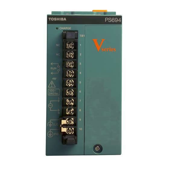
Page 38: Chapter 2 Installation
Chapter 2 Installation Wiring of the power supply PS694 RUN signal contact output 100-240VAC input ∼ PS693 24V output 100-240VAC input ∼ *1 Line filter ground (LG) Power supply *2 Frame ground (FG) Connected to base unit. See ‘2.4 Grounding’ +... - Page 39 Fasten the terminal covers securely to the terminals when wiring is finished. Exposed parts can cause electrocution. Always ground the model 2000. Failing to ground the unit can cause electrocution or malfunction. Connect to rated power supply.
-
Page 40: Connector Connection
Chapter 2 Installation 2.6 Connector Connection Connect each connector to the peripheral device as described below. • Turn off the power of the main unit and peripheral device when connecting peripheral devices. Connecting with the power on may cause injury or burn. •... -
Page 41: Handling
(1) Turn on the AC power to the power supply module. (2) Turn on the power of the peripheral devices (CD-ROM drive connected through PC card, etc.) connected to C2. (3) Turn on the model 2000 main unit. (4) Turn on the I/O module and external load power. 3.1.2 Turning Off the Power Turn off the power in the reverse order of the power on procedure. -
Page 42: Power Off With Windows
If a power supply is turned off without shutdown of Windows, the data in a hard disk is destroyed and it may be unable to reboot. Model 2000 is supporting the automatic shutdown of Windows, and the power supply off-sequence. If the power supply module of exclusive use is used, the shutdown of Windows can be performed without carrying out operation of a mouse and a keyboard. - Page 43 Important • If the running application cannot be terminated normally for some reason or other, Windows is forcibly terminated subject to the completion waiting time set with the RAS driver. In this case, the file data of application or Windows may be destroyed. Fully confirm application operation in advance that it is free of problems.
-
Page 44: Power Supply Module Ps691 With Ups I/F
Chapter 3 Handling 3.1.5 Power Supply module PS691 with UPS I/F UPS turns off secondary side power supplies in timer setting of UPS. A timer should set up sufficient time for shutdown of Windows. Power Supply Module PS691 Conversion circuit Main circuit W indows Shutdown... -
Page 45: About The Hard Disk
Do not disassemble. Failure to do so can cause malfunction of the drive. Important • Toshiba will not be responsible for the content of the hard disk regardless of the cause of failure or error. Please backup your data to guard against accidents. -
Page 46: About The External Fdd
Chapter 3 Handling 3.3 About the External FDD An external floppy disk drive is necessary if you must install OS or application programs from floppy disks or save data to floppy disks. In general, a floppy disk drive has an access lamp in front as shown at right. This lamp flashes when the drive is being accessed. - Page 47 3.3 About the External FDD [Write Protecting a Floppy Disk] To prohibit write Slide the write protect tab to the outside as shown in (1). To enable write Slide the write protect tab to the inside as shown in (2). In either case, slide the write protect tab until it clicks Write protect tab Shutter...
-
Page 48: About The Pc Card
Chapter 3 Handling 3.4 About the PC Card Two PC Cards Standard TYPE I/II (3.3V, 5V) PC cards can be inserted in the PC card slot of the C2. Or, one TYPE III PC card can be inserted when the left and right slots are combined. -
Page 49: Installation
3.4.1 Installation (1) Press the eject button of the PC card slot until the eject button pops out. (2) Press the eject button once more. The dummy card ejects. (3) Remove the dummy card. Store the dummy card in a safe place. (4) Check the direction and insert the PC card. -
Page 50: Removal
Chapter 3 Handling 3.4.2 Removal (1) Press the eject button of the PC card slot until the eject button pops out. (2) Press the eject button once more. The card ejects. (3) Hold the card firmly and pull. (4) Insert a dummy card. Computer module C2PU37 User’s Manual... -
Page 51: Maintenance
Chapter 4 Maintenance 4.1 Daily Inspection The following items should be inspected daily in order to maintain normal system operation and prevent unnecessary trouble from occurring. Item Check the LED in front of the power module. Check the LED at the front of the C2 module. -
Page 52: Periodic Maintenance
Environment Battery related • Do not attempt to disassemble, modify, or repair. This can cause electrocution, fire, or injury. Contact the Toshiba service desk for repair. Inspection Description Power supply voltage (measure at the power supply terminal of the module) -
Page 53: Replacement Timing Of Major Parts
Replacement Timing of Major Parts Listed below are the product life of major components. Periodically replace parts using this table as reference. Contact your Toshiba service desk for information concerning the price and ordering method of replacement parts. Product life of major components... -
Page 54: Replacing The Hard Disk Drive
Chapter 4 Maintenance 4.4 Replacing the Hard Disk Drive The main unit is equipped with one 2.5 inch hard disk drive in the HDD pack. The HDD pack replacement procedure is as follows: Important • Be careful not to exert excessive shock to the HDD pack. •... -
Page 55: Ras Function
Chapter 5 RAS Function RAS function (Reliability, Availability, Serviceability) represents the function which increases the operating performance of the C2. C2 is equipped with RAS hardware and RAS support software to facilitate the use of RAS functions. Persons in charge of design, operation, or maintenance of the C2 should have sufficient knowledge of these function in order to be ready in case of trouble. -
Page 56: Ras Function Overview
Chapter 5 RAS Function 5.1 RAS Function Overview The RAS hardware and software provide the following functions. 5.1.1 RAS Hardware Internal diagnosis Power ON/OFF function Reset function Interrupt output function RAS memory function 5.1.2 RAS Support Software This section provides a general description of the RAS support software. Refer to the "Computer module C2/C3 Windows User’s Manual (6F8C0894)"... -
Page 57: Hardware Processing Ras Functions
5.2 Hardware Processing RAS Functions 5.2.1 WDT Circuit and Hardware Reset The WDT circuit issues an NMI to the main unit when the WDT counter is not reset within a certain interval (WDT monitoring interval). The WDT monitoring interval can be set up to 500ms x 255 (approximately 2 minutes) in 500ms units. - Page 58 Chapter 5 RAS Function [NMI events] NMI events are the following: • power off • WDT timeout • Pressing of the INZ switch An NMI signal is sent to the main unit when any one of these events occur. An NMI event is latched inside the RAS board and held until it is processed by the RAS support software.
-
Page 59: Hardware Setup
Chapter 6 Hardware Setup The C3 hardware can be set from the BIOS screen. Normally, the setting need not be changed. Do not change the setting unnecessarily. If it is set incorrectly, the hardware may be damaged. If you inadvertently changed it incorrectly, you must change it back to the correct setting. -
Page 60: Setting The Bios
Chapter 6 Hardware Setup 6.1 Setting the BIOS The method of displaying the BIOS screen and the displayed content (default value) are shown below. Check the content before using or when there is an abnormal condition. Important • Do not enable the suspend function when using the WDT function. This may cause a mal-function. - Page 61 F1 Help ↑↓ Select Item Esc Exit ←→ Select Menu Enter Select ▼Sub-Menu F10 Save and Exit 6F8C1111 Phoenix BIOS Setup Utility Boot Exit [ XX:XX:XX ] Item Specific Help [ XX/XX/2000] [Disabled] [DISKのメーカ型式] [None] [None] 640 KB XXXXXX KB [Enabled]...
- Page 62 Chapter 6 Hardware Setup Main Advanced + Removable Devices Legacy floppy Drives + Hard Drive (DISK Maker/Type) bootable Add-in cards CD-ROM Drive F1 Help ↑↓ Select Item Esc Exit ←→ Select Menu Enter Select ▼Sub-Menu F10 Save and Exit Main Advanced Exit Saving Changes Exit Discarding Changes...
- Page 63 Main Primary Master [ DISK Maker/Type] Type: Multi-Sector Transfers LBA Mode Control 32 Bit I/O Transfer Mode F1 Help ↑↓ Select Item Esc Exit ←→ Select Menu Enter Select▼Sub-Menu F10 Save and Exit Main Primary Slave/Secondary Master [None] Type: Multi-Sector Transfers: LBA Mode Control: 32 Bit I/O Transfer Mode:...
- Page 64 Chapter 6 Hardware Setup Serial port A Serial port B Parallel port Floppy disk controller Base I/O address F1 Help ↑↓ Select Item Esc Exit ←→ Select Menu Enter Select▼Sub-Menu F10 Save and Exit 8-bit I/O Recovery: 16bit I/O Recovery: Enable memory gap: ECC Config: SERR signal condition:...
-
Page 65: A Q&A
Appendix A Q&A Sometimes, the device does not function as you expected or you may not know what to do next. Read this section before you suspect that the device is faulty. If an error message appears while using an operating system command, refer to the operating system manual. -
Page 66: The Mouse Does Not Work
Appendix A Q&A Screen display is improper. Symptom Nothing is displayed. Screen display is distorted, size or position is improper. No character is entered when a key is pressed. Symptom Unable to enter from the keyboard. There is no response from any key. - Page 67 Application program cannot be used Symptom Application program does not work as expected. Application program does not run. The floppy disk drive cannot be used Symptom FDD lamp does not go off. The floppy disk cannot be used Symptom An error message "Write protected"...
- Page 68 Appendix A Q&A Television and radio interference appears Symptom There is TV and radio interference. In case of trouble or malfunction Symptom There is abnormal smell or heat. Trouble or malfunction has occurred. If the problem is still not solved If you still cannot determine the cause of trouble, contact the service desk.
-
Page 69: B Device Specifications
CRT interface Analog RGB LAN interface Ethernet:10base-T/100base-Tx 1ch. (RJ45) PC card CARD-BUS/PCMCIA TypeII 2slots TOSHIBA integrated V series model 2000 station bus I/F controller V series model 2000 G2I/O module I/F Keyboard PS/2, 106 key (OADG specification) Mouse PS/2, 2 button... - Page 70 Appendix B Device Specifications Models Product Code GC2PU37ES GC2PU37GS Memory Windows 2000 128MB Windows 2000 256MB Auxiliary storage HDD 30GB HDD 30GB Computer module C2PU37 User’s Manual...
-
Page 71: Interface Specifications
B.2 Interface Specifications B.2.1 RGB Interface D-SUB female B.2.2 Serial Interface (RS-232C) [Remark] For the C2, the 17JE series by DDK Electronics is recommended for the cable side D-SUB connector. 6F8C1111 (Note) I/Os are input/output as viewed from this device. Pin no. -
Page 72: Keyboard And Mouse Interface
Appendix B Device Specifications B.2.3 Keyboard and Mouse Interface mini DIN female B.2.4 USB Interface B.2.5 Ethernet Interface 10/100baseT Ethernet socket (Note) I/Os are input/output as viewed from this device. Pin no. Signal name DATA Unused CLOCK Unused (Note) I/Os are input/output as viewed from this device. Pin no. -
Page 73: Fdd Interface
B.2.6 FDD Interface (Note) I/Os are input/output as viewed from this device. Pin no. SIDE1 SEL READ DATA WRITE DATA DENSITY SEL RESERVE READY DRIVE SEL INDEXL 6F8C1111 Half pitch female Signal name Pin no. Signal name WRITE PROTECT* TRACK 00* WRITE GATE* STEP* DIRECTIOEN*... -
Page 74: Pcmcia Card Slot
Appendix B Device Specifications B.2.7 PCMCIA card slot PC Card I/O Pin no. Function PC Card Pin no. ATA Function CDD3 CDD3 CDD4 CDD4 CDD5 CDD5 CDD6 CDD6 CDD7 CDD7 -CE1 -CS0 CA10 N.C. CA11 N.C. -CS1 N.C. CWA13 N.C. CA14 N.C. - Page 75 Integrated Controller Vseries model 2000 Computer module C2PU37 User’s Manual 1st edition INDUSTRIAL AND POWER SYSTEMS & SERVICES COMPANY ELECTRICAL APPARATUS & MEASUREMENT DIV. 1-1, Shibaura 1-chome, Minato-ku, Tokyo 105-8001, Japan Tel.:+81-3-3457-4737 TOSHIBA Corporation 2004 ⃝ All Rights Reserved. 14th May 2004 Fax.:+81-3-3457-8386...
- Page 76 6F8C1111...
Need help?
Do you have a question about the 2000 and is the answer not in the manual?
Questions and answers