Table of Contents
Advertisement
Quick Links
CAMERA CONTROL UNIT
IK-TF7U
FCC NOTICE
This equipment has been tested and found to comply with the limits for a Class A digital device, pursu-
ant to Part 15 of the FCC Rules. These limits are designed to provide reasonable protection against
harmful interference when the equipment is operated in a commercial environment. This equipment
generates, uses, and can radiate radio frequency energy and, if not installed and used in accordance
with the instruction manual, may cause harmful interference to radio communications. Operation of this
equipment in a residential area is likely to cause harmful interference in which case the user will be
required to correct the interference at his own expense.
USER-INSTALLER CAUTION: Your authority to operate this FCC verified equipment could be voided
if you make changes or modifications not expressly approved by the party responsible for compliance
to Part 15 of the FCC Rules.
This Class A digital apparatus complies with Canadian ICES-003.
Cet appareil numérique de la classe A est comforme à la norme NMB-003 du Canada.
Following information is only for EU-member states:
The use of the symbol indicates that this product may not be treated as household waste.
By ensuring this product is disposed of correctly, you will help prevent potential negative con-
sequences for the environment and human health, which could otherwise be caused by inap-
propriate waste handling of this product. For more detailed information about the takeback
and recycling of this product, please contact your supplier where you purchased the product
or consult.
This manual is made from 100% recycled paper.
INSTRUCTION MANUAL
For Customer Use
Enter below the Serial #
which is located on the
bottom of the cabinet. Retain
this information for future
reference.
Model #:
Serial #:
IK-TF7U
Advertisement
Table of Contents

Related Manuals for Toshiba IK-TF7U


Summary of Contents for Toshiba IK-TF7U
-
Page 1: (A) Instruction Manual
INSTRUCTION MANUAL CAMERA CONTROL UNIT IK-TF7U For Customer Use Enter below the Serial # which is located on the bottom of the cabinet. Retain this information for future reference. Model #: IK-TF7U Serial #: FCC NOTICE This equipment has been tested and found to comply with the limits for a Class A digital device, pursu- ant to Part 15 of the FCC Rules. -
Page 2: Safety Precautions
SAFETY PRECAUTIONS Safety icons This manual contains safety instructions that must be observed in order to avoid potential hazards that could result in personal injuries, damage to your equipment, or loss of data. These safety cautions have been classified according to the seriousness of the risk, and the icons highlight these instructions as follows: Indicates a potentially hazardous situation which, if not avoided, could result in death or serious injury. -
Page 3: Protection Of Personal Information
5. Repairs or modifications made by the user or caused to be made by the user and carried out by an unauthorized third party. 6. Notwithstanding the foregoing, Toshiba’s liabilities shall not, in any circumstances, exceed the purchase price of the product. -
Page 4: Table Of Contents
Copyright and Right of Portrait There may be a conflict with the Copyright Law and other laws when a customer uses, displays, distributes, or exhibits an image picked up by the camera without permission from the copyright holder. Please also note that transfer of an image or file covered by copyright is restricted to use within the scope permitted by the Copyright Law. -
Page 5: Cautions On Use And Installation
( 3 ) Trigger Pulse Specifications ....32 ( 2 ) Vertical Output Waveform Timing Chart ... 33 ( 4 ) External HD/VD Input Phase 10. SPECIFICATIONS ........34 Specifications .......... 32 11. EXTERNAL APPEARANCE DIAGRAM ..35 9. OUTPUT WAVEFORM TIMING CHART ..... 33 12. -
Page 6: Names And Functions
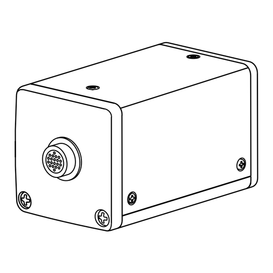
3. NAMES AND FUNCTIONS DC IN 12V terminal Camera cable for ‘IK-TF7H’ terminal DISP button MENU UP button (AWB) DATA UP (AWB) button DISP MENU DATA DC IN 12V DATA DOWN button PAGE MENU DOWN button DIGITAL terminal PAGE button [ Front ] [ Rear ] [ Bottom ]... -
Page 7: Connection
4. CONNECTION 4. 1 Standard Connection Camera control unit Lans Cable Camera cable (option) (option) for IK-TF7U IK-TF7U (option) Monitor Frame grabber board, IK-TF7H image process (option) equipment etc. DC IN 12V When connection the frame grabber board, image process equipment, etc... -
Page 8: Operation
5. OPERATION A camera head “IK-TF7H” is supposed to be connected to this camera control unit from this section. 1 Refer to the item " 4. CONNECTION", connect each equipment correctly. 2 Turn on the connected equipment and the power source of the camera. 3 When using the camera for the first time and when replacing the camera cable and the camera head, be sure to operate the ABB adjustment refer to the item "Automatic Black Barance". - Page 9 1 AWB (Automatic white balance) • Set the MODE to AWB on the WHT BAL menu. Perform the C.TEMP (color temperature conversion) setting, if necessary. (Refer to the item "7.2 (3) WHT BAL (White balance)".) 3200K : Appropriate for indoor shooting. 5600K : Appropriate for outdoor shooting.
-
Page 10: Gain
5. 3 Gain When the image is dark even if the lens iris is open, change the gain (video gain) to get the proper video level. For the gain adjustment of the unit, MANU (Manual) and OFF (0 dB) modes are provided. Select the mode on the GAIN menu. -
Page 11: Items Controlled By The Screen Display
6. ITEMS CONTROLLED BY THE SCREEN DISPLAY Preset value Item Available selections (Factory setting) MODE MANU, SS, E. TRG MANU E. TRG 1P SNR, 1P SR, PW SNR, PW SR, RR 1P SNR MANU speed OFF, 1/100s, 1/250s, 1/500s, 1/1000s, 1/2000s, 1/4000s, 1/10000s, 1/25000s, 1/50000s, 1/1000000s Syncro. -
Page 12: Mode Setting By The Screen Display
7. MODE SETTING BY THE SCREEN DISPLAY Various settings can be controlled on the unit by using the on screen menu displayed on the monitor. The contents once set are memorized even if the power source is turned off, so it is unnecessary to set again when using the unit next time. -
Page 13: Menus
7. 2 Menus • Select the menu to change the setting by referring to the item "7.1 Using the Menus".) • When the [MENU UP], [MENU DOWN] buttons are pushed, the " " on the screen moves up and down. Move the "... -
Page 14: (1. 1) Changing The Setting In
(1. 1) Changing the setting in MANU mode Move up down Select the desired by pushing value by pushing MENU UP, DOWN DATA UP, DOWN • Sutter mode MANU, SS, E.TRG -- SHUTTER -- • Sutter speed setting OFF, 100 (1/100s), 250 (1/250s), 500 (1/500s) MODE MANU 1000 (1/1000s), 2000 (1/2000s), 4000 (1/4000s) -
Page 15: (1. 2) Changing The Setting In
(1. 2) Changing the setting in SS (synchro. scan) mode Move up down Select the desired by pushing value by pushing MENU UP, DOWN DATA UP, DOWN -- SHUTTER -- MODE • Sutter mode MANU, SS, E.TRG • Synchro. scanning setting PART •... -
Page 16: (1. 3) Changing The Setting In
(1. 3) Changing the setting in E.TRG mode The E.TRG has five modes; 1P SNR, 1P SR, PW SNR, PW SR, RR. First move the " " to MODE and select E. TRG, then move the " " to E.TRG and select the desired E.TRG mode. -
Page 17: (1. 3. 2) Changing The Setting In 1P Sr Mode
(1. 3. 2) Changing the setting in 1P SR mode Move up down Select the desired by pushing value by pushing MENU UP, DOWN DATA UP, DOWN • Sutter mode MANU, SS, E.TRG -- SHUTTER -- • E.TRG mode 1P SNR, 1P SR, PW SNR, PW SR, RR MODE E.TRG E.TRG... -
Page 18: (1. 3. 3) Changing The Setting In
(1. 3. 3) Changing the setting in PW SNR mode Move up down Select the desired by pushing value by pushing MENU UP, DOWN DATA UP, DOWN • Sutter mode MANU, SS, E.TRG -- SHUTTER -- • E.TRG mode MODE E.TRG 1P SNR, 1P SR, PW SNR, PW SR, RR E.TRG... -
Page 19: (1. 3. 4) Changing The Setting In
(1. 3. 4) Changing the setting in PW SR mode Move up down Select the desired by pushing value by pushing MENU UP, DOWN DATA UP, DOWN • Sutter mode MANU, SS, E.TRG -- SHUTTER -- • E.TRG mode MODE E.TRG 1P SNR, 1P SR, PW SNR, PW SR, RR E.TRG... -
Page 20: ( 2 ) Gain (Video Gain)
( 2 ) GAIN (Video gain) When the image is dark even if the lens iris is open, change the gain (video gain) to get the proper video level. For the gain adjustment of the unit, MANU (Manual) and OFF (0dB) modes are provided. 1 MANU (Manual gain) Gain adjustment is performed on the GAIN menu. -
Page 21: ( 3 ) Wht Bal (White Balance)
( 3 ) WHT BAL (White balance) WHT BAL has two modes; AWB, MANU. Move the " " to MODE, push the [DATA UP], [DATA DOWN], and select one of the two modes between AWB and MANU. (3. 1) Changing the setting in AWB (Automatic White Balance) mode Move up down Select the desired by pushing... -
Page 22: 4 ) Process
( 4 ) PROCESS • Gamma Correction (GAMMA) Select either OFF or ON of Gamma Correction. • Master Pedestal (M. PED) Adjust the Pedestal level of each RGB. • R Pedestal (R. PED) Adjust the Pedestal level of Red. • B Pedestal (B. PED) Adjust the Pedestal level of Blue. -
Page 23: (4. 5) Changing The Shading
(4. 5) Changing the shading correction mode 1 Move the " " to SHAD. by pushing [MENU UP], [MENU DOWN] buttons. 2 Select the SHAD. by pushing [DATA UP], [DATA DOWN] buttons. Note: The alignment value for shading is fixed to "0" when selecting SHAD. OFF. MANU is not dis- played in the menu. -
Page 24: 7 ) Returning To Factory Settings
( 7 ) Returning to factory settings All the settings can be returned to the factory default status (preset status). (1) If characters are displayed on the screen, press the [DISP] button to disable the character display. (2) Push [MENU DOWN] and [DATA DOWN] buttons simultaneously for approx. 1 second. (3) The preset operation starts. -
Page 25: Trg (External Trigger)
7. 4 E. TRG (External trigger) Charge begins to accumulate after the trigger input to CC1 of the DIGITAL terminal, and 1 frame images are output. There are four modes: 1P SNR, 1P SR, PW SNR, PW SR. ( 1 ) 1P SNR (1 Pulse Trigger Sync Non Reset) Charge begins to accumulate after the trigger input to CC1 of the DIGITAL terminal, and 1 frame images are output. -
Page 26: ( 2 ) 1P Sr (1 Pulse Trigger Sync Reset)
( 2 ) 1P SR (1 Pulse Trigger Sync Reset) Charge begins to accumulate after the trigger input to CC1 of the DIGITAL terminal, the vertical sync signal is reset and frame images are output. (2. 1) 1 Pulse Trigger SYNC-RESET Picture Output Timing Negative polarity mode Trigger* Positive polarity mode... -
Page 27: ( 3 ) Pw Snr (Pulse Width Trigger Sync-Non Reset)
( 3 ) PW SNR (Pulse width trigger SYNC-NON RESET) The trigger input to CC1 of the DIGITAL terminal develops 1 frame images. (3. 1) Pulse Width Trigger SYNC-NON RESET Picture Output Timing Negative polarity mode Trigger* Positive polarity mode About 7 s About 1 s Exposure period*... -
Page 28: ( 4 ) Pw Sr (Pulse Width Trigger Sync-Reset)
( 4 ) PW SR (Pulse width trigger SYNC-RESET) The trigger input to the CC1 of the DIGITAL terminal develops 1 frame images. (4. 1) 1 Pulse Width Trigger SYNC-RESET Picture Output Timing Negative polarity mode Trigger* Positive polarity mode About 1 s About 7 s Exposure period*... -
Page 29: ( 5 ) Rr (Reset Restart)
( 5 ) RR (Reset restart) Input of an external reset-restart signal (CC4 of the DIGITAL terminal: External VD input) permits one screen of information to be output at an arbitrary timing. (5. 1) Long Term Exposure When a sufficient sensitivity is not obtained with the normal operation conditions or capturing the trial of a moving subject is desired, the reset-restart function allows high-sensitivity images by extending the exposure time. -
Page 30: Partial Read
7. 5 Partial Read ( 1 ) Partial Scanning OFF (All pixels scanning) In this mode, all pixels independent signal from the DIGITAL connector is output each 1/29.2 second (Line order output). Video interval image 1/29.2s (796H) ( 2 ) Partial Scanning ON In this mode, the pixel signal of the vertical center portion from the DIGITAL connector is output. -
Page 31: External Sync
7. 6 External Sync When using the unit with an external sync signal, input HD and VD to CC3 and CC4 of the DIGITAL terminal. When the external sync signal is input, the camera automatically switches its sync from the internal sync to the external sync. -
Page 32: Input Output Signal Specifications
8. INPUT OUTPUT SIGNAL SPECIFICATOINS ( 2 ) VD Input Specifications ( 1 ) HD Input Specifications 2.0 s 5.0 s ( 3 ) Trigger Pulse Specifications (Positive polarity mode) More than 2 s (Negative polarity mode) More than 2 s ( 4 ) External HD/VD Input Phase Specifications External HD rising edge... -
Page 33: 2 ) Vertical Output Waveform Timing Chart
9. OUTPUT WAVEFORM TIMING CHART ( 1 ) Horizontal Output Waveform Timing Chart One horizontal scan interval 1270 clk (43.05 s) LVAL, DVAL 246 clk 33.9 ns (8.34 s) 164 clk 29 clk 3 clk 40 clk output signal 5 clk Optical black Horizontal transfer Dummy... -
Page 34: 4 ) External Hd/Vd Input Phase 10. Specifications
10. SPECIFICATIONS Power supply 12V DC±10% Power consumption Approx. 6.1W Pick-up system RGB, 3CCD Image sensor 1/3inch All pixels CCD (Effective pixels Horizontal : 1034, Vertical : 779) Scanning System Progressive scan Video output pixels Horizontal pixels : 1024, Vertical : 768 Pixel clock frequency 29.5MHz Sync signal frequency... -
Page 35: External Appearance Diagram
11. EXTERNAL APPEARANCE DIAGRAM Unit : mm [inch] 4.8 [0.19] 44 [1.73] 78 [3.07] [0.25] 12 [0.47] [0.21] 4.8 [0.19] 2-M2 4.5 [0.18] 56 [2.20] 4-M3 Depth 3 19.2 [0.76] * inch = mm/25.4 4-M2 Depth 3 24.5 [0.96] [0.98] 12. - Page 36 Limited Warranty – TOSHIBA CCD Camera The Imaging Systems Division of Toshiba America Information Systems, Inc. ("ISD") makes the following limited warranties with regard to this CCD Camera ("Product"). These limited warranties extend to the Original End-User ("You[r]"). One (1) Year Limited Warranty of Labor and Parts ISD warrants that this Product will perform in accordance with specifications for a period of one (1) year from the date of purchase by the Original End-User.
Need help?
Do you have a question about the IK-TF7U and is the answer not in the manual?
Questions and answers