Craftex CX Series User Manual
6” helical jointer
Hide thumbs
Also See for CX Series:
- User manual (49 pages) ,
- Manual (42 pages) ,
- Owner's manual (35 pages)
Table of Contents
Advertisement
Quick Links
Advertisement
Table of Contents

Related Manuals for Craftex CX Series


Summary of Contents for Craftex CX Series
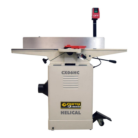
- Page 1 MODEL CX06HC 6” HELICAL JOINTER USER MANUAL Version 1...
-
Page 2: Table Of Contents
TABLE OF CONTENTS General Safety Instructions ....................3 Machine Specifications ......................4 Identification………………………………………….…………………………..………....5 Power Supply……………………………………………………………………..………………… 6 Plug and Grounding Requirements…………………………………………..…………………... 7 Set Up……………………………………………………………………………..…………………. 8 Inventory………………………………………………………………………..……………………. 9 Locking Foot Pedal & Mounting the Jointer……………………..……………………...……….9 & 10 V – Belt……………………………………………………………………..…………………………11 … Carriage Mounting Bracket……………………………………………….……... -
Page 3: General Safety Instructions
GENERAL SAFETY INSTRUCTIONS Extreme caution should be used when operating all power tools. Know your power tool, be familiar with its operation, read through the owner’s manual and practice safe usage procedures at all times ALWAYS read and understand the router bits, shaper heads, blades, knives user manual before operating the or making other adjustments or repairs. -
Page 4: Machine Specifications
CX06HC MACHINE SPECIFICATIONS Table Size……………………………………….….………………………………………………………6” W x 46” L Table Height......................32-1/2” Overall length……………………………….….…………………….………………………………………………..46” Overall Width……………………………..………………….………………………………………………….27-1/2” Shipping weight……………….………….……………….……………………………………………………….80 kg Net Weight………………………………….……………….……………………………………………………….74 kg Box 1 Size…………………………….…….………………….………………………………….48-1/2” x 21” x15” Box 2 Size………………………………….….……………….……………………20-1/2” x 15-3/4” x 28-3/4” Foot Print…………………………………..…………………….……………………………………….18” x 13-1/2” Maximum Depth of cut…………………..…………………………………………………………….………..1/8” Maximum Width of Cut……………………..………………………………………....……………………6”... -
Page 5: Identification
Identification A. Outfeed table B. Fence C. Cutterhead Guard D. Fence Lock E. Fence Adjustment Knob F. Fence Tilt Handle G. Control Panel H. Infeed Table I. Infeed Table Lever J. Locking Foot Pedal K. Depth Scale L. Dust Port M. -
Page 6: Power Supply
on an undersized circuit. To help avoid POWER SUPPLY these issues insure you are connected to a circuit that meets the specified AVAILABILITY OF POWER circuit requirements for this piece of Before Installation of this machine you machinery. will need to consider the proximity of your power supply circuit. -
Page 7: Plug And Grounding Requirements
3. If you choose to connect to a shared circuit where more than machine may be running at a time please consult with a qualified electrician to insure the circuit is properly sized for safe operation. PLUG AND GROUNDING REQUIREMENTS This machine must be grounded so that Figure 1 in the event of certain malfunctions it will... -
Page 8: Setup
NOTE: WARNING! 1. We recommend that you do not use This Machine weighs 80kg. DO NOT an extension cord with this machine. overexert yourself while unpacking or moving your machine. GET ASSISTANCE! Also the longer the extension cord the greater the possibility of voltage drop Tools Required for Setup causing the motor to work harder under powered which in turn will cause it to... -
Page 9: Inventory
Phillips Head Screws M5-.8 x 15 5 INVENTORY Flat Washers M5 Inventory Check for the following items packed in the two boxes you received. In the event that any nonproprietary parts are missing (e.g. a nut or a washer), we will replace them, or for the sake of expediency, replacements can be obtained at your local hardware store... - Page 10 Hex Nuts M10-1.5 Hex Bolt M8-1.25 x 50 Flat Washer 8mm Tools Required 17mm Wrench 17mm Socket Wrench Figure D 13mm Wrench 4. Install the two M10-1.5 x 55 Hex Bolts, Level flat washers and nuts through the front of the locking foot pedal assembly as Installing the locking foot pedal: shown in (Fig.
-
Page 11: Belt
Tools required: 8mm Hex Key Extra Person for Lifting Help CAUTION! The jointer is heavy. Get assistance when lifting it in place onto the cabinet. Mounting the jointer: 1. Remove the back cabinet cover Figure G 2. With the help of an assistant, lift the jointer onto the cabinet V-Belt 3. -
Page 12: Carriage Mounting Bracket
Figure H Figure I 3. Carefully allow the motor to slide Carriage Mounting Bracket downward, tensioning the V-belt with the weight of the motor. Components & Hardware Required: 4. Looking from the top, sight down the V- Carriage Mounting Bracket belt and pulleys and check that the Cap Screws M8-1.25 x 60 pulleys are parallel and aligned with... -
Page 13: Assembling The Fence
2. Tighten the carriage mounting bracket to the jointer table with the cap screws, lock washers & flat washers supplied. (Fig. K) Figure L Assembling the Fence Components & Hardware Required: Figure K Fence Assembly Assembling the Fence Carriage Cap Screws M8-1.25 x 25 Lock Washers 8mm Components &... -
Page 14: Cutterhead Guard
2. Place the cutter head guard into the mounting hole on the casting of the infeed table. Fig P. Ensuring that the cutterhead guard shaft fits over the pin that is inside the grey spring knob barrel (hidden from View). Figure N Cutterhead Guard CAUTION! -
Page 15: Power Switch Install
Figure Q Figure R Dust Port Installation Power Switch Install Components & Hardware Required: Components & Hardware Required: Dust Port Power Switch and Support Arm Phillips Head Screws M5-.8 x 15 Cap Screws M8-1.25 x 25 Flat Washers 5mm Flat Washers 8mm Tools required: Tools required: Phillips Head Screwdriver... - Page 16 motor. Then secure the loose cords with the hold downs shown in (Fig. T) Figure U 3. Thread the infeed lever into the hole as shown in (Fig.V) then tighten the locknut with the 19mm wrench Figure T Table Controls Installation Components &...
-
Page 17: Replacing Carbide Inserts
To set the outfeed table height: table height with the handwheel until the straightedge just touches an insert at its 1. DISCONNECT JOINTER FROM POWER highest point of rotation. SUPPLY! 5. Lock the outfeed table, re-install the 2. Move the cutterhead guard out of the cutterhead guard, and close the rear access way or remove it, and open the rear panel. - Page 18 To rotate or change a carbide insert: Test Run 1. Disconnect JOINTER from power! WARNING! Long hair, loose clothing and jewelry can 2. Move the cutterhead guard out of the get caught up in the moving parts of way, or remove it. machinery and result in serious injury.
-
Page 19: Operations
problems in the shipping process we Infeed Table Adjustment recommend that you verify the following to ensure the best possible results from your Before any cut the proper infeed table machine. adjustment must be made to safely and efficiently use this jointer. DO NOT set the Depth Scale calibration infeed table depth greater than 1/16”... -
Page 20: Stock Inspection
Remove foreign objects from the Note: workpiece. Always check your Adjust the infeed table stops to return the workpiece for foreign objects such as table height to the same height every time nails and staples. Ensure that your by loosening the lock nuts and adjusting the workpiece is free of dirt that may set screws. -
Page 21: Squaring Stock & Surfacing Planing
Squaring Stock Squaring stock is accomplished by performing the following four steps in the order listed. 1. Surface plane on the jointer – The concave face of the workpiece is Surface Planing surface planed flat with the jointer. The purpose of surface planing is to make one surface of a workpiece flat ref. -
Page 22: Edge Jointing
2. Set the depth of cut required. (1/32” for step toward squaring rough or warped wood. surface planing, for hardwoods and (Fig.GG & HH) wide workpieces use a smaller DOC. 3. Set the fence at 90 degrees. 4. I you have a cupped or warped workpiece, place the concave side down on the infeed table (Fig. -
Page 23: Bevel Cutting & Rabbet Cutting
6. Feed workpiece over cutterhead, keeping a constant pressure on the workpiece against the table and the fence. (Fig. GG) Note: When your leading hand gets within 4” of the cutterhead. Lift it up and over the cutterhead and place it on Figure JJ the portion of the workpiece that is now on the outfeed table. - Page 24 Note: When your leading hand gets within 4” of the cutterhead. Lift it up and over the cutterhead and place the push block on the portion of the workpiece that is now on the outfeed table. Now, focus your pressure on the outfeed end of the workpiece while feeding, and repeat the same process with your trailing hand when it gets within 4”...
-
Page 25: Maintenance & Service
There is no lubrication regimen necessary Note: for this machine as all bearings are sealed, When your leading hand gets within simply leave them alone until they need to 4” of the cutterhead. Lift it up and be replaced. DO NOT lubricate the fence over the cutterhead and place the assembly or table ways. -
Page 26: Setting The Fence Stops
4. Using a screwdriver, adjust the scale 3. Adjust the 45 deg. inward fence stop pointer exactly to “0” (zero) (Fig.NN) nut until it makes contact with the back of the fence bracket, then re- tighten the jam nut from Step 2 and recheck. -
Page 27: Adjusting The Gibs
Setting the 45 deg. Outward Fence stop: Adjusting the Gibs 1. Flip the 90 deg. swing stop out of The purpose of the table gibs is to eliminate the way (Fig. SS) excessive play in the table movement. They also control the smoothness of the table 2. - Page 28 2.) Symptom Electrical Components Fuses or circuit breakers blow Possible Cause Short circuit in line cord or plug. Possible Solution Repair or replace cord or plug for damaged insulation and shorted wires. Figure VV 3.) Symptom Motor fails to develop full power (output of motor decreases rapidly with increase in voltage at motor terminals) Possible Cause...
- Page 29 Adjust fan cover mounting position, tighten fan, or shim fan cover. III. Replace V-belts. Possible Cause Motor overloaded during operation. 8.) Symptom Short circuit in motor or loose Vibration when running or cutting connections. III. Circuit breaker tripped. Possible Cause Loose or damaged blade.
- Page 30 Adjust one of the nicked knives Cutting sideways, or replace knives. III. Slow the feed rate down. 1.) Symptom Take a smaller depth of cut. (Always Excessive snipe (gouge in the end of the reduce cutting depth when surface board that is uneven with the rest of the planing or working with hard woods) cut) 4.) Symptom...
- Page 31 It may take 3 to 5 passes to achieve 7.) Symptom a perfect edge, depending on the Board edge is convex or concave after starting condition of the board and jointing the depth of cut Possible Cause 8.) Symptom Board not held with even pressure Uneven cut or breakout when rabbeting on infeed and outfeed table during cut.
- Page 32 TABLE PARTS BREAKDOWN...
-
Page 33: Parts Breakdown & Parts List
TABLE PARTS LIST Item Part Number Description Item Part Number Description PCX06HC01 Power Bit T20 Torx PCX06HC45 PLATE PCX06HC02 Insert 14x14x2mm PCX06HC46 TORSION SPRING PCX06HC03 Torx Screw PCX06HC47 PCX06HC04 PULLEY PCX06HC48 RETAINER PCX06HC05 BEARING BLOCK RIGHT PCX06HC49 BUTTON HD CAP SCR M4.7 X 18 PCX06HC06 BALL BEARING 6203ZZ PCX06HC50... - Page 34 FENCE PARTS BREAKDOWN...
- Page 35 Fence Parts List Item Part # Description Item Part # Description 112 PCX06Z112 SCREW - CAP M6-1.0 X 20 PCX06Z88 FENCE 113 PCX06Z113 SCREW - PHLP HD M6-1.0 X 12 PCX06Z89 LEVER ROD 114 PCX06Z114 WASHER - LOCK 8MM PCX06Z90 BALL KNOB 115 PCX06Z115 GUARD PCX06Z91...
- Page 36 Base Parts Breakdown...
- Page 37 Base Parts List Item Part Number Description Item Part Number Description PCX06HC201 CABINET PCX06HC231 TAP SCREW M4 X 8 PCX06HC202 HEX NUT M8-1.25 PCX06HC232 TAP SCREW M4 X 8 PCX06HC203 FLAT WASHER 8MM PCX06HC233 SWITCH PLATE PCX06HC204 WHEEL PCX06HC234 EXT RETAINING RING 9MM PCX06HC205 SLEEVE PCX06HC235...
-
Page 38: Warranty
This warranty shall not apply to consumable products such as blades, bits, belts, cutters, chisels, punches etceteras. Craftex shall in no event be liable for injuries, accidental or otherwise, death to persons or damage to property or for incidental contingent, special or consequential damages arising from the use of our products.
Need help?
Do you have a question about the CX Series and is the answer not in the manual?
Questions and answers