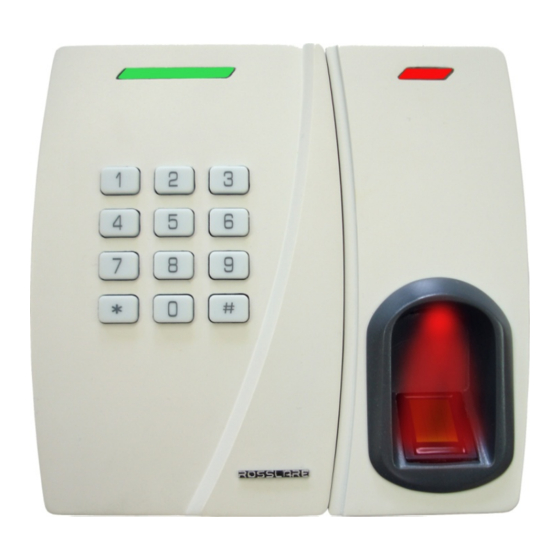
Rosslare AYC-W6500 Installation And Operation Manual
Integrated reader and controller
Hide thumbs
Also See for AYC-W6500:
- Installation and user manual (50 pages) ,
- Installation and programming manual (57 pages)

Related Manuals for Rosslare AYC-W6500


Summary of Contents for Rosslare AYC-W6500
- Page 1 AYC-W6500 Integrated Reader and Controller Installation & Operating Guide June 2008...
-
Page 3: Table Of Contents
1.3 Unpacking the Equipment.............4 1.4 Ancillary Equipment.............4 2. Technical Specifications ............5 2.1 Key Features .................6 3. Installation ................8 3.1 Mounting the AYC-W6500 ..........8 3.2 Wiring Instructions ...............9 4. Reader Functionality ............13 4.1 Modes of Operation ............13 4.2 Enrolling a Fingerprint............15 4.3 Programming the AYC-W6500 ..........16... -
Page 4: General Information
When the AYC-W6500 unit is connected to a standard access controller, then it functions as a reader. If the unit is connected to one of Rosslare's intelligent power supplies; PS- A15T/TU, PS-C15T/TU, PS-A25T/TU, or PS-C25T/TU it functions as a secured controller. -
Page 5: Reader/Controller Types
General Information Reader/Controller Types Upon power-on reset, the AYC-W6500 searches for the presence of a Rosslare PS-Ax5T/TU or PS-Cx5T/TU intelligent power supply. If the power supply is detected, then the AYC-W6500 is automatically configured as a secure access control unit. Two short beeps (one second apart) are generated on power-on reset. -
Page 6: Technical Specifications
Proximity card compatibility EM cards Card Transmit format (Reader) 26-bit Wiegand, or Clock & Data Keypad 3 x 4 Key, Backlit Keypad Transmit Format Programmable PIN code formats (Reader) LED reader status Two Tri-colored LEDs Page 5 AYC-W6500 Installation Manual... -
Page 7: Key Features
5.16" x 4.92" x 1.38" (131x125x35 mm) Weight: 270g (0.595lbs) *Measured using Rosslare proximity card (AT-14) or equivalent. Range also depends on the electrical environment and proximity to metal. 2.1 Key Features The AYC-W6500 system includes the following key features: •... - Page 8 Comes with mounting template for easier installation • Comes with an installation kit that includes a security screw and a security screw tool Reader and Controller Features Additional features for the AYC-W6500 series include the following: Reader • Programmable keypad transmission format •...
-
Page 9: Installation
Installation Installation The AYC-W6500 is easy to install and fits all standard US and UK gang boxes. 3.1 Mounting the AYC-W6500 Before connecting the AYC-W6500, mount it on an appropriate surface. In most circumstances, the unit should be located at approximately shoulder height. -
Page 10: Wiring Instructions
If the tamper output is used, connect the purple wire to the correct input on the controller when used as reader, or to the zone input of an intruder alarm system when used as a controller. Trim and cover all unused conductors. Page 9 AYC-W6500 Installation Manual... - Page 11 This configuration is best for shielding the unit cable from external interference AYC-W6500 Figure 2: Controller Application Wiring Diagram #1 Wiring diagram #2 (below) shows the door monitor and the tamper input to an external alarm system. AYC-W6500 Installation Manual Page 10...
- Page 12 Wiring diagram #3 shows the auxiliary signal input to the external alarm system. AYC-W6500 Figure 4: Controller Application Wiring Diagram #3 The wiring diagram #4 (below) shows the wiring for the reader application. Figure 5: Reader Application Wiring Diagram #3 Page 11 AYC-W6500 Installation Manual...
- Page 13 Installation Figure 6: PC Connection Using RS-232 Cable AYC-W6500 Installation Manual Page 12...
-
Page 14: Reader Functionality
Reader Functionality Reader Functionality The AYC-W6500 series can function both as a reader and as a controller. When the unit is connected to a standard access controller, it functions as a reader. When the unit is reset and is operating as a reader, it generates one beep. - Page 15 Reader status LED flashes red Changing from Secure Mode to Normal Mode The default factory setting for Normal / Secure code is 3838. Enter the Normal / Secure code. • Reader status LED flashes green AYC-W6500 Installation Manual Page 14...
-
Page 16: Enrolling A Fingerprint
• The fingerprint reader LED flashes orange Place the user’s finger on the sensor. • The unit sounds a short beep followed by an additional three short beeps. • The fingerprint reader LED flashes red Page 15 AYC-W6500 Installation Manual... -
Page 17: Programming The Ayc-W6500
Repeat the process from the beginning. Programming the AYC-W6500 Programming of the AYC-W6500 is performed solely via the unit's keypad, using a built-in Programming Menu System. To reach the Programming Menu System, first place the AYC-W6500 into Programming Mode. - Page 18 6 - 6 digit PIN code 8 - 4-8 digit PIN code Entering Programming Mode The Programming Mode allows the user to control how the AYC-W6500 behaves and to set operation preferences. Note: It is not possible to program the unit while it is operating in Secure mode.
- Page 19 The AYC-W6500 has now returned to Normal Access Mode. Selecting the Keypad Transmission Format The AYC-W6500 can operate using any one of four different keypad transmission formats. The keypad transmission format is set in Menu 1. Follow the steps below to select the appropriate keypad transmission format that you wish to use.
- Page 20 • PIN Code 4-8 Keys – Not a valid setting Option 1: Single Key, 6-Bit Wiegand (Rosslare Format) Transmission of 4 bits with 2 parity bits added occurs after fingerprint verification, with a delay of 50 ms between each number transmitted.
- Page 21 6 Wiegand 6 bit frames, 6 digits entered. • PIN Code 4-8 Keys 4 to 7 Wiegand 6 bit frames, 4-7 keys entered. Or, 8 Wiegand 6 bit frames, 8 keys entered, followed by # key. AYC-W6500 Installation Manual Page 20...
- Page 22 Or, 8 Wiegand 6 bit frames, 8 keys entered, followed by # key.. Selecting Proximity Card Transmission Format The AYC-W6500 has two proximity card transmission formats. The card transmission format is set in Menu 2. Follow the steps below to select the appropriate Proximity Card reader transmission format you wish to use.
- Page 23 Changing the Facility Code This code is used only by PIN codes that are transmitted in multiple keys formats. It is inserted in the MSB byte of the transmitted data, one bit following the leading parity bit. AYC-W6500 Installation Manual Page 22...
- Page 24 Note: In secure mode, option 2 will turn the keypad backlight on whenever a user presents a card. System returns to Normal Access Mode. • The unit sounds three beeps. Page 23 AYC-W6500 Installation Manual...
- Page 25 LED_CTL input. When the LED_CTL input is set, the LED will turns green or the buzzer will sound. To Control the Unit via the LED_CTL Auxiliary Input: Enter Programming Mode (see Entering Programming Mode, page 36). Press “6” to enter Menu 6. AYC-W6500 Installation Manual Page 24...
- Page 26 Enabling and Disabling Fingerprint Enrollment By default, when a user presents her proximity card or enters her PIN code for the first time, the AYC-W6500 will automatically request and enroll that user's fingerprint. For increased security, it is possible to disable automatic fingerprint enrollment.
- Page 27 PIN code. • If the selected slot already has a PIN code ID but no Card ID, the Reader status LED flashes green , indicating that the controller is ready to accept a card ID AYC-W6500 Installation Manual Page 26...
- Page 28 To enter more IDs, return to step 4. Press “#” twice to exit Programming Mode. • If the second ID is invalid, the unit sounds a long beep. The AYC-W6500 will continue to wait for a valid ID to be entered. Page 27 AYC-W6500 Installation Manual...
- Page 29 Reader Functionality • If the second ID is of the same type (PIN-PIN/Card-Card), the unit sounds a short beep. The AYC-W6500 will continue to wait for a valid ID to be entered. Deleting Users Users can be deleted using the Standard and the Code Search method.
- Page 30 AYC-W6500 returns to Normal Access Mode. If the programming code is invalid, the unit sounds a long beep and the AYC-W6500 returns to Normal Access Mode. PIN Code Length / Factory Default Settings Use this command to erase all user codes, reset all operation codes to their factory settings and to specify a new PIN code length.
- Page 31 Activate the tamper sensor by removing the reader from the wall or removing the reader's case. Reconnect the reader to the power supply. You have 10 seconds to enter Programming Mode using the factory default programming code 1234 AYC-W6500 Installation Manual Page 30...
-
Page 32: Controller Functionality
Controller Functionality Controller Functionality The AYC-W6500 can function both as a reader and as a controller. If the unit is connected to a Rosslare PS-Ax5T/TU or PS-Cx5T/TU intelligent power supply, or others, it functions as a controller. This is indicated by two short beeps on power-on reset. -
Page 33: Modes Of Operation
Controller Functionality Modes of Operation The AYC-W6500 has two modes of operation: Normal Mode • Reader Status LED is red Normal Mode is the default mode. In Normal Mode the door is locked until a PIN code or card and the user’s finger is presented to the controller. -
Page 34: Enrolling A Fingerprint
The unit sounds a short beep followed by an additional three short beeps. • The fingerprint reader LED flashes red Place the user’s finger on the sensor again. • The unit sounds a short beep. • The fingerprint reader LED turns off. Page 33 AYC-W6500 Installation Manual... -
Page 35: Door Alarms
In addition, another output is opened, which ca n be connected to another device or alarm system, as necessary. AYC-W6500 Installation Manual Page 34... -
Page 36: Request To Exit (Rex) Function
Programming the AYC-W6500 is perf ormed solely via the unit's keypad, using a built-in Programming Menu System. To reach the Programming Menu System, first place the AYC-W6500 into Programming Mode. During manufacturing, certain codes and settings are pre-programmed into the unit. These set tings are referred to here as "Default Factory... - Page 37 Controller Functionality The table below lists all the available AYC-W6500 menus. It also shows of all the AYC-W6500’s default factory codes and settings. Programming Menu Menu Menu Description Default 4-8 digits digit dig digit Changing the Test Code 2580 25802 258025 25802580...
- Page 38 Controller Functionality Note: The factory default programming code is 1234. If a programming code is not entered within 60 seconds, the AYC-W6500 will return to Transmit Mode. Exiting Progra mming Mode To e e Programming Mode at any time press the “#” key twice.
- Page 39 Press “3” to en ter Menu 3. • The Reader status LED turns green Enter the new code you wish to set programming code. stem returns to Normal Access Mode. • The unit sounds three beeps AYC-W6500 Installation Manual Page 38...
- Page 40 The co • 0000 is not valid and will not delete the programming code. The factory default programming code is 1234. • To ensure security, Rosslare recommends changing • the default programming code. Changing the Secure Code This code all ows switching between Normal and Secure Access Mode.
- Page 41 4-seconds Lock Output release time. etting Auxil iary M ode and Alarms In addition to the Lock output and Lock REX, the AYC-W6500 features an Auxilia put and an Auxiliary Input. The Auxiliary Mode de fines the functio of the Auxiliary Input and Output.
- Page 42 • "Open Aux" user enters card or PIN code Toggles Controller Duration (secs) • Testcode2 between Normal output closed entered and Secure modes. (01-99). • "Open Aux" user ("00" toggles output.) enters card or PIN code Page 41 AYC-W6500 Installation Manual...
- Page 43 When input is Duration (secs) • A uxiliary input closed, LED lights output closed closes (01-99) system returns to No rmal M ode. • The unit sounds th beeps • The Reader status LED tu rns off. AYC-W6500 Installation Manual Page 42...
- Page 44 EX control for the sec ond door. The au xiliary input is con nected to a REX button for the second door. The au xiliary ou tput is connected to the lock on the second door. Page 43 AYC-W6500 Installation Manual...
- Page 45 Using the auxiliary output, operate the controller as a two door controller. The door is opened by a valid code but there is no REX con trol for the second door. The auxiliary output is connected to the lock on the second door. AYC-W6500 Installation Manual Page 44...
- Page 46 ( * ). The auxiliary ou tput is connected to the lock on the door. (In this mode, the auxiliary open code (testcode2) and "Open A uxiliary" status users do not activate the auxiliary output.) Page 45 AYC-W6500 Installation Manual...
- Page 47 The auxiliary input is connected to the alarm system. Using the auxiliary output, inform an alarm system or sound a siren when the controller is tampered with. The auxiliary output is connected to the siren or alarm system. AYC-W6500 Installation Manual Page 46...
- Page 48 When the direct shunt duration has completed, the alarm regains control of the door and raises an alarm if the door was left open. The auxiliary output is connected in parallel with the alarm's door sensor output. Page 47 AYC-W6500 Installation Manual...
- Page 49 The auxiliary input is connected to the door sensor output. The auxiliary output is connected to the alarm. (The alarm system is not connected directly to the door.) AYC-W6500 Installation Manual Page 48...
- Page 50 The auxiliary input is conne cted t o the door sensor output. The auxiliary output is connected to the alarm system. Page 49 AYC-W6500 Installation Manual...
- Page 51 The auxiliary input is connected to the door sensor output. The auxiliary output is connected to the alarm system. AYC-W6500 Installation Manual Page 50...
- Page 52 Using the auxiliary input, control the state of the controller's LED. Using the auxiliary output, operate the controller as a two door controller. The door is opened by a valid code. The auxiliary output is connected to the lock on the second door. Page 51 AYC-W6500 Installation Manual...
- Page 53 To Set the Keypad Lockout Preferences: Enter Programming Mode (see Entering Programming Mode, page 36). Press “6” to enter Menu 6. Enter code according to the following: AYC-W6500 Installation Manual Page 52...
- Page 54 In secure mode, option 2 will turn the keypad backlight on whenever a user presents a card. System returns to Normal A ccess Mode. • The unit sounds three beeps. Setting Chime The chime can be turned on or off. Page 53 AYC-W6500 Installation Manual...
- Page 55 Enter “7 0 1” to set fingerprint enrollment. To enable fingerprint enrollment, press “1 ” To isa ble fingerprint enrollment, pre ss “2”. System returns to Normal Access Mode. • The uni t sounds three beeps. AYC-W6500 Installation Manual Page 54...
- Page 56 Controller Functionality Adding and Removing Users fr om the Reader The AYC-W6500 maintains an internal database of all the users who may ess th e unit. Each user's information is associ ated with a user slot number. Each user slot...
- Page 57 • If the ID does not exist in the system or if the second ID is already enrolled, the unit sounds a long beep. Repeat step 4 from the beginning. AYC-W6500 Installation Manual Page 56...
- Page 58 • If the second ID is of the same type (PIN-PIN/Card -Card), the unit sounds a short beep. The AYC-W6500 will continue to wait for a valid ID to be entered. Deleting Users Users c an be deleted using the Standard and the Code Search method.
- Page 59 Controller Functionality Note: Rosslare recommends that you maintain a written record of added and deleted users. This will make it easier to track and manage which user slots are in use. To Del e et User Codes Using the Code Search Method...
- Page 60 “3” Open Lock and Auxiliary The un it sounds three short beep s and the AYC-W6500 returns to Normal Access Mode. PIN Code Length / Factory Default Settings e this command to reset all codes to their factory settings and to specify a new PIN code length.
- Page 61 Note: The AYC-W6500 must be in Normal mode. Make sure that the Reader status LED is red before proceeding. To Res et the Programming Code...
-
Page 62: Appendix A. Limited Warranty
2 years (24 Months). rranty Remedy Coverag In the event of a breach of warranty, ROSSLARE will credit Customer with the price of the Product paid by Customer, provided that the warra... -
Page 63: Exclusions And Limitations
This warranty shall not extend to any ancillary equipment not fu rnished by ROSSLARE, which is attached to or used in conjunction with a Product, nor to any Product that is used with any ancillary equipment, which is not furnished by OSSLARE. -
Page 64: Appendix B. Technical Support
Technical Support Appendix B. Technical Support Asia Pacific, Middle East, Africa Rosslare Security Products Headquarters 905-912 Wing Fat Industrial Bldg, 12 Wang Tai Road, Kowloon Bay Hong Kong Tel: +852 2795-5630 Fax: +852 2795-1508 E-mail: support.apac@rosslaresecurity.com United States and Canada... - Page 66 www.rosslaresecurity.com...
Need help?
Do you have a question about the AYC-W6500 and is the answer not in the manual?
Questions and answers