Table of Contents
Advertisement
Quick Links
Advertisement
Table of Contents

Subscribe to Our Youtube Channel
Related Manuals for Connect Tech COM Express 2


Summary of Contents for Connect Tech COM Express 2
- Page 1 COM Express Type 2 Carrier Board User Manual Connect Tech Inc. 42 Arrow Road Guelph, Ontario N1K 1S6 Tel: 519-836-1291 Toll: 800-426-8979 (North America only) Fax: 519-836-4878 Email: sales@connecttech.com support@connecttech.com Web: www.connecttech.com CTIM-00312 Revision: 0.03, July 13, 2017...
-
Page 2: Table Of Contents
Connect Tech COM Express Type 2 Carrier Board - User Manual Table of Contents Customer Support Overview ........................... 4 Contact Information ............................4 Limited Product Warranty..........................5 Copyright Notice ............................. 5 Trademark Acknowledgment .......................... 5 Revision History ............................. 5 Introduction ..............................6 ESD Warning ................................ - Page 3 Connect Tech COM Express Type 2 Carrier Board - User Manual Audio Connectors ............................22 Audio Selection Jumpers ..........................22 Audio Jumpering Examples ......................... 23 SATA ..................................23 Description ..............................23 SATA HDD Connectors ..........................23 SATA HDD Power Connectors ........................24 mSATA Socket ............................
-
Page 4: Customer Support Overview
Connect Tech COM Express Type 2 Carrier Board - User Manual Customer Support Overview If you experience difficulties after reading the manual and/or using the product, contact the Connect Tech reseller from which you purchased the product. In most cases the reseller can help you with product installation and difficulties. -
Page 5: Limited Product Warranty
Connect Tech Inc.'s opinion, fail to be in good working order during the warranty period, Connect Tech Inc. will, at its option, repair or replace this product at no charge, provided that the product has not been subjected to abuse, misuse, accident, disaster or non-Connect Tech Inc. authorized modification or repair. -
Page 6: Introduction
Connect Tech COM Express Type 2 Carrier Board - User Manual Introduction Connect Tech’s COM Express Carrier Boards are small feature rich, super flexible carrier boards that integrate with any industry standard type II COM Express module. These bus-independent carrier boards offer easy connection to SATA HDD, USB, Ethernet, HDMI Video, LVDS Video, VGA video, RS-232 and RS485 serial. -
Page 7: Product Features And Specifications
Connect Tech COM Express Type 2 Carrier Board - User Manual Product Features and Specifications Feature CCG001 (PCI-104 and CCG002 (no PC/104 CCG003 (PCI-104 PCIe-104 Expansion) Expansion) Expansion) PCB Size / Overall Size 174mm x 114mm / 174mm x 116.5mm... -
Page 8: System Block Diagram
Connect Tech COM Express Type 2 Carrier Board - User Manual System Block Diagram Connect Tech COM Express Carrier PC/104 Express slots x 4 SATA 1 connector mSATA 2 connector SATA 3 connector COM Express Module GBE Magnetics and RJ connector... -
Page 9: Hardware Description
Connect Tech COM Express Type 2 Carrier Board - User Manual Hardware Description CCG0xx Carrier Board Connector Locations Top Side P2A, P2B - P23 - PC/104 SATA HDD +12VDC Input Express P26 - VGA P9, P10 - SATA P17 - mSATA... -
Page 10: Bottom Side
Connect Tech COM Express Type 2 Carrier Board - User Manual Bottom Side COM Express Connector Revision 0.03... -
Page 11: Jumper And Connector Summary
Connect Tech COM Express Type 2 Carrier Board - User Manual Jumper and Connector Summary Connector Summary Jumper Summary Location Connection Jumper Function COM Express Type II connector Panel VDD selection P2A, P2B SATA HDD connector Panel backlight voltage selection... -
Page 12: Com Express Module Interface
Connect Tech COM Express Type 2 Carrier Board - User Manual COM Express Module Interface Description The processor and chipset are implemented on the COM Express CPU module, which connects to the COM Express carrier via a Tyco fine pitch stacking connector. -
Page 13: Power
Connect Tech COM Express Type 2 Carrier Board - User Manual Power Description The COM Express carriers are designed to be powered from a single +12V power supply. The carrier board features a 3.5mm screw terminal style connector. The COM Express carrier generates all of the necessary voltages on board. -
Page 14: Current Consumption Information
Connect Tech COM Express Type 2 Carrier Board - User Manual Current Consumption information The majority of the current consumption is from the COM Express module, the PCI-104 and PC104 Express cards. Other sources of current consumption are USB, SATA HDD drives, etc. -
Page 15: +5V Standby Selection
Connect Tech COM Express Type 2 Carrier Board - User Manual +5V Standby selection +5V Standby Selection (Rev B and greater only) Function Location Type 3x1 position 2mm Usage Jumper +5VSB and middle pin for ATX or applications where standby power is available. -
Page 16: Pci-104 And Pc/104 Express Expansion
Connect Tech COM Express Type 2 Carrier Board - User Manual PCI-104 and PC/104 Express Expansion Description Depending on the model, CCG0xx Carrier Boards have PCI-104 expansion or PC/104 Express expansion or both. A PCI-104 interface is provided on the COM Express carrier. The stack up can consist of up to four PCI-104 or PC/104 Express cards in any combination. -
Page 17: Video
Connect Tech COM Express Type 2 Carrier Board - User Manual Video Description The COM Express carrier features three video outputs, VGA, HDMI and LVDS. The availability of the graphics interfaces depends on the COM Express module selected. The configuration of either interface as the primary or secondary or tertiary display depends on the COM Express module’s BIOS capabilities and settings. -
Page 18: Lvds Video
Connect Tech COM Express Type 2 Carrier Board - User Manual LVDS Video Description COM Express carrier provides dual 18 or 24 bit LVDS display channels via P4, which are connected directly from the COM Express module. LVDS panel supply power is selected with jumper J1 and backlight power is selected with jumper J2. -
Page 19: Lvds Backlight
Connect Tech COM Express Type 2 Carrier Board - User Manual LVDS Backlight LVDS Backlight connector Function LVDS backlight power Location Hirose DF13-8P-1.25H connector Type Pinout Signal Description +12V +12 V DC, max. 1A +12V +12 V DC, max. 1A +5 V DC, max. -
Page 20: Lvds Backlight Enable Polarity
Connect Tech COM Express Type 2 Carrier Board - User Manual LVDS backlight enable polarity Function LVDS backlight enable polarity Selects either positive or negative. Refer to the inverter power supply documentation for proper configuration. Location 2x2 2mm jumper block... -
Page 21: Usb 2.0
Connect Tech COM Express Type 2 Carrier Board - User Manual USB 2.0 Description The COM Express carrier implements four USB 2.0 connections via two USB connectors. Over current protection and power supply filtering is provided. Only the USB host features of the COM Express specification have been implemented, USB client features are not supported. -
Page 22: Audio Interface
Connect Tech COM Express Type 2 Carrier Board - User Manual Audio Interface The COM Expres Carrier features two 3.5mm stereo audio jacks that function as follows: Audio Connectors Function Audio Input Audio Output Location P16 Function Jumper Selectable Jumper Selectable... -
Page 23: Audio Jumpering Examples
Connect Tech COM Express Type 2 Carrier Board - User Manual Audio Jumpering Examples Audio output jumpered for Line Out Audio input jumpered for Microphone In Audio output jumpered for Headphone Out Audio input jumpered for Line In SATA Description The COM Express carrier provides two SATA HDD connections and one mSATA socket. -
Page 24: Sata Hdd Power Connectors
Connect Tech COM Express Type 2 Carrier Board - User Manual SATA HDD Power Connectors Function SATA HDD Power Locations P9, P10 4 Pos 0.100” connector Type Pinout Signal GND (Black) +5V (Red) GND (Black) +12v (Yellow) +12V and +5V are protected with 1200mA Raychem Poly fuses. -
Page 25: 10/100/1000 Ethernet Rj Connector
Connect Tech COM Express Type 2 Carrier Board - User Manual 10/100/1000 Ethernet RJ Connector Function LAN Connector Locations P14 Type Standard 8 position RJ connector Pinout Signal MX1P MX1N MX2P MX2N MX3P MX3N MX4P MX4N Revision 0.03... -
Page 26: Standard Serial
Connect Tech COM Express Type 2 Carrier Board - User Manual Standard Serial Description The CCG0xx series of COM Express adapters features four serials ports. Port1 and Port2 are standard RS232 and Port3 and Port4 are RS485. The SMSC SCH3114 Super I/O chip is used to facilitate the serial I/O. This chip requires both an LPC bus connection from the module and BIOS support to operate. -
Page 27: Serial Connector Rs485
Connect Tech COM Express Type 2 Carrier Board - User Manual Serial Connector RS485 Function RS485 Serial Location 2x10 2mm Header Type Pinout Header Signal DB9 Pin RXD+ TXD+ TXD- RXD- RXD+ TXD+ TXD- RXD- RS485 Control Jumpers The RS485 Control Jumpers are used for implementing the following RS485 modes of operations: ... -
Page 28: Rs485 Schematic Snippit
Connect Tech COM Express Type 2 Carrier Board - User Manual RS485 Schematic Snippit The following RS485 schematic snippit is presented to assist in the understanding of the CCG0xx RS485 circuit. Status LEDs Function Status LEDs Bottom Status LEDs are labeled on the PCB. They are located on the bottom side of the PCB. -
Page 29: J4 Miscellaneous Power Control Jumpers
Connect Tech COM Express Type 2 Carrier Board - User Manual J4 Miscellaneous Power Control Jumpers Miscellaneous Power Control Jumpers Function Location Type 2x6 2 mm Pinout Position Description Force PS_ON Power Good when using +12V Supply Reset input to module... -
Page 30: Typical Hardware Installation For +12V Power Input
The following sections provides some specific notes and hints for successful module integration Operating System Notes Linux None at this time. Windows The Windows XP Driver for the CS4207 Audio codec may experience issues. Please contact Connect Tech Customer support for more information. The issues involve: Microphone input ... -
Page 31: Cables & Interconnect
Connect Tech COM Express Type 2 Carrier Board - User Manual Audio output should be OK. Cables & Interconnect The following table summarizes the COM Express carrier’s headers and lists the matching cables included with the optional cable kit CKG007. -
Page 32: Mechanical
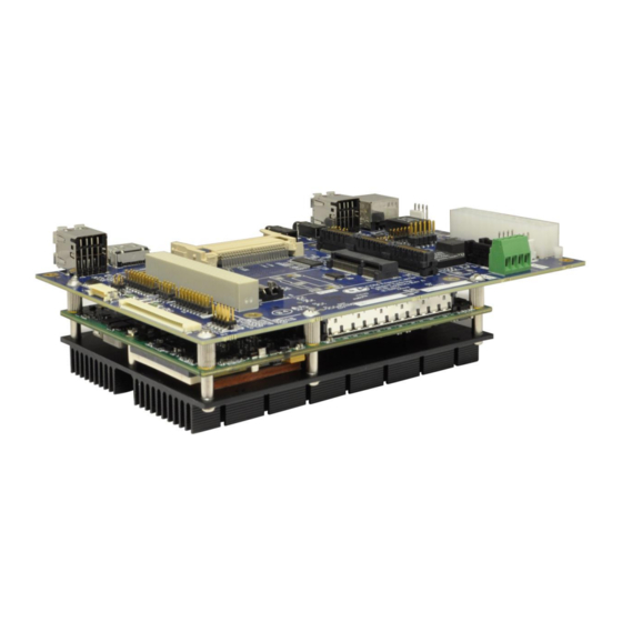
Connect Tech COM Express Type 2 Carrier Board - User Manual Mechanical Devkit standoffs A Devkit, part number DEV005 can be purchased to facilitate bench top development. The Devkit includes screws, standoffs and spacers. See picture below. Devkit (DEV005) parts list... -
Page 33: Devkit Installation Example
Connect Tech COM Express Type 2 Carrier Board - User Manual Devkit Installation Example Three corners of the PCB: Qty (6) 20mm Male/Female Hex Stand offs. Stack in pairs to achieve height as needed. Qty (3) 5mm M2.5 Screws Corner of PCB as seen in picture below: ... -
Page 34: Com Express Carrier Board Dimensions
COM Express Carrier Board Dimensions...
Need help?
Do you have a question about the COM Express 2 and is the answer not in the manual?
Questions and answers