Table of Contents
Advertisement
Quick Links
Advertisement
Table of Contents

Related Manuals for Connect Tech CCG010


Summary of Contents for Connect Tech CCG010
-
Page 1: Table Of Contents
® COM Express Type 10 Mini Carrier CCG010 / CCG020 Connect Tech Inc. Tel: 519-836-1291 42 Arrow Road Toll: 800-426-8979 (North America only) Guelph, Ontario Fax: 519-836-4878 N1K 1S6 Email: sales@connecttech.com www.connecttech.com support@connecttech.com CTIM-00120 Revision 0.12 2018-01-05... -
Page 2: Table Of Contents
Serial Line Modes ................................22 Examples ................................... 22 Audio ................................23 Software Support for the CS4207 ....................... 23 External SATA (CCG010 Only) ........................24 microSD Card Connector ..........................25 mini PCIe & mSATA Slots ........................... 26 Dual Function mini PCIe mSATA Slots ..................... 26 Half and Full Length mini PCIe / mSATA module Installation ............ - Page 3 Mechanical Drawings & Models ......................35 Cable Kits ............................37 CCG010 Cable Kit - CKG014 – “Full” Cable Kit ..................37 CCG010 Cable Kit - CKG015 – “Starter” Cable Kit ..................37 CCG020 Cable Kit - CKG035 – “Full” Cable Kit ..................38 CCG020 Cable Kit - CKG058 –...
-
Page 4: Preface
The information contained within this user’s guide, including but not limited to any product specification, is subject to change without notice. Connect Tech assumes no liability for any damages incurred directly or indirectly from any technical or typographical errors or omissions contained herein or for discrepancies between the product and the user’s guide. -
Page 5: Limited Product Warranty
Connect Tech Inc.'s opinion, fail to be in good working order during the warranty period, Connect Tech Inc. will, at its option, repair or replace this product at no charge, provided that the product has not been subjected to abuse, misuse, accident, disaster or non-Connect Tech Inc. authorized modification or repair. -
Page 6: Esd Warning
ESD Warning Electronic components and circuits are sensitive to ElectroStatic Discharge (ESD). When handling any circuit board assemblies including Connect Tech COM Express carrier assemblies, it is recommended that ESD safety precautions be observed. ESD safe best practices include, but are not limited to: ... -
Page 7: Introduction
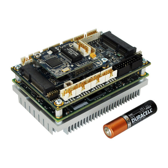
Introduction Connect Tech’s COM Express® Type 10 Mini Carrier Board is an extremely small carrier board featuring rugged, locking connectors and offers the ultimate durability. COM Express® Type 10 Mini Carrier Board is ideal for space constrained applications, harsh environments, demanding conditions and supports extended temperature ranges of -40°C to +85°C. -
Page 8: Product Features And Specifications
CCG010: 1 x mSATA, 1 x 1 Ext RA 7-pin Connector CCG020: 1 x mSATA CCG010: 8 x USB 2.0 Ports (6 to connectors, 2 to miniPCIe) CCG020: 2 x USB 3.0 Ports (Only if supported by COM Express Module) 6 x USB 2.0 Ports (2 to USB 3.0 connector, 2 to USB 2.0 connector, 2 to... -
Page 9: Product Overview
COM Express Type 10 Mini Carrier Manual Users Guide www.connecttech.com Product Overview Block Diagrams CCG010 Block Diagram CCG020 Block Diagram Document: CTIM-00120 Date: 2018-01-05 Page 9 of 44 Revision: 0.12 Connect Tech Inc. 800-426-8979 | 519-836-1291... -
Page 10: Connector Locations
COM Express Type 10 Mini Carrier Manual Users Guide www.connecttech.com Connector Locations CCG010 Top View CCG010 Bottom View Document: CTIM-00120 Date: 2018-01-05 Page 10 of 44 Revision: 0.12 Connect Tech Inc. 800-426-8979 | 519-836-1291... -
Page 11: Ccg020 Top View
COM Express Type 10 Mini Carrier Manual Users Guide www.connecttech.com CCG020 Top View CCG020 Bottom View Document: CTIM-00120 Date: 2018-01-05 Page 11 of 44 Revision: 0.12 Connect Tech Inc. 800-426-8979 | 519-836-1291... -
Page 12: Connector Summary
USB 2.0 Port 5 & 6 Connector Jumper Summary Designator Jumper Description 6-position 1.27mm Jumper Block RS-232/RS-485 Jumper Block 6-position 1.27mm Jumper Block Misc/System Jumper Block Document: CTIM-00120 Date: 2018-01-05 Page 12 of 44 Revision: 0.12 Connect Tech Inc. 800-426-8979 | 519-836-1291... -
Page 13: Detailed Feature Pinouts And Functional Descriptions
COM Express carrier via a Tyco fine pitch stacking connector. Function COM Express interface Location Carrier 3-6318491-6 Connector PN Manufacturer: TE Connectivity Mating 3-1827231-6 Connector PN Manufacturer: TE Connectivity Pinout See Appendix A Document: CTIM-00120 Date: 2018-01-05 Page 13 of 44 Revision: 0.12 Connect Tech Inc. 800-426-8979 | 519-836-1291... -
Page 14: Display Outputs
[2] – BKLT Control – This signal can be connected to the COM Express backlight control pin or to GND via Jumper J2 position D and E. Document: CTIM-00120 Date: 2018-01-05 Page 14 of 44 Revision: 0.12 Connect Tech Inc. 800-426-8979 | 519-836-1291... -
Page 15: Lvds Backlight Power Connector
LVDS backlight Inverter power Location Carrier SM02B-BHSS-1-TB - Manufacturer: JST Connector PN Mating BHSR-02VS-1 (N) - Manufacturer: JST Connector PN Pinout Signal VA LED VK LED Document: CTIM-00120 Date: 2018-01-05 Page 15 of 44 Revision: 0.12 Connect Tech Inc. 800-426-8979 | 519-836-1291... -
Page 16: Displayport ++ (Ddi) Video Connector
DP_AUX_SEL [1] Auxiliary Selection [1] – For DP_AUX_SEL – Cable assembly must tie high (+3.3V) for HDMI/DVI output and low (GND) for DisplayPort output. Document: CTIM-00120 Date: 2018-01-05 Page 16 of 44 Revision: 0.12 Connect Tech Inc. 800-426-8979 | 519-836-1291... -
Page 17: Hdmi / Dvi / Vga
Note: Some newer processor series like the Intel Baytrail can actually output proper TMDS signaling, so no external dongles are needed in this case. TMDS actually comes out directly from the module and carrier. Document: CTIM-00120 Date: 2018-01-05 Page 17 of 44 Revision: 0.12 Connect Tech Inc. 800-426-8979 | 519-836-1291... -
Page 18: Usb
Port B GND [1] – B-VBUS – This voltage can be disable for USB Client mode on USB port 6, just installing jumper J2 position B. Document: CTIM-00120 Date: 2018-01-05 Page 18 of 44 Revision: 0.12 Connect Tech Inc. 800-426-8979 | 519-836-1291... -
Page 19: Usb 3.0/2.0 Port Connectors
Port B - SSTX- Port B - SSTX+ Port A - D- Port A - D+ Port B - D- Port B - D+ Document: CTIM-00120 Date: 2018-01-05 Page 19 of 44 Revision: 0.12 Connect Tech Inc. 800-426-8979 | 519-836-1291... -
Page 20: 10/100/1000 Ethernet (Gbe) Connector
Additional drivers will be needed to properly operate the GBE Port 1 on the COM Express carrier. These drivers can be downloaded directly from Intel website from the below link: http://downloadcenter.intel.com/SearchResult.aspx?lang=eng&ProductFamily=Ethernet+Components&Produc tLine=Ethernet+Controllers&ProductProduct=Intel%C2%AE+82574+Gigabit+Ethernet+Controller Document: CTIM-00120 Date: 2018-01-05 Page 20 of 44 Revision: 0.12 Connect Tech Inc. 800-426-8979 | 519-836-1291... -
Page 21: Serial
RS-232 1 Transmit / RS-485 1 Transmit + 232RX1/485RX+ RS-232 1 Transmit / RS-485 1 Transmit + 485TX1- RS-485 1 Transmit - 485RX1+ RS-485 1 Receive - Document: CTIM-00120 Date: 2018-01-05 Page 21 of 44 Revision: 0.12 Connect Tech Inc. 800-426-8979 | 519-836-1291... -
Page 22: Rs-232/485 Jumper Configuration
Position A – M0 Position B – M1 Port 0 Selected Mode Port 1 Selected Mode RS-232 RS-232 RS-422/485 RS-422/485 RS-232 RS-422/485 Undefined Undefined Examples Document: CTIM-00120 Date: 2018-01-05 Page 22 of 44 Revision: 0.12 Connect Tech Inc. 800-426-8979 | 519-836-1291... -
Page 23: Audio
Additional drivers will be needed to properly operate audio on the COM Express carrier. Some downloadable links can be found below. Windows XP Driver: http://www.cirrus.com/en/pubs/software/CS4207_WinXP_1-0-0-38.zip Windows 7/Vista Driver: http://www.cirrus.com/en/pubs/software/CS4207_WinVista_Win7_32-64-bit_6- 6001-1-30.zip Linux Driver: Included in kernels 2.6.30 and up. Document: CTIM-00120 Date: 2018-01-05 Page 23 of 44 Revision: 0.12 Connect Tech Inc. 800-426-8979 | 519-836-1291... -
Page 24: External Sata (Ccg010 Only)
Industry standard vertical entry SATA host Connector PN connector with locking capability Mating Industry SATA cable with locking tab Connector PN Pinout Signal SATA_TX_P SATA_TX_N SATA_RX_N SATA_RX_P Document: CTIM-00120 Date: 2018-01-05 Page 24 of 44 Revision: 0.12 Connect Tech Inc. 800-426-8979 | 519-836-1291... -
Page 25: Microsd Card Connector
Connector PN Pinout SDIO Signal COM Express GPIO Mapping SD_D2 GPI2 SD_D3 GPI3 SD_CMD GPO1 SD_VCC (+3.3V) SD_CLK GPO0 SD_D0 GPI0 SD_D1 GPI1 SD_CD# GP03 Document: CTIM-00120 Date: 2018-01-05 Page 25 of 44 Revision: 0.12 Connect Tech Inc. 800-426-8979 | 519-836-1291... -
Page 26: Mini Pcie & Msata Slots
PCIe / SATA Dual Functionality Diagram (U12) ** Selection between mSATA and mini pcie is done via Jumper J2 position F. (ON = mini pcie, OFF = mSATA) Document: CTIM-00120 Date: 2018-01-05 Page 26 of 44 Revision: 0.12 Connect Tech Inc. 800-426-8979 | 519-836-1291... -
Page 27: Half And Full Length Mini Pcie / Msata Module Installation
Below is a diagram of how the standoffs and mounting hardware should be installed. If the screw mount type standoffs is not preferred a solder-in standoff is also available. Document: CTIM-00120 Date: 2018-01-05 Page 27 of 44 Revision: 0.12 Connect Tech Inc. 800-426-8979 | 519-836-1291... -
Page 28: Ccg020 - External Hard Drive Installation
Locations U12 (“right slot” mini pcie/mSATA) Carrier Standard 52-pin 0.8mm pitch PCI Express Connector PN mini Card connector Pinout mSATA Pinout mini pcie Pinout Document: CTIM-00120 Date: 2018-01-05 Page 28 of 44 Revision: 0.12 Connect Tech Inc. 800-426-8979 | 519-836-1291... - Page 29 PCIe TX+ From Host System SATA RX+ From Host System USB D- USB D+ +3.3V +3.3V +3.3V +3.3V RESV RESV +1.5V +1.5V +3.3V +3.3V Document: CTIM-00120 Date: 2018-01-05 Page 29 of 44 Revision: 0.12 Connect Tech Inc. 800-426-8979 | 519-836-1291...
-
Page 30: System Miscellaneous
Enable +5V Backlight Supply to P9 Connect LVDS PWM Signal to GND Connect LVDS PWM to COM Express mini PCIe (ON) / mSATA (OFF) selection Document: CTIM-00120 Date: 2018-01-05 Page 30 of 44 Revision: 0.12 Connect Tech Inc. 800-426-8979 | 519-836-1291... -
Page 31: Input Power & Control
RTC battery on the module so in this case this connector can be left disconnected. Connect Tech provides a Battery with cable assembly in any of the “Full” or “Starter” cable kits, please see the Cable Section of this manual for more details. If this battery is not sufficient for the application, a different battery cable can be designed. -
Page 32: Typical Hardware Installation Procedure
Connect the power cable to power supply Ensure your power supply is in the range of +6V to +14V DC Switch on the power supply On-board Indicator LEDs (CCG010 Only) The COM Express Type 10 Mini Carrier has 10 on-board indicator LEDs. Description... -
Page 33: Power Consumption And Thermals
Below are some thermal images of the carrier running standalone at room temperature with and without a module installed. TOP VIEW BOTTOM VIEW SIDE VIEW Document: CTIM-00120 Date: 2018-01-05 Page 33 of 44 Revision: 0.12 Connect Tech Inc. 800-426-8979 | 519-836-1291... - Page 34 COM Express Type 10 Mini Carrier Manual Users Guide www.connecttech.com Document: CTIM-00120 Date: 2018-01-05 Page 34 of 44 Revision: 0.12 Connect Tech Inc. 800-426-8979 | 519-836-1291...
-
Page 35: Mechanical Drawings & Models
Mechanical Drawings & Models A complete 3D STEP Model file of carrier board can be downloaded here: http://www.connecttech.com/ftp/3d_models/CCG010-20_3D_MODEL.zip 2D Mechanical Dimensioned Drawing (CCG010) – All dimensions are shown in (mm) Document: CTIM-00120 Date: 2018-01-05 Page 35 of 44 Revision: 0.12... - Page 36 COM Express Type 10 Mini Carrier Manual Users Guide www.connecttech.com 2D Mechanical Dimensioned Drawing (CCG020) – All dimensions are shown in (mm) Document: CTIM-00120 Date: 2018-01-05 Page 36 of 44 Revision: 0.12 Connect Tech Inc. 800-426-8979 | 519-836-1291...
-
Page 37: Cable Kits
Cable Kits The following tables summarize the COM Express carrier’s available cable kits from Connect Tech. These cable kits all include 200mm length breakout cables to PC type panel mountable connectors. These cables can be used for production deployment or for lab bring-up and test purposes. -
Page 38: Ccg020 Cable Kit - Ckg035 - "Full" Cable Kit
Dual USB 3.0 to 20-pin RA USB3.0 Cable Panel Mount: Right Angle Outer CBG287 Exit Dual USB 3.0 to 20-pin RA USB3.0 Cable Panel Mount: Vertical Exit CBG288 Document: CTIM-00120 Date: 2018-01-05 Page 38 of 44 Revision: 0.12 Connect Tech Inc. 800-426-8979 | 519-836-1291... -
Page 39: Appendix A - Com Express Signal/Pinout Connection Details
HD Audio (P13) Output HDA_RST# HD Audio (P13) Output GND (FIXED) Power HDA_BITCLK HD Audio (P13) Output HDA_SDOUT HD Audio (P13) Output BIOS_DISABLE# Input Document: CTIM-00120 Date: 2018-01-05 Page 39 of 44 Revision: 0.12 Connect Tech Inc. 800-426-8979 | 519-836-1291... - Page 40 LVDS Video (P9) Output LVDS_A1+ LVDS Video (P9) Output LVDS_A1- LVDS Video (P9) Output LVDS_A2+ LVDS Video (P9) Output LVDS_A2- LVDS Video (P9) Output Document: CTIM-00120 Date: 2018-01-05 Page 40 of 44 Revision: 0.12 Connect Tech Inc. 800-426-8979 | 519-836-1291...
- Page 41 Input Power +VIN (P4) Power GND (FIXED) A110 Power GND (FIXED) Power GBE0_ACT# GBE Port 0 (P1B) Output LPC_FRAME# Output LPC_AD0 LPC_AD1 LPC_AD2 LPC_AD3 LPC_DRQ0# Input Document: CTIM-00120 Date: 2018-01-05 Page 41 of 44 Revision: 0.12 Connect Tech Inc. 800-426-8979 | 519-836-1291...
- Page 42 USB 2.0 Port 1 (P14B) / (P6)* USB1+ USB 2.0 Port 1 (P14B) / (P6)* EXCD1_PERST# Output EXCD1_CPPE# Input SYS_RESET# System Header (P12) Input CB_RESET# Carrier Board Internal Circuitry Output Document: CTIM-00120 Date: 2018-01-05 Page 42 of 44 Revision: 0.12 Connect Tech Inc. 800-426-8979 | 519-836-1291...
- Page 43 Carrier Board Internal Circuitry Power VCC_5V_SBY Carrier Board Internal Circuitry Power BIOS_DIS1# Input DD0_HPD DisplayPort++ Channel 0 (P2) Output GND (FIXED) Power DDI0_PAIR5+ Output DDI0_PAIR5- Output Document: CTIM-00120 Date: 2018-01-05 Page 43 of 44 Revision: 0.12 Connect Tech Inc. 800-426-8979 | 519-836-1291...
- Page 44 Input Power +VIN (P4) Power VCC_12V B108 Input Power +VIN (P4) Power VCC_12V B109 Input Power +VIN (P4) Power GND (FIXED) B110 Power Hello from the author Document: CTIM-00120 Date: 2018-01-05 Page 44 of 44 Revision: 0.12 Connect Tech Inc. 800-426-8979 | 519-836-1291...
Need help?
Do you have a question about the CCG010 and is the answer not in the manual?
Questions and answers