
Related Manuals for DFI VP101-M8M


Summary of Contents for DFI VP101-M8M
- Page 1 VP101-M8M ARM-Based In-vehicle Fanless Touch Panel PC User’s Manual © June 13, 2024 DFI Inc.
-
Page 2: Fcc And Doc Statement On Class A
1. The changes or modifications not expressly approved by the party responsible for com- are the properties of the respective owners. pliance could void the user’s authority to operate the equipment. 2. Shielded interface cables must be used in order to comply with the emission limits. User's Manual | VP101-M8M... -
Page 3: Table Of Contents
COM1 Debug (J10) ......................24 USB2_3 (UBJ1) ......................24 Speaker (AUJ1) ......................25 Audio (AUJ2) ........................25 DIO (IOJ1) ........................26 I2C (J8) ...........................26 VP IO (VPJ1) ........................27 LVDS (J11) ........................28 Pin Assignment- COM Ports and CAN Bus ................29 CAN Bus .........................29 COM1 ..........................29 User's Manual | VP101-M8M... -
Page 4: About This Manual
The manual is subject to change and update without notice, and may be based on editions that do not resemble your actual products. Please visit our website or contact our sales representa- • 1 x VP101-M8M System Unit tives for the latest editions. •... -
Page 5: Static Electricity Precautions
Make sure the system is placed or mounted correctly and stably to prevent the chance of dropping or falling may cause damage. • The openings on the system shall not be blocked and shall be kept in distance from User's Manual | VP101-M8M... -
Page 6: Chapter 1 - Introduction
Chapter 1 INTRODUCTION Chapter 1 - Introduction X Overview Bottom View Back View Reset Switch Power Input CAN Bus USB3.1 Gen1 Re-download Switch User's Manual | VP101-M8M... -
Page 7: Dimensions
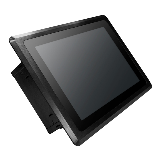
Smart Power Ignition Control Power delay and protection time setting DFI’s VP101-M8M equipped with ARM processor is the most energy-efficient All-in-One PC served as driver HMI with high brightness and high resolution TFT LCD display with capacitive touch. IP65 rated protection, wide operating temperature range, and anti-vibration ensure the system can withstand the bumpy, mountainous environment. -
Page 8: Specifications
OS SUPPORT Android Android 9.0 (default) Construction Aluminum + SGCC IP Rating IP65 Front Panel Protection MECHANISM Mounting Panel Mount /VESA Mount Dimensions (W x H x D) 294 x 193 x 53 mm Weight 1.67kg User's Manual | VP101-M8M... - Page 9 OP: Half-sine, 3G @ 11ms Shock Non-OP: Half-sine, 5G @ 11ms Standards and OP: Random, 1Grms @ 5~500Hz, 30min Vibration Certifications Non-OP: Sweep sine, 3Grms @ 10~500Hz, 30min Certifications CE, FCC, E-Mark R10, RoHS, UKCA (ongoing) User's Manual | VP101-M8M...
-
Page 10: Chapter 2 - Hardware Installations
2. Disconnect all power cords and cables. Step 1: The 8 screws of the system are used to secure the cover to the chassis. Remove the screws and put them in a safe place for later use. User's Manual | VP101-M8M... - Page 11 Chapter 2 HARDWARE INSTALLATION Step 2: Step 3: Slide the cover to open the system. The boards can be easily accessed after the chassis cover is removed. System Board Power Board User's Manual | VP101-M8M...
-
Page 12: Installing An M.2 Card
Screw tight the card onto the stand-off with a screw driver and a stand-off screw until the gap between the card and the stand-off closes up. The card should be lying parallel to the board when it’s correctly mounted. User's Manual | VP101-M8M... -
Page 13: Mounting Options
The clamps (Clamps) must be positioned and secured diagonally. Tighten the clamp’s screw using an electric screwdriver by pressing the white plastic cap onto the back of the panel. The illustration below shows that all clamps are properly mounted. screw User's Manual | VP101-M8M... -
Page 14: Chapter 3 - System Settings
ESD protection by wearing an antistatic wrist strap and attaching it to a metal part of the system chassis. If a wrist strap is unavailable, establish and maintain contact with the system chassis throughout any procedures requiring ESD protection. User's Manual | VP101-M8M... -
Page 15: System Board
Chapter 3 SYSTEM SETTINGS System Board System Board M.2 B key M.2 E key USB2_4 USB2_3 HDMI VP IO Battery COM1 Debug Power Link Boot CFG SIM Slot LVDS USB3.0 LED Backlight DC-IN Audio Speaker User's Manual | VP101-M8M... -
Page 16: System Board - Usd Card Slot
Chapter 3 SYSTEM SETTINGS System Board - uSD Card Slot System Board uSD Card Slot User's Manual | VP101-M8M... -
Page 17: Jumper Settings- Power Board
X Jumper Settings- Power Board Remote Switch High/Low Active (JP2) Host Bus Communication (JP3, JP4) „ 1-2 On: Reserved „ 2-3 On: TX/RX UART (default) „ 1-2 On: High Active (default) „ 2-3 On: Low Active User's Manual | VP101-M8M... -
Page 18: Sw1
Off, delay = 0 second by default Important: Power-off the system and then unplug the power cord prior to setting the switch- es. Failure to do so will cause severe damage to the system and components. User's Manual | VP101-M8M... -
Page 19: Power On Delay Time Select
POWER ON Delay Time Select Delay Duration 10 seconds (default) 30 seconds 1 miniute 5 minutes POWER OFF Delay Time Select Delay Duration 30 seconds (default) 1 minute 3 minutes 5 minutes 10 minutes 15 minutes 30 minutes 1 hour User's Manual | VP101-M8M... -
Page 20: Jumper Settings- System Board
„ 1-2 Off: Internal Boot (default) „ 5-6 Off: EMMC@eSDHC3 (default) „ 5-6 On: Backlight Power 12V (default) „ 1-2 On: Serial Downloader „ 5-6 On: uSD@eSDHC2 „ 1-3 On: 5V „ 4-6 On: Backlight Power 5V User's Manual | VP101-M8M... -
Page 21: Pin Assignment- Power Board
The 9V~36V In box headers are for ignition and power input to the power board, which then converts to 12VDC for output to the system board. 12VSB Jumper Settings 12VSB Power on/off, delay time, and other power related aspects can be configured via SW1 as previ- ously instructed in this chapter. User's Manual | VP101-M8M... -
Page 22: Mcu Connector (J2)
Chapter 3 SYSTEM SETTINGS MCU Debug (JP1) MCU Connector (J2) Assignment Assignment UART_TX UART_RX SYS_SWDIO SYS_SWCLK STMCU_RST# User's Manual | VP101-M8M... -
Page 23: Remote Switch (J3)
Chapter 3 SYSTEM SETTINGS Remote Switch (J3) Assignment Power Button User's Manual | VP101-M8M... -
Page 24: Pin Assignment- System Board
Chapter 3 SYSTEM SETTINGS X Pin Assignment- System Board USB2_3 (UBJ1) COM1 Debug (J10) M.2 B key M.2 B key M.2 E key M.2 E key Assignment Assignment +3.3V USBDN UART1_RX USBDP UART1_TX User's Manual | VP101-M8M... -
Page 25: Speaker (Auj1)
Chapter 3 SYSTEM SETTINGS Speaker (AUJ1) Audio (AUJ2) M.2 B key M.2 B key M.2 E key M.2 E key Assignment Assignment Assignment SPK_R- LOUT_L SPK_R+ SPK_L+ LOUT_R SPK_L- AGND MIC_IN User's Manual | VP101-M8M... -
Page 26: Dio (Ioj1)
Chapter 3 SYSTEM SETTINGS DIO (IOJ1) I2C (J8) M.2 B key M.2 B key M.2 E key M.2 E key Assignment Assignment Assignment Assignment DIO0 DIO1 +3.3V_TP DIO2 DIO3 TP_SCL TP_ALT# DIO4 DIO5 TP_SDA TP_RST# DIO6 DIO7 User's Manual | VP101-M8M... -
Page 27: Vp Io (Vpj1)
Chapter 3 SYSTEM SETTINGS VP IO (VPJ1) M.2 B key M.2 E key Function Function CAN_GND SOUTN3 CAN_H LVDS_A2+ CAN_L SINN3 UR1_TX_232 SINN4 UR1_RX_232 SOUTN4 RTSN2 DTRN4 CTSN2 RTSN4 SOUTN2 CTSN4 SINN2 User's Manual | VP101-M8M... -
Page 28: Lvds (J11)
LVDS (J11) Function Function LVDS_A2- LVDS_B3+ LVDS_A2+ LVDS_B3- LVDS_A3- LVDS_B2+ M.2 B key LVDS_A3+ LVDS_B2- M.2 E key LVDS_A0- LVDS_B1+ LVDS_A0+ LVDS_B1- LVDS_A1- LVDS_B0+ LVDS_A1+ LVDS_B0- LVDS_A_CLK- LVDS_B_CLK- LVDS_A_CLK+ LVDS_B_CLK+ +VDD_3.3V +VDD_5V +VDD_3.3V +VDD_5V +VDD_3.3V +VDD_5V User's Manual | VP101-M8M... -
Page 29: Pin Assignment- Com Ports And Can Bus
Function Function COM2 Function Function SINN2 (RX) SOUTN2 (TX) RTSN2 CTSN2 COM3 Function Function SINN3 (RX) SOUTN3 (TX) CAN Bus Function Function CAN_L COM4 CAN_GND Function Function DCDN4 SINN4 (RX) CAN_H SOUTN4 (TX) DTRN4 RTSN4 CTSN4 User's Manual | VP101-M8M...
Need help?
Do you have a question about the VP101-M8M and is the answer not in the manual?
Questions and answers