
Related Manuals for Eagle Eye SLB Series

Summary of Contents for Eagle Eye SLB Series
- Page 1 SLB-Series User Manual SLB-S ERIES SMART DC L ANKS User Manual V1.1 GlobalTestSupply www. .com Find Quality Products Online at: sales@GlobalTestSupply.com...
-
Page 2: Table Of Contents
SLB-Series User Manual Contents Introduction ..........................4 Safety Information ........................4 Product Overview ........................5 Features ............................ 5 Parts List ............................ 6 Front View ..........................7 Rear View ..........................8 Display and Keypad ........................9 Menu Abbreviations ........................9 Testing Preparation ........................ 10 Standard Cables ........................ - Page 3 SLB-Series User Manual Other Tests ..........................33 Assistant Discharge Test ......................33 External Test ........................... 34 Charge Monitor ........................34 SLB Disconnection Workflow ....................35 Data Management ........................35 System Management ......................36 Time and Date Setting ......................37 Parameter Management ......................37 Function Settings ........................
-
Page 4: Introduction
This manual provides guided information on how to use Eagle Eye’s Smart Load Banks (SLB) Series safely and effectively. It is universal to all Eagle Eye SLB-Series models. Please read the manual carefully to obtain maximum performance of the load bank and its accessories. It will cover setup, installation, operation, and troubleshooting of the load bank and its accompanying Data View Management Software. -
Page 5: Product Overview
With the optional external current clamp, the Eagle Eye SLB-Series can be used to assist DC loads and monitor the total voltage, cell voltages, and current from both load sources. The external current clamp also allows the load bank to be setup as a charge monitor. -
Page 6: Parts List
SLB-Series User Manual Parts List After receiving your Eagle Eye SLB-Series, please ensure that no damage occurred during shipping. SLB-Series Unit Grounding Line Wireless Communication Data COM Terminal Antenna For communication between For communication with COM COM Terminal, Load Bank,... -
Page 7: Front View
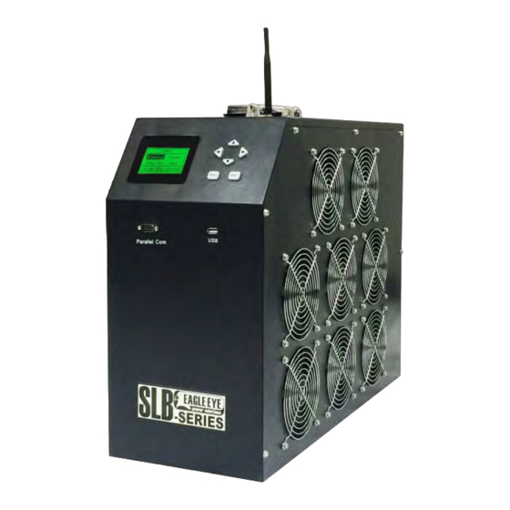
SLB-Series User Manual 3-Lead Voltage Cable AC Power Cord For 4, 6, 12V cells Front View The front of the SLB load bank houses all the controls for operating the unit. Use the directional buttons to navigate the menu. Continue on for details on using the keypad. SLB-Series (Medium Size) 1. -
Page 8: Rear View
SLB-Series User Manual Rear View All cables connect to the back side, for details on connecting cables continue reading. SLB-Series Rear View (Medium Size) 1. AC power input 2. Connection for external current clamp (optional) IMPORTANT: Some models will have 3. -
Page 9: Display And Keypad
SLB-Series User Manual 5. Connection for string voltage test leads 6. Connection for ground 7. Breaker switch* (required to be on for discharge testing) 8. Main unit power switch Display and Keypad All tests and functions are controlled from the display and keypad; the software is not used for control of the load bank. -
Page 10: Testing Preparation
SLB-Series User Manual Case/DAC syst acquisition case system charge time comm communication total exit voltage Testing Preparation This section details how to connect all of the test leads and cables properly. Before working with the equipment, be sure to check the following: 1. - Page 11 SLB-Series User Manual *IMPORTANT: Some models will have (2) of each load cable connection as well as multiple breaker switches. When there are multiple connections and breakers, all connections must be made and all breaker switched must be on. Before connecting the load cables, the best method of connection for your application should be evaluated.
-
Page 12: Slb Connection Workflow
SLB-Series User Manual SLB Connection Workflow WARNING: Connect load cables to the load bank before connection to batteries. If connected to batteries first and the ends of the cables touch, an arc flash will occur due to a returned 1. Connect load cables to the back of the load bank and then to the battery bank 2. -
Page 13: Dac Connection
DAC & CT packages should be purchased. DAC Connection The DAC (Data Acquisition Case) is an optional, but fundamental accessory for the Eagle Eye SLB-Series. DACs are used for wireless data logging of each cells voltage in virtual real time. This allows the load bank to capture each individual cells performance throughout the load test to help isolate failed and weak cells. -
Page 14: Dac Test Leads Explained
SLB-Series User Manual About the DACs: Each DAC is powered by 8VDC from the batteries it is connected to. It attains this from the first 9 connections (7-lead harness) or first connection (3-lead harness). For cable management magnetic bolts are built into the bottom of DAC for attachment to metal surfaces. Each DAC has (2) serial ports for connection with test lead cables. -
Page 15: Dac Connection To 2V/1.2V Cells
SLB-Series User Manual Custom DAC kits are available upon request, the most common being 1.2V or 4V applications. NOTE: For all DAC connections, the first DAC must be connected to the most negative post of the battery string regardless of whether or not the battery string is numbered from positive to negative or negative to positive. -
Page 16: Dac Workflow Connection To 6V/12V Cells
SLB-Series User Manual 48V System - 2V Cells - 24 Jars 125V System, 2V cells, 60 Units DAC Workflow Connection to 6V/12V Cells: • For 6V/12V cells, use 3-Lead DAC cables • Start with DAC cable #1 (red serial connector) •... -
Page 17: Multiple Dac Notice
SLB-Series User Manual 125V System 12V Cells 10 Jars DAC1 DAC2 DAC3 Multiple DAC Notice : If there are more than one DAC and the battery system ends with spare leads on the last DAC, then connection of the last DAC will need to overlap with the previously connected DAC. -
Page 18: Software
Installation Insert your Eagle Eye USB drive that came with your new SLB-Series load bank. On the drive you will find the installation program: Battery DataView Management System Right click and run install. The installer window will appear. Click Next & confirm installation. -
Page 19: Preparing For Testing
SLB-Series User Manual Preparing for Testing Open the DataView Software. Next, you will connect the Com Terminal to the PC using the provided RS-232-to-USB. Windows may auto install drivers for the device depending on your OS version and security settings. To verify if the drivers have successfully installed go to Start < Device Manager. In Device Manager, if the drivers are installed the Com Terminal will appear under Ports as a USB Serial Port with an assigned com number. - Page 20 SLB-Series User Manual You will receive a prompt box similar to this: Select Browse my computer for driver software. Go to the USB drive from Eagle Eye. Select the Com Terminal USB-R232 Drivers folder and press Ok. Windows will install the drivers.
- Page 21 SLB-Series User Manual In the DataView software, you will need to select “New String” or you can create your own string. As you see below we have created our own parent company, site, and named our battery string. To add a company, go to Edit < Add Customer. Once you have created the customer you can select the newly made customer and “Add Site”...
-
Page 22: Live Monitoring
SLB-Series User Manual The live monitor screen will now begin and you should start the test with the SLB-Series load bank. Notice: The load test cannot be started from the software. You must always start a discharge test on the load bank. Live Monitoring When the load bank begins testing the live monitor will show string voltage, discharge amperage, lowest 6 cells, and a chart with all cells on the home “String View”... - Page 23 SLB-Series User Manual Cell view allows you to choose individual or all cells Viewing tab Selected cells Adjustable chart graph Hover over any line for cell number and voltage GlobalTestSupply www. .com Find Quality Products Online at: sales@GlobalTestSupply.com...
- Page 24 SLB-Series User Manual Detailed View lists the discharge data in numerical values at approximately fifteen to half minute intervals. Values displayed; Time (date), Duration, String voltage, Discharge current, and each cell’s voltage. Selecting any data point will be reflected in the chart at the bottom of the screen. Hovering over any bar on the chart will display the corresponding cell number and its voltage value.
-
Page 25: Exporting Data
It is not necessary to live monitor a discharge to be able to view data. All discharge tests are stored on the SLB-Series load bank upon test completion. You should insert the Eagle Eye (or other) USB flash drive into the USB port of the SLB load bank. With the SLB go to Data > View Data >... - Page 26 SLB-Series User Manual Once imported, you will see the imported data on your list. Double click on the newly imported string and you will receive the test selection box; Select the test you wish to work with and then select either View – to view data, Export (to Microsoft Excel), or delete.
-
Page 27: Discharge Testing
SLB-Series User Manual Discharge Testing The following section covers steps for performing a discharge test. For an additional tutorial of the SLB-Series menu, please visit our tutorial video SLB Menu Walkthrough Battery String Discharge Using the keypad and LCD display, press the arrow keys up/down to highlight [Discharge] and press ENT to open the discharge test parameter screen. - Page 28 SLB-Series User Manual Cut-off Parameters for Discharge Auto-stop There are four user defined parameters for setting the discharge auto-stop. If any of these parameters are met the discharge test will end. Tot end U: 43 V Cell end U: 10.80V DIS C: 0000 Ah DIS Time: 10H 00M Parameters for Discharge Auto-Stop...
-
Page 29: Starting A Discharge Test
SLB-Series User Manual When to use positive setting: If the first battery in the string starts at the positive post, then DAC#1 will be connected to the last battery of the string and the setting will be set to positive. When the test starts DAC#1 will display the last battery of the string correctly as the last battery and not the first. -
Page 30: During The Discharge Test
SLB-Series User Manual During the Discharge Test During the discharge test the following parameters will be displayed: [Time]: Total and remaining time left on the test [DIS C]: String capacity discharged from batteries [U]: Indicates total voltage of string [I]: Indicates discharge current [Min cell]: Indicates cell # and voltage reading of lowest cell... - Page 31 SLB-Series User Manual Preparation 1. Ensure that all systems and cells are of the same voltage and amp hour capacity. 2. Be sure that DACs are grouped per string (buying additional DACs may be necessary) 3. Connect the load cables and string voltage leads to the main positive and negative posts of the strings in parallel 4.
-
Page 32: Continued Discharge
SLB-Series User Manual 1. Set the parameters for the first string, “String No.” indicates current string 2. Change “String No.” from “1” to “2” and so on to change parameters for each string 3. Press the down arrow to set parameters for the parallel strings 4. -
Page 33: Other Tests
SLB-Series User Manual Parallel Connection Performing a Parallel Load Test 1. Connect the two SLB-Series units using the serial cable, one unit will act as the main unit and the other as assistant unit 2. With both units select [System] under the main menu then select [Function]. Set both SLB units “Parallel”... -
Page 34: External Test
SLB-Series User Manual External Test External discharge test means that the load bank does not discharge batteries. Its main function is to display the values of current clamp and other loads (including battery string). Except battery total voltage and cell voltage (if connected with DAC), all the other values displayed on screen are from outside loads. -
Page 35: Slb Disconnection Workflow
SLB-Series User Manual Clamp type:025A/V Tot warn U: 57 V Cell warn U: 2.40 V 1# cell polar: - Monitor Parameters 4. Press ENT to begin monitoring the charge SLB Disconnection Workflow NOTE: When a discharge test has completed, it is recommended that the SLB-Series unit be left on to cool for 10 minutes. -
Page 36: System Management
SLB-Series User Manual Transferring Data to USB 1. Plug a USB flash drive into the front of the unit 2. Select a test date and chose [WritetoUSB] 3. Press ENT to transfer the test data to a USB flash drive 2012-06-25 012-07-25 View... -
Page 37: Time And Date Setting
SLB-Series User Manual Time and Date Setting Setting the system time and date correctly should be done before any discharge tests are performed. To set system time: 1. Select [Syst time] under the [System manage] menu 2. Use the up/down arrow keys to change number orientation 3. - Page 38 SLB-Series User Manual Zero calib Z0=5.0 Z1=0.0 Z2=400.0 Z3=400.0 calibrating... Zero Calibration After the zero calibration is complete the values should be as follows: Z0: Between 5 and 25 Z1: 0.0 Z2: Between 400 and 600 Z3: Between 400 and 600 Measurement Calibration This function is used to calibrate voltage and current values.
- Page 39 SLB-Series User Manual 4. Using a multi-meter, test the actual string voltage and enter this value under [Real U] 5. Press ENT to calibrate the string voltage To perform a Discharge Current Calibration: This option calibrates inner current and outside current. Inner current calibration is for the built- in current sensor, while outside current calibration is for optional external current clamp.
-
Page 40: Function Settings
Service & Maintenance Cleaning To clean Eagle Eye SLB-Series load banks simply wipe the units down with a damp cloth and mild soap. Do not use abrasives, solvents, or alcohol as they can deform and or discolor the unit. Occasionally, the load bank and its components should be blown off with air to remove dust buildup from the mosfets and control boards. -
Page 41: Troubleshooting
SLB-Series User Manual Calibration Eagle Eye recommends having the unit serviced periodically (2 years generally) to verify the unit firmware and components are calibrated and operating effectively. Troubleshooting See below for solutions to common troubleshooting scenarios: The LCD display on the front of the unit does not turn on 1. -
Page 42: Error Codes
SLB-Series User Manual Error Codes Category Title Error details and possible causes File operation File exist The USB has the file with the same name Open err Unable to open the file in the USB Not USB Unable to identify USB Create file err Create file unsuccessful to the USB Save file err... - Page 43 SLB-Series User Manual Voltage mismatch total voltage detected before discharge is beyond the scope of the currently selected voltage type Other I channel abnormal Current cannot be discharged. This is due to breakers being turned in the off position or damaged parts GlobalTestSupply www.
-
Page 44: Appendix A: General Specifications
SLB-Series User Manual APPENDIX A: General Specifications Technical Specifications Standard DAC: 1.2V , 2V, 6V, 12V / Optional: Custom DAC Cell Voltage: configurations available upon request Discharge Current Range: Single Load: 12 – 600A / Parallel Load: Up to 1200A Range: 10 –... -
Page 45: Appendix B: Discharge Specifications
SLB-Series User Manual APPENDIX B: Discharge Specifications Maximum Discharge Current At: Model 12VDC 24VDC 28VDC 36VDC 48VDC 80VDC 125VDC 240VDC 380VDC 480VDC SLB-12/24-400 SLB-24-300 SLB-24-400 SLB-24-500 SLB-24/36-100 77.7 SLB-24/36-300 233.3 SLB-24/36/48-300 233.3 SLB-24/36/48/80-200 SLB-24/48-200 SLB-24/48-300 SLB-24/48-300/600 SLB-24/48-600 SLB-28-100 SLB-28-150 SLB-28-300 SLB-28-500 SLB-48-150 SLB-48-300...
Need help?
Do you have a question about the SLB Series and is the answer not in the manual?
Questions and answers